
Pete Whitstone
True Classic
Here's how I created CC plates for the Scorpion. This information is provided for entertainment purposes only, and may not show all complete and relevant information, blah blah blah. If you attempt to duplicate this and you screw up and kill or injure yourself or someone else, it ain't my fault!
First, a quick lesson in caster and camber, and why you would want to adjust them.
Camber is the suspension setting that has the tires tilt in or out at the top. If the tires tilt in at the top (such as the rear tires on an X1/9 with worn springs), then it is said to have negative camber. If the tires tilt out at the top, like on old Model A’s, then they are said to have positive camber. So camber is a measurement, expressed in degrees, of how vertical the tire is. For cornering, some negative camber is desirable, because the outside tire in a turn (the passenger side tire in a left hand turn, for example) bears more weight, because the weight will transfer to that side of the car. Since there is more weight, the PS spring compresses while the DS spring expands. This is known as “body roll”. During the corner, if the tire has zero camber, it will tend to go to positive camber during the corner. However, if you “stack the deck” by putting negative camber in the wheel at static conditions, during the dynamic cornering condition it will (in theory) go to zero camber. That’s good in a corner because it increases the contact patch with the road, providing better cornering grip. At least, that’s my understanding of it, I’m sure many suspension gurus could point out all the flaws in that explanation.
Caster deals with how vertical the axle is, which is kind of an imaginary line, sometimes called the “effective kingpin inclination”. This is easier to visualize on a car with a double A-arm (double wishbone) suspension. When viewed from the side of the car, if the top ball joint is forward of the bottom, that is negative caster. If the bottom ball joint is forward of the top, that is positive caster. Some positive caster is desirable, because it provides an “on-center” feeling in the steering wheel. That is, if you are in a turn and you let go of the wheel, the steering wheel will straighten itself out. Sometimes this is referred to as “directional stability”. If you have negative caster, you get problems with wheel shimmy and other bad stuff. Remember turning the fork around 180 degrees on your bike when you were a kid and riding it that way? Kind of wobbly, wasn’t it?
Anyhow, with that rudimentary knowledge of the adjustability I was trying to create, we can get to the build.
After creating coilovers for my Scorpion, I had partial suspension adjustability, in that I could change spring ratios and ride height. But I also wanted to be able to adjust caster and camber. In a MacPherson strut suspension, this is typically done through caster/camber plates, but no one makes them for the Scorpion that I am aware of. There are some universal units out there that can be adapted, but they tend to be more expensive than the ones built for mass-produced cars. I figured if I was going to have to modify the universal unit anyway, I might as well save some money and start with something cheaper to be modified. When it comes to mass-produced cars people like to modify, the Fox-body Ford (78-93 Mustang) is king. And sure enough, they were the most economical unit available. I got a set off e-bay for about $110. Here is what they look like as delivered.
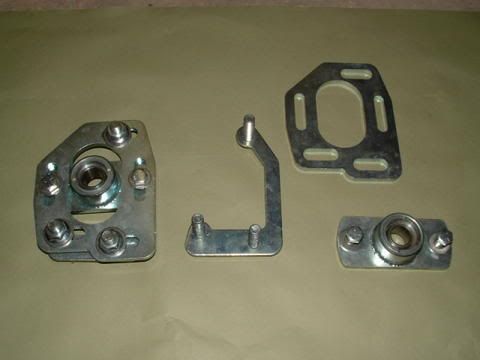
They also came with some short and long bushings to fit in the spherical bearing, but they were sized for the Fox-body strut rod and were of no use to this project.
Now I had to adapt them to my Scorpion. At first, I thought about cutting off the entire top of the strut tower and welding another plate in place. This plate would provide the mounting point for the CC plates. I actually had the cut-off wheel ready when I got cold feet. I decided I didn’t want to hack up my car that much, so I started looking at how I could do this less invasively.
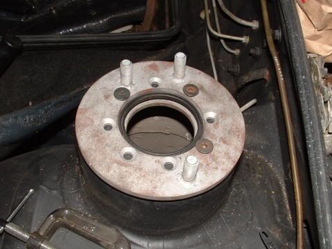
After thinking about it a while, I realized that I could still provide a sturdy mounting point for the CC plates by sandwiching the existing strut tower top between two plates of metal. After looking around the shop, I decided to modify a Fiat wheel spacer to provide the lower plate. The top piece would be heavier, turned out of .250 plate. It would provide the mounting point for the three main “lugs” of the CC plates. In order to attach it to the lower plate, I would use the stock strut top mounting holes, which are spaced at 0, 90 and 180 degrees. I also drilled five more holes for a total of eight, spaced every 45 degrees. Here is a shot of a top plate in progress, and a stock wheel spacer that has been turned down slightly to fit up into the strut tower.

Then I transferred the pattern of the three holes at 0, 90 and 180 degrees from the top plate to the bottom and drilled them.
The top plate had its eight holes countersunk with a chamfer bit, so the mounting screws would sit flush. I also liberated the three main mounting lugs from the stock CC plates, and cut off the heads. The remaining stud I welded into the top plate from the back, after countersinking those holes for increased weld penetration. Since the top plate must sit flat against the strut tower, there couldn’t be any bolt heads protruding out the back side.
Then I bolted the two plates in place, using the three holes that had been drilled. Here is a shot of what that looked like.
I used this mockup as a template to drill the other 5 holes, both through the strut tower and the lower plate.
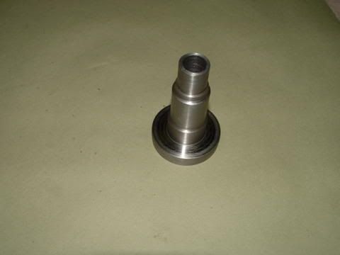
At this point I had a way to mount the CC plate to the car, but still needed to get the strut rod to interface with the spherical bearing in the CC plate. As I said earlier, the pieces that came with the CC plates were sized for the Fox-body strut. The entire weight of that corner of the car is transmitted through this piece, so it would have to be fairly beefy, and ideally would spread the load out over the top spring perch. This called for something large at the bottom and small enough at the top to fit tightly into the spherical bearing. Also, the strut rod must pass through it, so the inside diameter of the part must closely match the outside diameter of the VW strut rods that my coilover setup uses. I took some measurements and went to work on some 2-inch solid round stock. Here is the part that came out of that operation.
And here is a mock-up of how that part creates an interface between the top spring perch and the CC plate spherical bearing.
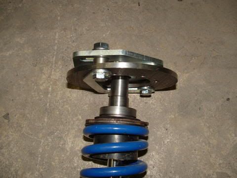
In my earlier write-up on the coilovers, I made mention of the fact that the 8.5 inch springs were not under compression when the unit was not installed in the car, which meant that, in theory at least, something could pop out of place if a wheel lifted. I don’t find this scenario tremendously likely, but in any event, this piece took up enough room to hold the spring under tension when not installed. This eliminated that concern.
So now I had to protect all that raw steel, so I powdercoated the parts matte black. Here is a shot of them ready to go in the oven.
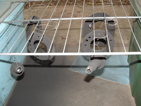
And after they have come out and cooled.
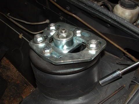
Now all that remained was assembly and adjustment. First I mounted the upper and lower plates to the car.
Notice the spacers that are sitting on the main mounting lugs. They came with the CC plates and are used to hold the sliding part of the plate slightly higher that the surface it’s sitting on, for freedom of movement. The eight countersunk mounting bolts do sit just slightly proud of the plate, and you can see where I notched one of them with an end mill because of its proximity to the mounting lug on the left. I could have clocked the three mounting lugs slightly different to avoid this, but that would shift the movement of the CC plates to an angle that was not “square” with the car. This would have reduced the effective adjustments somewhat, and made the caster adjustment slightly affect camber and vice versa, so I chose to go this route instead. Alternatively, I could have countersunk that bolt a little deeper, but didn’t want the strength compromise.
Next I assembled the CC plate onto the mounting point I had built. Here is what that looked like.
Finally, the coilover package was put in place, and I was ready to start adjusting.
You can see that I have both the caster and camber mostly maxed out. The camber readings on the front wheels are right at –2.0 degrees at this point. The plates provide for about 1.5 degrees of adjustability in this setup, so I can adjust from –0.5 to –2.0. Note that –0.5 is still more than the stock setting, but I don’t put enough miles on the car to worry too much about tire wear. Besides, the car is not a commuter, it’s a corner-carver and that’s how it’s used.
In case you were wondering, yes it does fit under the hood. Barely. There are probably easier ways to get from stock to adjustable, but this is how I chose to do it, and so far I’m pleased with the results.
First, a quick lesson in caster and camber, and why you would want to adjust them.
Camber is the suspension setting that has the tires tilt in or out at the top. If the tires tilt in at the top (such as the rear tires on an X1/9 with worn springs), then it is said to have negative camber. If the tires tilt out at the top, like on old Model A’s, then they are said to have positive camber. So camber is a measurement, expressed in degrees, of how vertical the tire is. For cornering, some negative camber is desirable, because the outside tire in a turn (the passenger side tire in a left hand turn, for example) bears more weight, because the weight will transfer to that side of the car. Since there is more weight, the PS spring compresses while the DS spring expands. This is known as “body roll”. During the corner, if the tire has zero camber, it will tend to go to positive camber during the corner. However, if you “stack the deck” by putting negative camber in the wheel at static conditions, during the dynamic cornering condition it will (in theory) go to zero camber. That’s good in a corner because it increases the contact patch with the road, providing better cornering grip. At least, that’s my understanding of it, I’m sure many suspension gurus could point out all the flaws in that explanation.
Caster deals with how vertical the axle is, which is kind of an imaginary line, sometimes called the “effective kingpin inclination”. This is easier to visualize on a car with a double A-arm (double wishbone) suspension. When viewed from the side of the car, if the top ball joint is forward of the bottom, that is negative caster. If the bottom ball joint is forward of the top, that is positive caster. Some positive caster is desirable, because it provides an “on-center” feeling in the steering wheel. That is, if you are in a turn and you let go of the wheel, the steering wheel will straighten itself out. Sometimes this is referred to as “directional stability”. If you have negative caster, you get problems with wheel shimmy and other bad stuff. Remember turning the fork around 180 degrees on your bike when you were a kid and riding it that way? Kind of wobbly, wasn’t it?
Anyhow, with that rudimentary knowledge of the adjustability I was trying to create, we can get to the build.
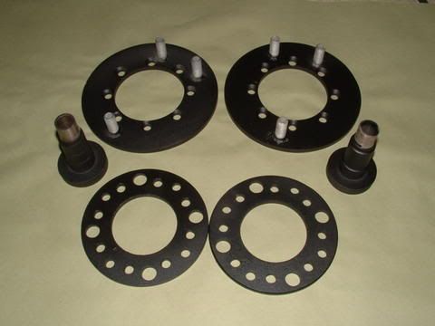
After creating coilovers for my Scorpion, I had partial suspension adjustability, in that I could change spring ratios and ride height. But I also wanted to be able to adjust caster and camber. In a MacPherson strut suspension, this is typically done through caster/camber plates, but no one makes them for the Scorpion that I am aware of. There are some universal units out there that can be adapted, but they tend to be more expensive than the ones built for mass-produced cars. I figured if I was going to have to modify the universal unit anyway, I might as well save some money and start with something cheaper to be modified. When it comes to mass-produced cars people like to modify, the Fox-body Ford (78-93 Mustang) is king. And sure enough, they were the most economical unit available. I got a set off e-bay for about $110. Here is what they look like as delivered.
They also came with some short and long bushings to fit in the spherical bearing, but they were sized for the Fox-body strut rod and were of no use to this project.
Now I had to adapt them to my Scorpion. At first, I thought about cutting off the entire top of the strut tower and welding another plate in place. This plate would provide the mounting point for the CC plates. I actually had the cut-off wheel ready when I got cold feet. I decided I didn’t want to hack up my car that much, so I started looking at how I could do this less invasively.
After thinking about it a while, I realized that I could still provide a sturdy mounting point for the CC plates by sandwiching the existing strut tower top between two plates of metal. After looking around the shop, I decided to modify a Fiat wheel spacer to provide the lower plate. The top piece would be heavier, turned out of .250 plate. It would provide the mounting point for the three main “lugs” of the CC plates. In order to attach it to the lower plate, I would use the stock strut top mounting holes, which are spaced at 0, 90 and 180 degrees. I also drilled five more holes for a total of eight, spaced every 45 degrees. Here is a shot of a top plate in progress, and a stock wheel spacer that has been turned down slightly to fit up into the strut tower.
Then I transferred the pattern of the three holes at 0, 90 and 180 degrees from the top plate to the bottom and drilled them.
The top plate had its eight holes countersunk with a chamfer bit, so the mounting screws would sit flush. I also liberated the three main mounting lugs from the stock CC plates, and cut off the heads. The remaining stud I welded into the top plate from the back, after countersinking those holes for increased weld penetration. Since the top plate must sit flat against the strut tower, there couldn’t be any bolt heads protruding out the back side.
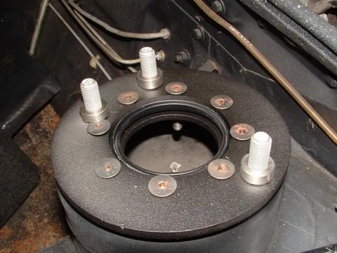
Then I bolted the two plates in place, using the three holes that had been drilled. Here is a shot of what that looked like.
I used this mockup as a template to drill the other 5 holes, both through the strut tower and the lower plate.
At this point I had a way to mount the CC plate to the car, but still needed to get the strut rod to interface with the spherical bearing in the CC plate. As I said earlier, the pieces that came with the CC plates were sized for the Fox-body strut. The entire weight of that corner of the car is transmitted through this piece, so it would have to be fairly beefy, and ideally would spread the load out over the top spring perch. This called for something large at the bottom and small enough at the top to fit tightly into the spherical bearing. Also, the strut rod must pass through it, so the inside diameter of the part must closely match the outside diameter of the VW strut rods that my coilover setup uses. I took some measurements and went to work on some 2-inch solid round stock. Here is the part that came out of that operation.
And here is a mock-up of how that part creates an interface between the top spring perch and the CC plate spherical bearing.
In my earlier write-up on the coilovers, I made mention of the fact that the 8.5 inch springs were not under compression when the unit was not installed in the car, which meant that, in theory at least, something could pop out of place if a wheel lifted. I don’t find this scenario tremendously likely, but in any event, this piece took up enough room to hold the spring under tension when not installed. This eliminated that concern.
So now I had to protect all that raw steel, so I powdercoated the parts matte black. Here is a shot of them ready to go in the oven.
And after they have come out and cooled.
Now all that remained was assembly and adjustment. First I mounted the upper and lower plates to the car.
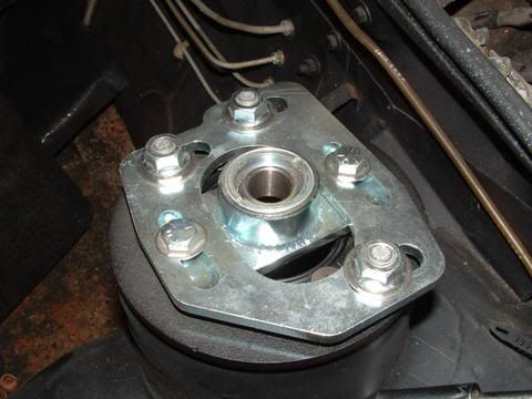
Notice the spacers that are sitting on the main mounting lugs. They came with the CC plates and are used to hold the sliding part of the plate slightly higher that the surface it’s sitting on, for freedom of movement. The eight countersunk mounting bolts do sit just slightly proud of the plate, and you can see where I notched one of them with an end mill because of its proximity to the mounting lug on the left. I could have clocked the three mounting lugs slightly different to avoid this, but that would shift the movement of the CC plates to an angle that was not “square” with the car. This would have reduced the effective adjustments somewhat, and made the caster adjustment slightly affect camber and vice versa, so I chose to go this route instead. Alternatively, I could have countersunk that bolt a little deeper, but didn’t want the strength compromise.
Next I assembled the CC plate onto the mounting point I had built. Here is what that looked like.
Finally, the coilover package was put in place, and I was ready to start adjusting.
You can see that I have both the caster and camber mostly maxed out. The camber readings on the front wheels are right at –2.0 degrees at this point. The plates provide for about 1.5 degrees of adjustability in this setup, so I can adjust from –0.5 to –2.0. Note that –0.5 is still more than the stock setting, but I don’t put enough miles on the car to worry too much about tire wear. Besides, the car is not a commuter, it’s a corner-carver and that’s how it’s used.
In case you were wondering, yes it does fit under the hood. Barely. There are probably easier ways to get from stock to adjustable, but this is how I chose to do it, and so far I’m pleased with the results.