Distributor
Ducellier Specifications
This is the distributor used on the early 1300 cars.
Static advance without vacuum is 10 degrees.
Bosch Specifications
From section 55-1 of the factory manual:
Type: Bosch - 0-237 Static Advance Carb - 5 degrees Static Advance FI - 10 degrees
Centrifugal Advance Carb - 23-27 degrees @ 5500 RPM Centrifugal Advance FI - 16-20 degrees @ 3500 RPM
Vacuum Advance Carb + air pump - 16-18 degrees @ 12 in.HG Vacuum Advance Carb w/o air pump - 26-30 degrees @ 12 in.HG Vacuum Advance FI - 12-16 degrees @ 11in.Hg
Total Advance (static + centrifugal) Carb - 28-32 Degrees @ 5500 RPM Total Advance (static + centrifugal) FI - 26-30 degrees @ 3500 RPM
FI Distributor # (Thanks Greg!) 0 237 002 050
Good find, Gregory. As a compilation:
0 237 002 020 is a carbureted model with full advance completed at 5500 RPM
0 237 002 050 is for the injected cars with full advance completed at 3500 RPM
I have taken them (both) apart before and compared. Advance weights are the same, springs seem to be the same, vacuum advance mechanism is the same (that is the mechanism inside the distrib, different vac advance is given by different capsules external) and the difference between the two is the slotted plate underneath that provides the stops for the advance. The carbureted model has longer slots for more advance.
If anyone has disassembled distributors laying around, I think that I may have the numbers from the slotted plate inside.
Disassembly / Testing
So, where do I start? This post was instigated by Tony Natoli and I thought it'd be a good challenge. As much as I know about electronic ignitions, the actual DETAILS of the X1/9 ignition has been swept aside (by me) purely from a lack of personal importance. (or trouble!) With that, let me share a few facts that I've gathered this afternoon regarding the inner workings of LATE MODEL distributors.
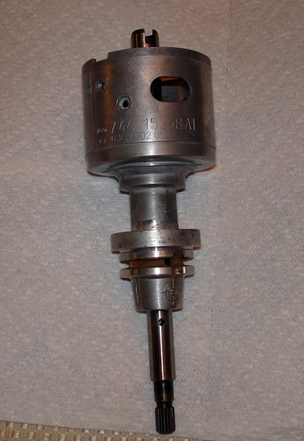
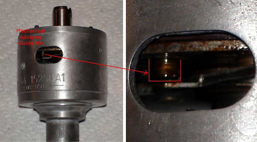
Let's start with a bare distributor, model numbers exposed. This photo was taken after I pulled the bottom pin, allowing removal of the shaft assembly through the top. The Mechanical advance also has to be removed, (as shown) but we'll get to that shortly.
There are 2 "E" clips that holds the flying trigger in place, one on top and one beneath. First remove the top clip and SLOWLY, carefully work the trigger unit up until it is free. You'll note a very small pin (photo to follow) that you DON'T want to lose.
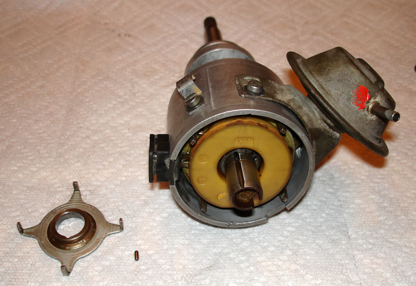
Here is the flying trigger removed, and the pin that locks it into place... Also note the second "E" cip that must also be removed.
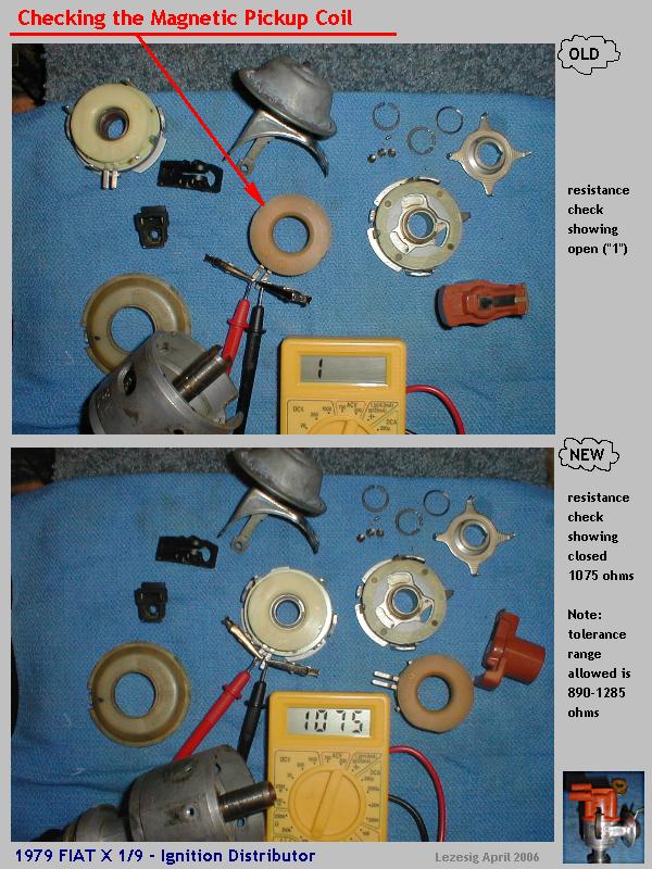
Once the second "E" clip is removed, remove the Vacuum advance assembly (2 screws) and the electrical connector to the distributor. (1 screw) NOTE: The plastic housing to this connector slides STRAIGHT OUT. (See image on right) Remove 1 screw (on the side) to release the pickup coil and slide the unit out completely.
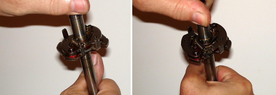
The mechanical advance should also be removed, relubricated and checked for free operation.
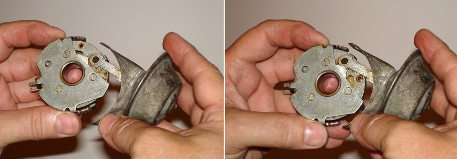
The pickup coil assembly has a magnet ring with 4 posts attached that rotates about 20 degrees or so. The vacuum advance attaches to a post (see pic below) that changes the location of the pickup. It is very important this assembly is allowed to rotate freely for this to function properly. Sluggish movement means a sluggish advance. In this particular modal, the vacuum advance unit was full of oil (don't ask me how!) and the magnet assembly was 'sticky'. The arm that extends from the bellows can be aggitated gently while the unit is held upside-down to check for foreign materials. (like gas or oil)
Note the positions of the vacuum advance. Re-attaching this sucker is a BEAR once you get everything assembled. The arm will only attach as shown in the position on the left.
And this is what you'll be "fishing" for...
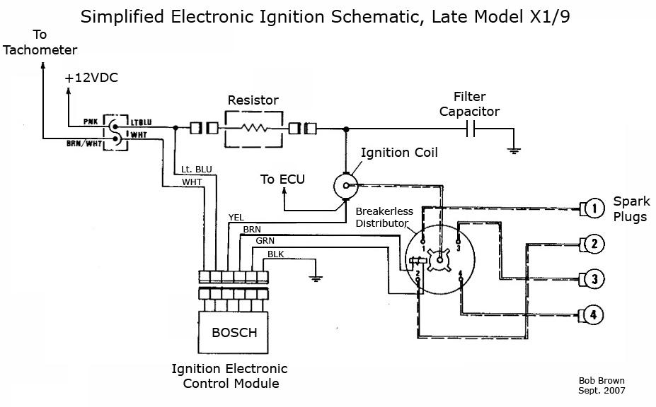
Make sure everything is lubricated when you re-assemble and you should be well on your way to an easy spark. (or zap, HA!) For reference, I'm including this schematic diagram (part from a Manual and part my additions) that ANYONE can use to make up your own electronic ignition for your X.
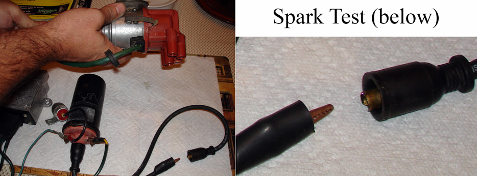
So to test my theory, I hooked this up to a power supply and tried it out. If you look carefully to the right, you'll see a spark. It was tuff getting a photo with the camera I was using. But the spark was really healthy. The spark is coming right out of the coil (not through the top of the distributor) as I rotate the distributor to generate spark.
Hope this comes in handy for your projects and hope you enjoyed! Bob Brown
