Rebuild your Bosch ICM for about 10 bucks.
Here’s a new twist on a subject that’s been broached a few different ways in past discussions of replacing the Bosch Ignition Control Module. I say “about 10 bucks” but the total might be as high as $15 if you have to go out and buy the misc. items.
I’ve seen photos where some have set up similar devices to replace their ailing Bosch ICM, but what I’m presenting here is a method you can use to actually rebuild your Bosch unit to something that’s actually superior to your existing unit. Plus, you won’t have to modify your wiring harness arrangement in your X1/9.
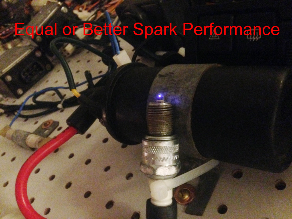
How superior you ask? For starters, the rebuild will hold spark in excess of 8K RPM, use less than half the current when the engine’s not running (saving your coil and resistor) and produce a spark equal to or better than the original Bosch ICM.
The module that will replace your “old tech PCB” is also by-far much more efficient than the original Bosch unit.
In the likely event the photos disappear from this posting, you can D/L the entire instruction HERE.
Here’s the detail on how to make it all happen…
What you'll need to modify the Bosch: (most of these items should be kicking around your shop)
1. An X1/9 Bosch Ignition Control Module, dead or alive!
2. A Dremel tool with an abrasive cutting wheel and a drill size that will accommodate a 8/32 tap or 5 or 6mm tap
3. A hand drill, or drill press. (recommended)
4. A screw driver, small hammer and a method of pry such as an old wood chisel
5. A tap (8/32 or 5mm or 6mm, your choice)
6. 4 screws for above thread size with a length of 12mm or 0.5 inch
7. 2 tapered oval head screws of the above size with a length 15mm or 0.625”
8. 2 nuts to accommodate the 2 tapered oval head screws
9. 3 stainless star washers to accommodate the above screws
10. Six 16Ga colored wires, 6” long (about 150mm) Preferred colors: 1 red, 1 brown, 1 green, 1 black, and 2 yellow.
11. A four inch 16Ga green wire with a red ring tongue connector attached at each end.
12. A Ring tongue (red color) crimp connector
13. A soldering station, good quality solder, wire cutters, strippers, crimp tool
14. Approx. 6” (about 150mm) of small Heat shrink tubing that will go over the above wire
15. A small amount of “Heat Sink Compound” or thermal conductive grease, found at computer stores or Radio Shack
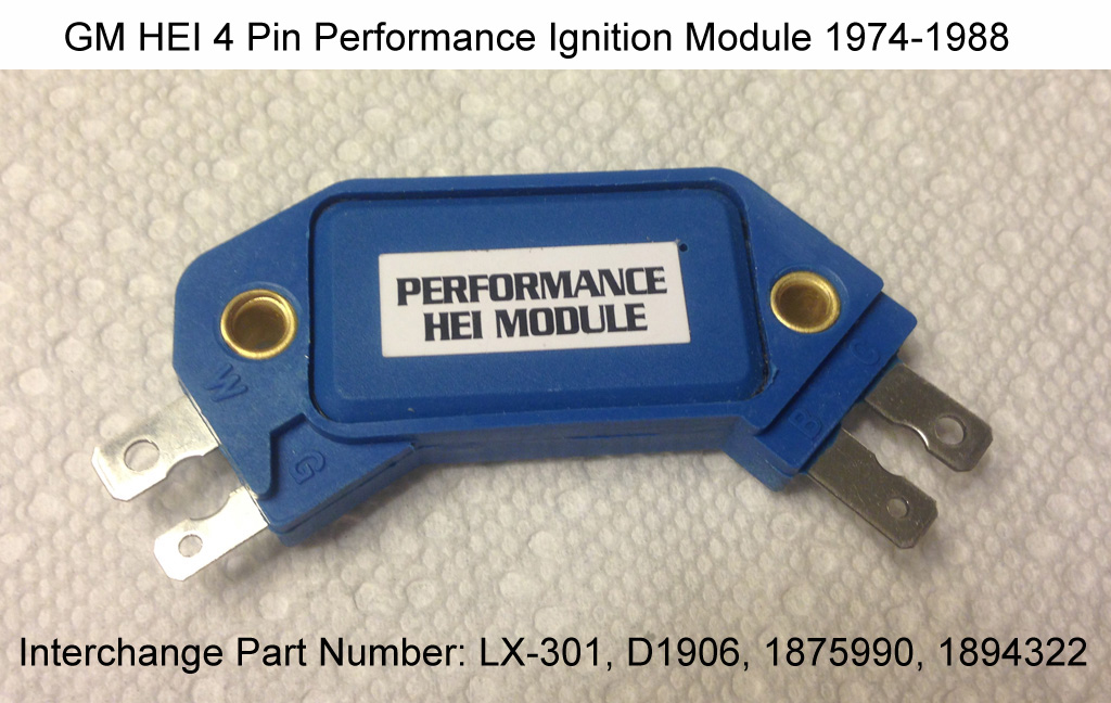
16. Last but not least, the main component: A GM HEI 4 Pin Performance Ignition Module. (LX-301 or D1906)
Let’s get started…
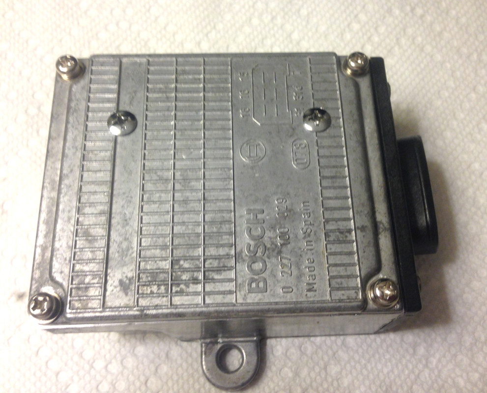
Looking at the top of your Bosch ICM, you’ll notice four “peened” (domed) aluminum fasteners holding the top cover securely to the module. This module wasn’t meant to be serviced, so removing these aluminum domes requires the use of a Dremel with an abrasive cutting wheel and a little patience. Carefully grinding off the domes (only) will allow you to pry off the cover and expose the inner workings. In my example, I had corrosion under one of the fasteners and it basically froze the stud to the cover. So removing it caused this leg to break off. (See missing stud in lower left corner of photo below)
After the cover has been removed, you will notice 3 screws holding the control board down plus some specific solder points (as noted) that must be separated from their connection points. It will be easiest to remove the screws last.
Using a soldering pencil, carefully separate the six connections from the connector housing from the PCB.
Next, unsolder the three points that connect the board from the power transistor, and cut (or unsolder) the 2 resistor points shown at the bottom of the illustration.
After removing the 3 screws, the board can be extracted. Save one of the 3 screws for later use!

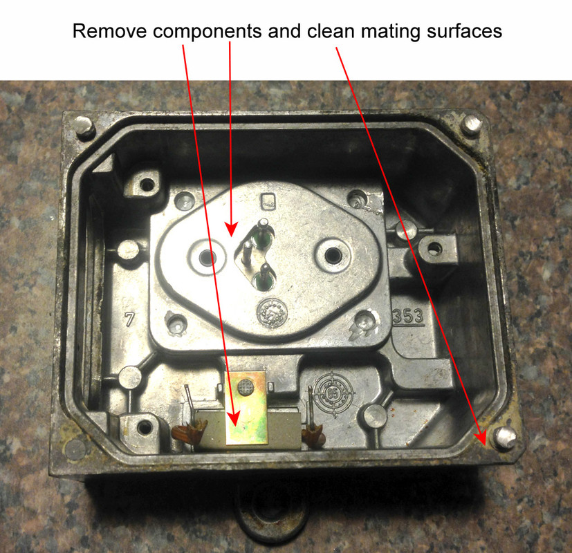
With the PCB removed, we can remove the remaining components inside the box and free up some space.
Using your Dremel tool with the abrasive cutting wheel, carefully grind flat the following areas:
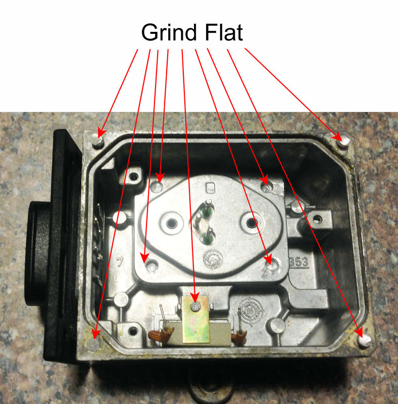
Once those areas are ground flat, you can remove the objects inside and clean up the surface area around the top lip that mates with the top cover.
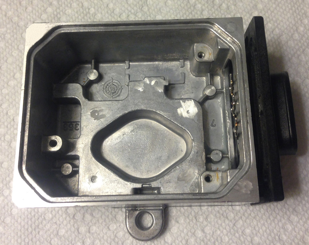
Below is a photo of an empty box with the mating surfaces cleaned and all components removed:
Next, you’ll need to re-fit the top cover to the box. I am not showing a photo of this, but be sure the top cover mating surface AND the rubber seals are clean.
Place the top cover onto the box. Using the holes located in the 4 corners as a guide, drill and tap new holes so that you can secure the top cover back on. It’s important that you drill the holes straight. In this circumstance, a drill press will be your best friend! Set the depth to about 0.5 inch (or about 13mm)
Installing the new module: (shown below)
This project will use the GM HEI Performance Ignition Module available at auto stores or eBay.
Other part numbers you can use are: LX-301, D1906, GM 1875990 or GM 1894322.
This is a “higher performance than stock” unit.
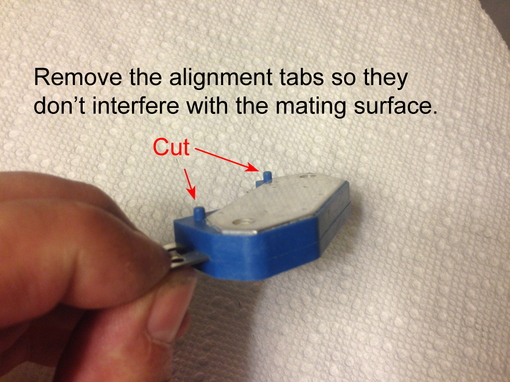
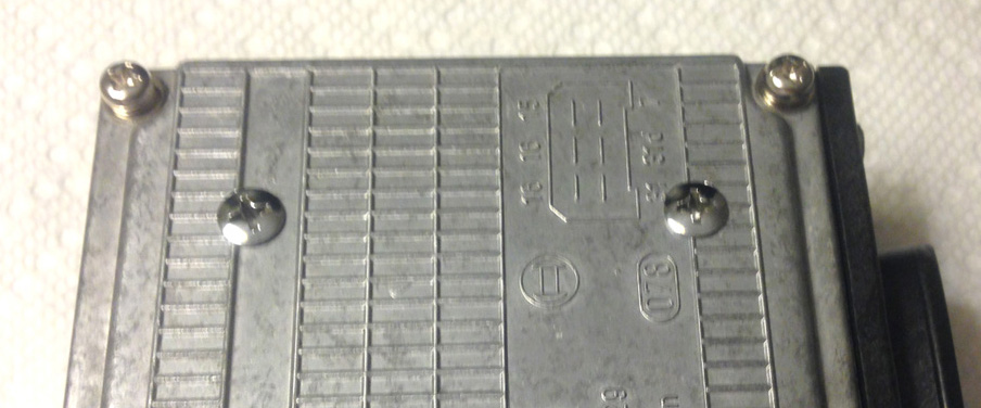
Prepping the new HEI module:
This unit has locating Tabs that must be removed. Failure to remove these tabs will cause the module to fail from overheating.
These modules are usually mounted to a chassis part or heat sink to allow them to run cool. For this project, we’ll mount it to inside the aluminum cover of the Bosch unit.
You’ll also note there are tabs that extend beyond the inside lip of the cover.
These tabs will be marked and cut as illustrated below. DO NOT BEND the terminals!!
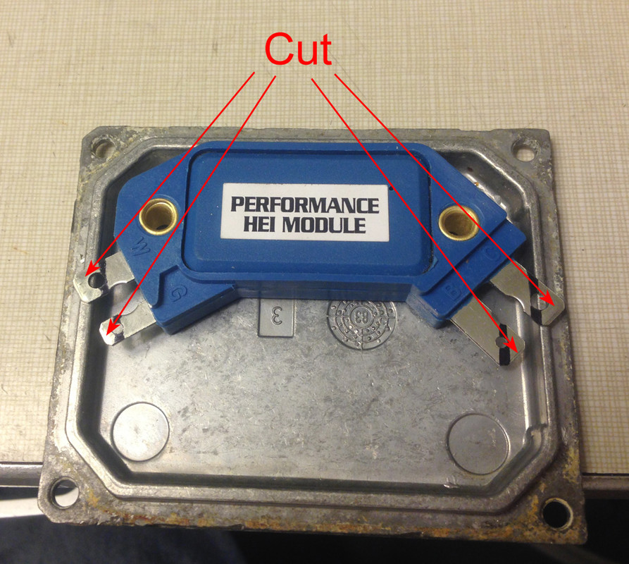
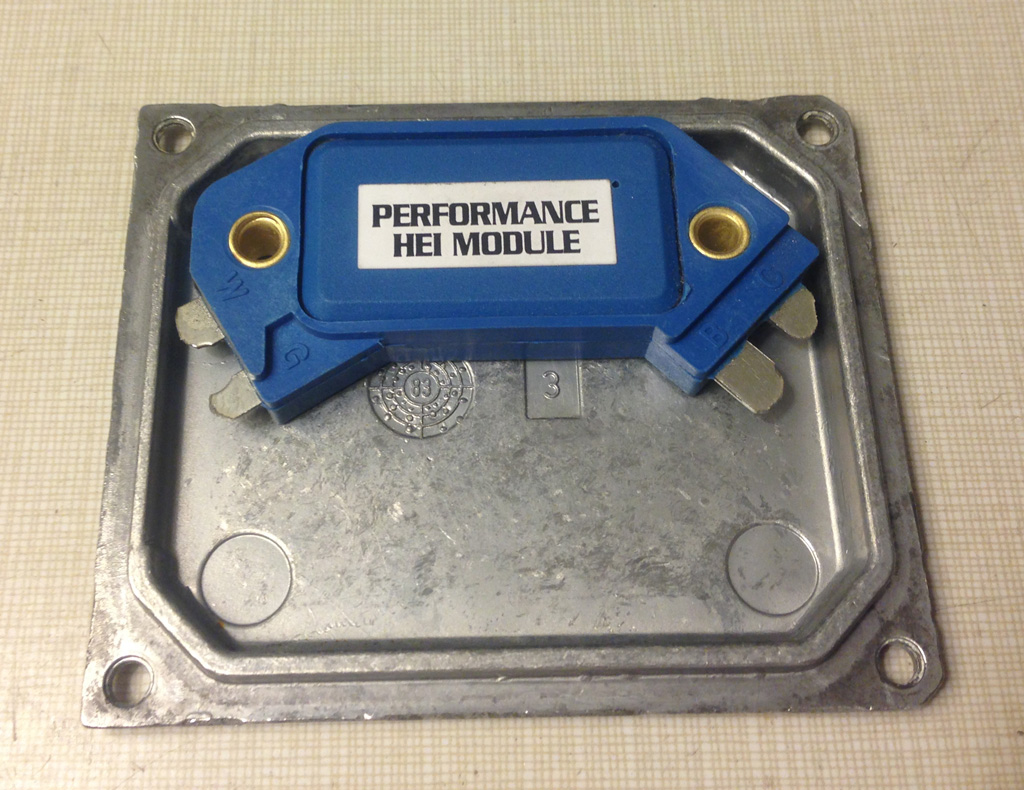
Note there should be plenty of clearance to the connections after cutting as shown below.
Next, we will mount the module to the cover as shown in the illustration below using the module as a guide.
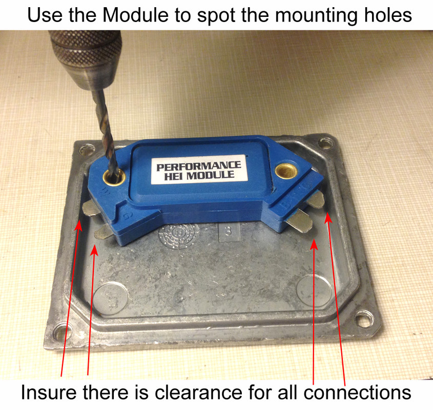
I recommend that you counter-sink the holes on the top (face) side so that the screws do not protrude far from the top surface.
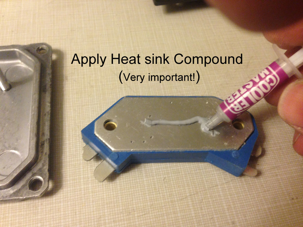
Once the holes are drilled and before mounting the HEI module, coat the back side surface of the module with Thermal conductive grease. Note that this is an important step in assuring good thermal conductivity to the Bosch unit. Omitting this step will cause premature failure of the module.
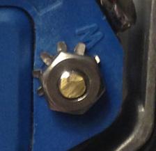
Very important: When securing the hardware to the HEI module, it’s vital that you use a star washer under each screw.
Insert one end of the 4 inch green wire (that has the ring tong terminal attached) under the post that’s located the furthest away from the large black Bosch connector.
After the module is secured to the cover, I cut the screw threads flush to avoid any sharp points.
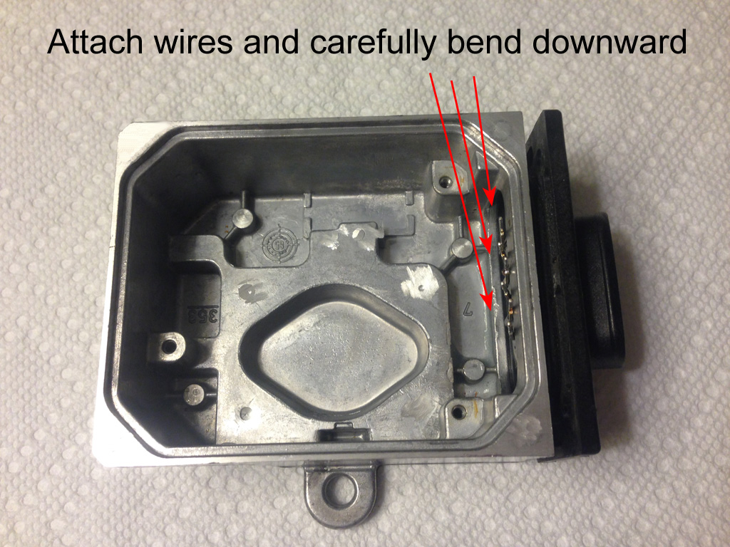
Next, prepare the Bosch ICM box for the wires by cutting the “thin ends” from the back of the black connector (below) and carefully bending the connections downward. Try not to put too much stress on the epoxy seal.
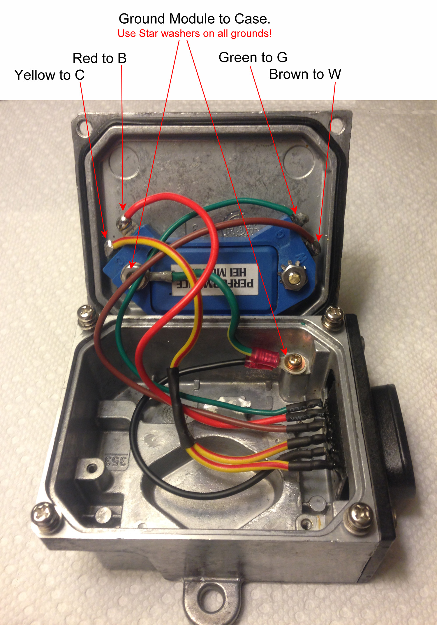
Set your wire color pattern by the illustration below. You will note my yellow wires have a red stripe. (Ignore the stripe! I ran out of yellow wire... :doh") Take note I used heat shrink on every connection and bent all wires downward and away from the HEI module mounting hardware.
Take note I used heat shrink on every connection and bent all wires downward and away from the HEI module mounting hardware.
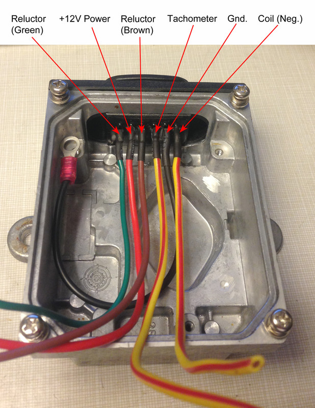
In case any of you are interested, I took the liberty of drawing a pin-out of the Bosch ICM connector.

The wire colors I used are:
Red wire is +12V power to the module and connects to "B" on the HEI Module
Black is Chassis Ground to the HEI module. (and Bosch box)
Green is one of the wires to the Reluctor and connects to "G" on the HEI Module
Brown is the other wire to the Reluctor and connects to "W" on the HEI Module. (both Reluctor wires to the Dizzy are these colors too)
Yellow (2 of these) is output to the coil (Neg.) and Tacho, which are tied together internally and connects to "C" on the HEI Module.
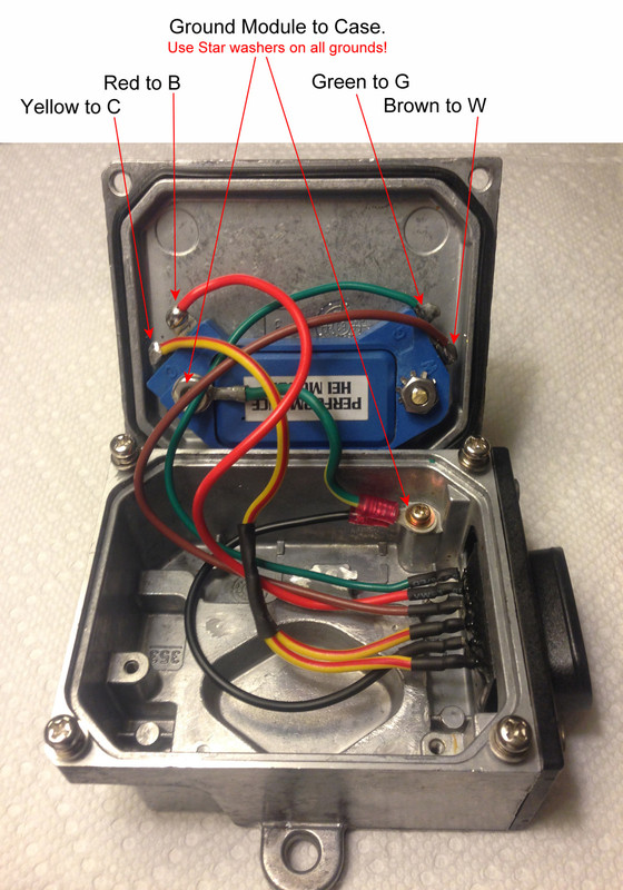
Using the illustration below, attach the wires to the HEI unit’s contact points as shown:
Take note the two green wires do NOT tie together. It just so happens that one of the Reluctor wires is colored green.
I did however tie the 2 yellow wires together (see pic below) so that only one wire is soldered to the HEI’s C terminal.

Once your connections are complete, it’s time to button things up and test your newly created Bosch masterpiece!
Here’s what I got out of mine:
Some observations I’ve noticed:
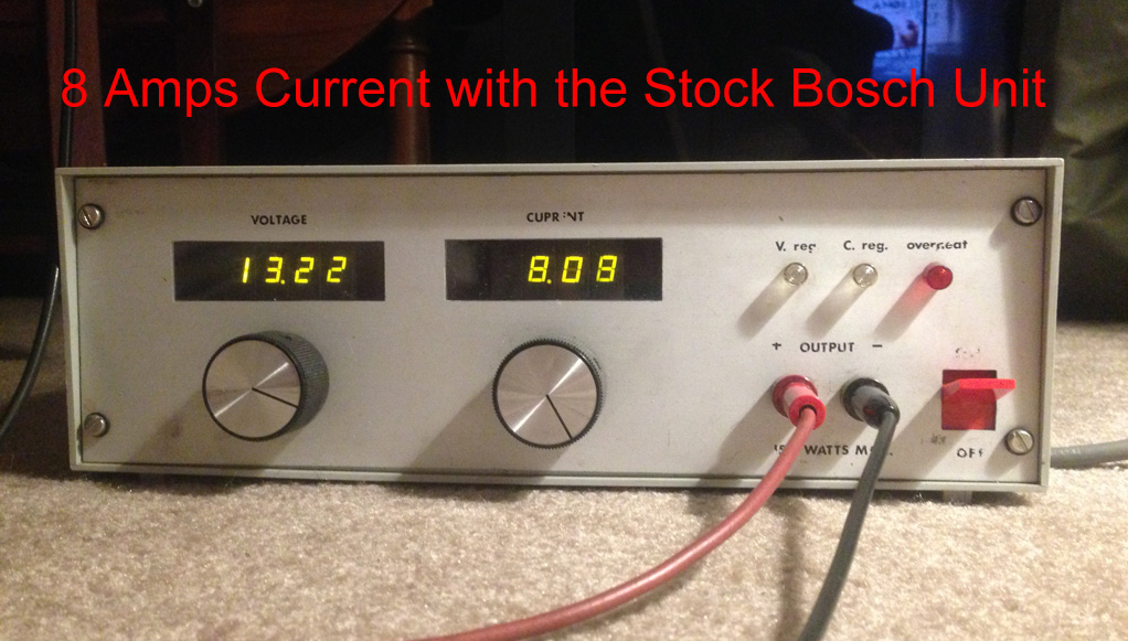
An original stock Bosch setup drew 8 Amps with the ignition on with the Dizzy not spinning.
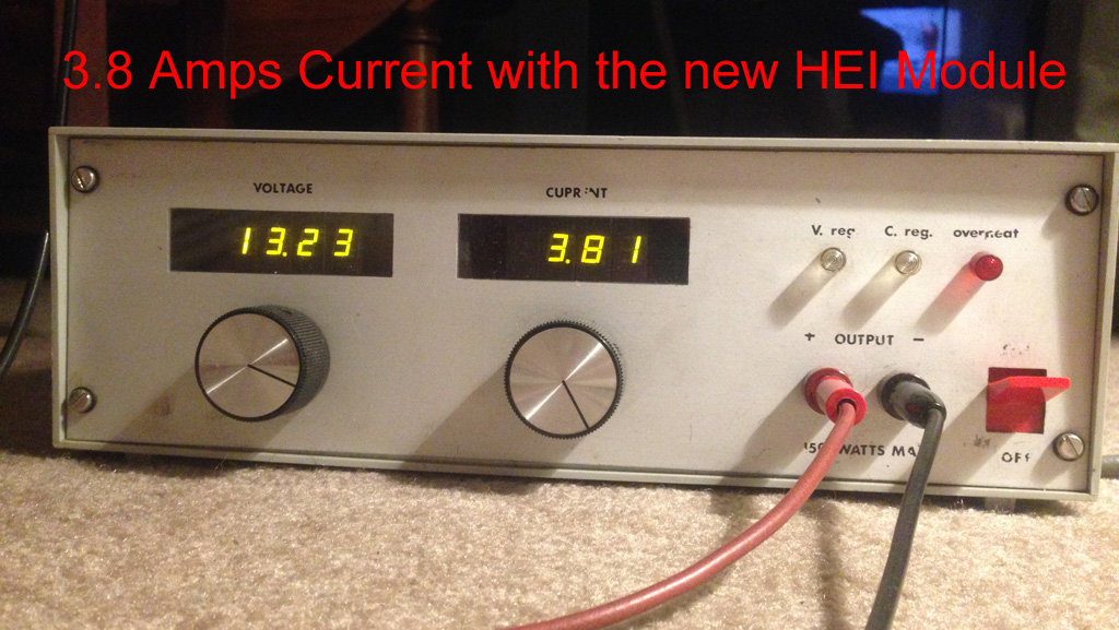
The new HEI / Bosch unit drew only 3.8 Amps under the same condition. A 4.2 amp savings and a cooler coil!
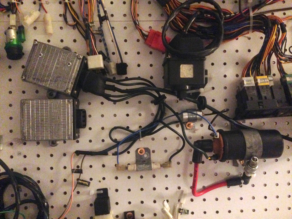
My Setup:
Hopefully, this will help you repair your old Bosch ICM and save big dollars, or help you setup an HEI from scratch.
Bob Brownimp:
Here’s a new twist on a subject that’s been broached a few different ways in past discussions of replacing the Bosch Ignition Control Module. I say “about 10 bucks” but the total might be as high as $15 if you have to go out and buy the misc. items.
I’ve seen photos where some have set up similar devices to replace their ailing Bosch ICM, but what I’m presenting here is a method you can use to actually rebuild your Bosch unit to something that’s actually superior to your existing unit. Plus, you won’t have to modify your wiring harness arrangement in your X1/9.
How superior you ask? For starters, the rebuild will hold spark in excess of 8K RPM, use less than half the current when the engine’s not running (saving your coil and resistor) and produce a spark equal to or better than the original Bosch ICM.
The module that will replace your “old tech PCB” is also by-far much more efficient than the original Bosch unit.
In the likely event the photos disappear from this posting, you can D/L the entire instruction HERE.
Here’s the detail on how to make it all happen…
What you'll need to modify the Bosch: (most of these items should be kicking around your shop)
1. An X1/9 Bosch Ignition Control Module, dead or alive!
2. A Dremel tool with an abrasive cutting wheel and a drill size that will accommodate a 8/32 tap or 5 or 6mm tap
3. A hand drill, or drill press. (recommended)
4. A screw driver, small hammer and a method of pry such as an old wood chisel
5. A tap (8/32 or 5mm or 6mm, your choice)
6. 4 screws for above thread size with a length of 12mm or 0.5 inch
7. 2 tapered oval head screws of the above size with a length 15mm or 0.625”
8. 2 nuts to accommodate the 2 tapered oval head screws
9. 3 stainless star washers to accommodate the above screws
10. Six 16Ga colored wires, 6” long (about 150mm) Preferred colors: 1 red, 1 brown, 1 green, 1 black, and 2 yellow.
11. A four inch 16Ga green wire with a red ring tongue connector attached at each end.
12. A Ring tongue (red color) crimp connector
13. A soldering station, good quality solder, wire cutters, strippers, crimp tool
14. Approx. 6” (about 150mm) of small Heat shrink tubing that will go over the above wire
15. A small amount of “Heat Sink Compound” or thermal conductive grease, found at computer stores or Radio Shack
16. Last but not least, the main component: A GM HEI 4 Pin Performance Ignition Module. (LX-301 or D1906)
Let’s get started…
Looking at the top of your Bosch ICM, you’ll notice four “peened” (domed) aluminum fasteners holding the top cover securely to the module. This module wasn’t meant to be serviced, so removing these aluminum domes requires the use of a Dremel with an abrasive cutting wheel and a little patience. Carefully grinding off the domes (only) will allow you to pry off the cover and expose the inner workings. In my example, I had corrosion under one of the fasteners and it basically froze the stud to the cover. So removing it caused this leg to break off. (See missing stud in lower left corner of photo below)
After the cover has been removed, you will notice 3 screws holding the control board down plus some specific solder points (as noted) that must be separated from their connection points. It will be easiest to remove the screws last.
Using a soldering pencil, carefully separate the six connections from the connector housing from the PCB.
Next, unsolder the three points that connect the board from the power transistor, and cut (or unsolder) the 2 resistor points shown at the bottom of the illustration.
After removing the 3 screws, the board can be extracted. Save one of the 3 screws for later use!
With the PCB removed, we can remove the remaining components inside the box and free up some space.
Using your Dremel tool with the abrasive cutting wheel, carefully grind flat the following areas:
Once those areas are ground flat, you can remove the objects inside and clean up the surface area around the top lip that mates with the top cover.
Below is a photo of an empty box with the mating surfaces cleaned and all components removed:
Next, you’ll need to re-fit the top cover to the box. I am not showing a photo of this, but be sure the top cover mating surface AND the rubber seals are clean.
Place the top cover onto the box. Using the holes located in the 4 corners as a guide, drill and tap new holes so that you can secure the top cover back on. It’s important that you drill the holes straight. In this circumstance, a drill press will be your best friend! Set the depth to about 0.5 inch (or about 13mm)
Installing the new module: (shown below)
This project will use the GM HEI Performance Ignition Module available at auto stores or eBay.
Other part numbers you can use are: LX-301, D1906, GM 1875990 or GM 1894322.
This is a “higher performance than stock” unit.
Prepping the new HEI module:
This unit has locating Tabs that must be removed. Failure to remove these tabs will cause the module to fail from overheating.
These modules are usually mounted to a chassis part or heat sink to allow them to run cool. For this project, we’ll mount it to inside the aluminum cover of the Bosch unit.
You’ll also note there are tabs that extend beyond the inside lip of the cover.
These tabs will be marked and cut as illustrated below. DO NOT BEND the terminals!!
Note there should be plenty of clearance to the connections after cutting as shown below.
Next, we will mount the module to the cover as shown in the illustration below using the module as a guide.
I recommend that you counter-sink the holes on the top (face) side so that the screws do not protrude far from the top surface.
Once the holes are drilled and before mounting the HEI module, coat the back side surface of the module with Thermal conductive grease. Note that this is an important step in assuring good thermal conductivity to the Bosch unit. Omitting this step will cause premature failure of the module.
Very important: When securing the hardware to the HEI module, it’s vital that you use a star washer under each screw.
Insert one end of the 4 inch green wire (that has the ring tong terminal attached) under the post that’s located the furthest away from the large black Bosch connector.
After the module is secured to the cover, I cut the screw threads flush to avoid any sharp points.
Next, prepare the Bosch ICM box for the wires by cutting the “thin ends” from the back of the black connector (below) and carefully bending the connections downward. Try not to put too much stress on the epoxy seal.
Set your wire color pattern by the illustration below. You will note my yellow wires have a red stripe. (Ignore the stripe! I ran out of yellow wire... :doh
Take note I used heat shrink on every connection and bent all wires downward and away from the HEI module mounting hardware.
In case any of you are interested, I took the liberty of drawing a pin-out of the Bosch ICM connector.
The wire colors I used are:
Red wire is +12V power to the module and connects to "B" on the HEI Module
Black is Chassis Ground to the HEI module. (and Bosch box)
Green is one of the wires to the Reluctor and connects to "G" on the HEI Module
Brown is the other wire to the Reluctor and connects to "W" on the HEI Module. (both Reluctor wires to the Dizzy are these colors too)
Yellow (2 of these) is output to the coil (Neg.) and Tacho, which are tied together internally and connects to "C" on the HEI Module.
Using the illustration below, attach the wires to the HEI unit’s contact points as shown:
Take note the two green wires do NOT tie together. It just so happens that one of the Reluctor wires is colored green.
I did however tie the 2 yellow wires together (see pic below) so that only one wire is soldered to the HEI’s C terminal.
Once your connections are complete, it’s time to button things up and test your newly created Bosch masterpiece!
Here’s what I got out of mine:
Some observations I’ve noticed:
An original stock Bosch setup drew 8 Amps with the ignition on with the Dizzy not spinning.
The new HEI / Bosch unit drew only 3.8 Amps under the same condition. A 4.2 amp savings and a cooler coil!
My Setup:
Hopefully, this will help you repair your old Bosch ICM and save big dollars, or help you setup an HEI from scratch.
Bob Brown
imp:
Last edited by a moderator: