K20 project off to a good start, volume 2

Regarding the thermostat and heater hookup, are those NPT threads? You had a machine shop do it or did you do it by hand? I love the idea, but I also like the idea of using the drain plug on the water pump housing as another member here mentioned - but it too would need similar treatment (drilling and threading).
They are 3/8-18 NPT threads. I did it by hand. I had looked at doing the water pump approach, but if I ever needed a new water pump, I didn't want to have to do it again. Plus, I was afraid I would screw up my new water pump.:oops:
 
Hey Rodger - do you have a note of what thread/pitch the Fiat coolant gauge sender was? It seems to be M16 x1.5. Since it has a crush washer I'm assuming straight thread, not a taper like NPT. Can you confirm that?

index.php
 
Hey Rodger - do you have a note of what thread/pitch the Fiat coolant gauge sender was? It seems to be M16 x1.5. Since it has a crush washer I'm assuming straight thread, not a taper like NPT. Can you confirm that?

index.php
I looked through my taps and the largest metric I have is M14 x 1.5, so that must be what it was. I don’t recall exactly.
 
Hey Rodger - do you have a note of what thread/pitch the Fiat coolant gauge sender was? It seems to be M16 x1.5. Since it has a crush washer I'm assuming straight thread, not a taper like NPT. Can you confirm that?
Hussein,

Looking at the MWB site shows there is a 14mm and 16mm version of that sender. The notes in the description regarding model year compatibilty seem conflicting, but they do include the "14mm thread" and "M16 thread" in the related descriptions. So I would say you can use 14mm or 16mm as you wish.
If you are going to put it where I did, get the 14.
 
I got all of the new hoses I needed and wrapped up my version 2 of my cooling system. Since I reverted to using the recirculation port of the K-Tuned upper coolant housing for that purpose, I ordered the Honda hose for that. It fits the K-Tuned housings perfectly.
K20 cooling system revision 15.JPG

K20 cooling system revision 16.JPG


I cut the heater return pipe off just below the coolant housing and connected it to the hose that I ran to connect to the under body pipe. The return pipe takes 3/4" hose, but the heater pipe takes 5/8". I found Gates #18077 at my local O'Reilly's and it provides two solutions with one hose. One end has a 3/4" to 5/8" transition molded at one end that I used to connect the heater pipe to the 5/8" hose. The 18077 is a then a long straight section that ends with a 90 degree bend, perfect for making the connection for the expansion tank to the new thermostat housing.
K20 cooling system revision 06.JPG

K20 cooling system revision 11.JPG

K20 cooling system revision 13.JPG

K20 cooling system revision 17.JPG


Here is how the connection for the heater return and radiator return look connected to the V2 housing.
K20 cooling system revision 14.JPG


Here is the main hot supply to the radiator hose. Yes, it is a lot of hose clamps, and maybe someday if my welding skills get good, I could try fabbing a SS pipe for a lot of it, but not right now.
K20 cooling system revision 18.JPG


Here it is in place. I re-routed how I had the fuel line and wire harness to the injectors to clean things up and to get them away from the hot water lines running under the intake. Much less cluttered than before!
K20 cooling system revision 23.JPG


From the top.
K20 cooling system revision 20.JPG
 
Last edited:
Nice work, Rodger. Much cleaner install now. Thanks for including the hose numbers you used, it helps provide known workable options for layout. To round out the decription of the current revision, the rad feed & return use short silicone 45º 1.375" sections to join above to the hard pipes? Or are they 90º's?

index.php
 
This looks like a great template to take to a speed shop or muffler shop that works with SS, omitting the right side 180 and have it be a 90 to meet a 90° hose. After all the flow is limited by the apertures of all those transitions so going to a hard pipe of somewhat smaller (or larger diameter with swages down to hose interior diameter) won’t hurt and would reduce the drag a fair amount.

16A69CAF-BEFE-49A2-9F41-713BB067B9FF.jpeg


Nice work tidying up further, its like you are a development engineer :) Thanks for the great images, write up and part numbers for the hoses you found to make this. Big thumbs up.
 
Question Rodger...

The aftermarket firewall insulation that most everyone is using, is it sticky backed? The only stuff I'm finding has an adhesive on the back side. I'm ok with that, was just curious.
 
To round out the decription of the current revision, the rad feed & return use short silicone 45º 1.375" sections to join above to the hard pipes? Or are they 90º's?
The hoses that connect to the body pipes are 45 degree 1.375" to 1.25" transition hoses that I got from Pegasus Racing.
 
This looks like a great template to take to a speed shop or muffler shop that works with SS, omitting the right side 180 and have it be a 90 to meet a 90° hose. After all the flow is limited by the apertures of all those transitions so going to a hard pipe of somewhat smaller (or larger diameter with swages down to hose interior diameter) won’t hurt and would reduce the drag a fair amount.
I actually thought about taking that hose down to the auto parts store and seeing if by some stroke of luck, I would find a radiator hose that would replicate the majority of it, but considering how much money I have in that "template" with the hose pieces, joiners, and clamps, I would have hated to just throw that away. The joiners (from Pegasus Racing) are pretty slim, so they really don't create much flow restriction from my point of view. To me, the biggest flow restriction is the upper coolant housing from K-Tuned. The diameter of the inside of it makes the 1.375" of the underbody pipes look like sewer lines. K-Tuned seems to know what they are doing and must sell a ton of these, so I guess the K20 water pump can put out some good gpm rates to compensate for it.

Here are some photos of it apart when I was tapping it for the water temperature sensor. The bore is actually quite small.
K20 coolant outlet 02.JPG

K20 coolant outlet 03.JPG


Here is the whole thing assembled. The top hole is where all of the coolant to the radiator is going through, so much smaller than the 1.25" joiners. The bottom hole is for the recirculation circuit. This shows it with the filler neck attached which I ended up deleting for lack of room.
K20 coolant outlet 06.JPG
 
Question Rodger...

The aftermarket firewall insulation that most everyone is using, is it sticky backed? The only stuff I'm finding has an adhesive on the back side. I'm ok with that, was just curious.
Yes, it is very sticky. The product I used is Dynamat Hoodliner, but there are other similar products out there. Make sure you have it positioned where you want it before you peel the backing paper off, because once it is stuck, it hard to get off and tends to tear, leaving the sticky part on the firewall. A total PITA to remove.
 
The hoses that connect to the body pipes are 45 degree 1.375" to 1.25" transition hoses that I got from Pegasus Racing.

Thanks Rodger. I ordered a pair of RE4538.35-BLACK & one joiner. I forgot the stock hard pipes are only 1.25" :D

I was also surprised at how small the pass is inside the KTuned housing. Mine, which is recirc only, is even smaller.
 
Thanks Rodger. I ordered a pair of RE4538.35-BLACK & one joiner. I forgot the stock hard pipes are only 1.25" :D

I was also surprised at how small the pass is inside the KTuned housing. Mine, which is recirc only, is even smaller.
The stock under body pipes are 1.375” but the K-tuned hose connectors are only 1.25”, hence the transition hose that is ideal for my install.
 
I also started on the exhaust. The base header is a cheapie off of eBay. I went with one for the K20A3 engine as the collector output is 2.5". It seems like all of the K20A2 headers have a 3" output but I plan to use 2.5" components for my system.
View attachment 13650
One of the guys from that works at the body shop is going to weld it for me at his own shop. He has a lot of welding experience and can TIG weld stainless. He cut off the flange and the end of the collector to get rid of the connector.
View attachment 13654
The tubes need to be tilted up from the way they come to allow the collector to exit through rear firewall opening into the muffler bay. He cut them at about the right angle, but it still took a while with my trusty hack saw and grinder to get the angle just right so he can weld the flange back on.
View attachment 13653
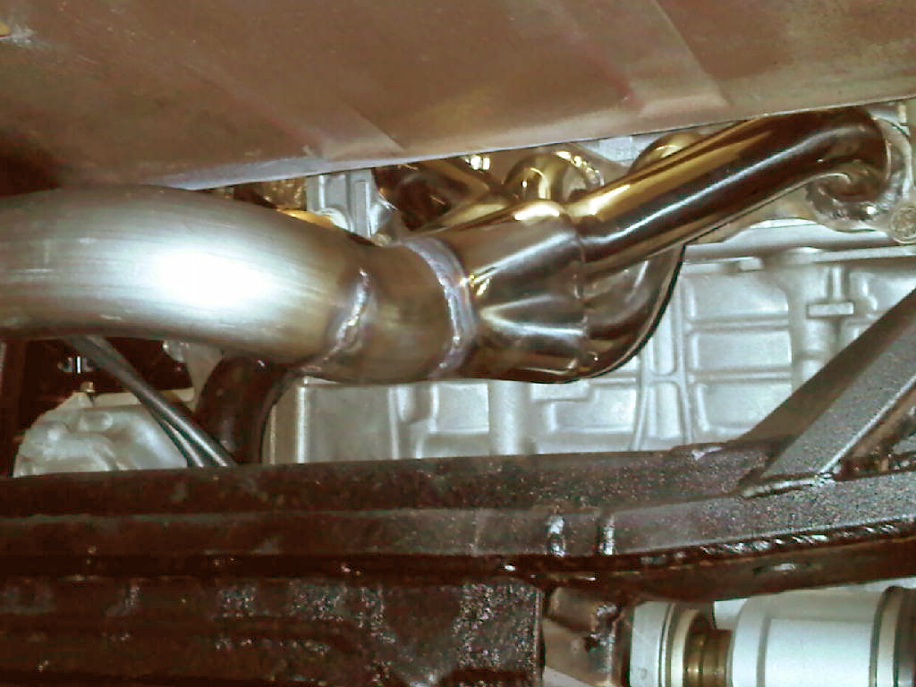
One thing that I did find when I put the flange on the head was that the openings in the flange were about three millimeters too small at the bottom of the openings. I assumed that this would create a fair amount of turbulence and restrict the airflow out so I spent some time grinding them to enlarge the openings to match the exhaust ports.
View attachment 13652

Once I got the angles on the tubes right, I compressed them in a vice to make them more oval shaped like the exhaust ports to get the best outflow.
View attachment 13655

Rodger, do you have any pics or measurements with the header installed? If you have for example, a measurement off the driveshaft to the underside of the header, or relative to the block webbing at a specific point, that would help me make a start on the header layout. I understand if you don't either have the time or inclination to gather that kind of info :D

This pic came from someone's post, I think from an MWB install. Is yours similarily centered in the opening?

K20_Exhaust3.jpg
 
Tim (fiatmonkey) Hoover did one himself - he might still have some good photos from his first build or even one of his two latest builds.
 
Rodger, do you have any pics or measurements with the header installed? If you have for example, a measurement off the driveshaft to the underside of the header, or relative to the block webbing at a specific point, that would help me make a start on the header layout. I understand if you don't either have the time or inclination to gather that kind of info :D

This pic came from someone's post, I think from an MWB install. Is yours similarily centered in the opening?

K20_Exhaust3.jpg
Yes, that is how mine will look, centered in the opening, but I am not going to take the right angle bend to the left. I will try and see if I can make a measurement from the intermediate axle shaft or some other reference point.
 
Back
Top