Volvo C30 AWD Conversion

Nice work. You will be the envy of the C30 set. One of my coworkers has a C30 and is loving this thread.

Coming together, how much longer on this paltry little activity?

:D

Looking forward to the next project where the real re-engineering and Volvo-ication will be taking place.

Hey Karl

I need to be done before Friday. There is an annual "EuroMeet" in Ithaca, NY that I attend, and the plan is to be there in the converted C30. We usually go for a run at Watkins Glen the following day. I'll take the X1/9 if it comes down to it, however I hope I'm done.

Waiting on a few parts, have to install a new front O2 sensor before I put the battery tray, intake piping & airbox back, finish welding the rear exhaust, do the wiring for the Haldex & the fuel gauge that's about it. Will probably take several days after work to do this.
 
Great goal. I hope the parts come in a timely manner, I hate the parts of the process I have no control over.

The company I work for, Steelcase, just had its big show for the year at Neocon in Chicago. I had travelled to the showroom on Monday before, identified a bunch of problems with my products installed in the showroom and started the process of getting parts ordered and planning for parts we would make in the shop versus the factory. I worked through the ones I could do or make happen and got those to the workmen in the showroom. Thursday rolls around and instead of an email with the FedEx shipping number, its an email stating the core part from a vendor hadn’t arrived. Suffice to say the part arrived in the showroom on Saturday at noon for the show which started Sunday at noon. It was closer than I usually allow for.

Good luck and thanks for sharing your skill and most of all your thought process. Impressive as always.
 
Bosch 17332 O2 sensor arrived this evening, so I got that installed & put the battery tray, battery, intake piping, airbox & vacuum pump back in place.

After that, worked on the final piece of the exhaust & the last VBand I have to weld - although this one did come out better than all the others

IMG-8987.jpg


Fit looks good all around, access to the vBand is also good.

IMG-8990.jpg


IMG-8991.jpg


IMG-8992.jpg


IMG-8993.jpg


All that's left is to weld that section to the rear muffler, then cut out a 3" circle for the dump valve :D

IMG-8989.jpg


Just have to figure out what angle to place it at & then brace the pipe to the muffler body - this thing is not lightweight

IMG-8994.jpg


IMG-8995.jpg
 
Last edited:
Pouring rain today. I worked on the wiring for the fuel gauge.

Modified the "Y" harness adaptor that came on the AWD S40, to feed the sender signals, 5V & gnd into an Arduino. No_step on C30Crew Forum wrote some code for me that will average the two inputs & output to a PWM signal, that will connect to the stock C30 gauge feed.

Screen-Shot-2019-06-16-at-4-53-36-PM.png


IMG-9007.jpg


IMG-9006.jpg


IMG-9008.jpg


After that, the rain lessened for a bit, so I went out & removed the rear muffler after marking the intermediate pipe section as best I could for welding. I cut out the hole for the WG VBand flange, so tomorrow hopefully I'll get that all welded up.
 
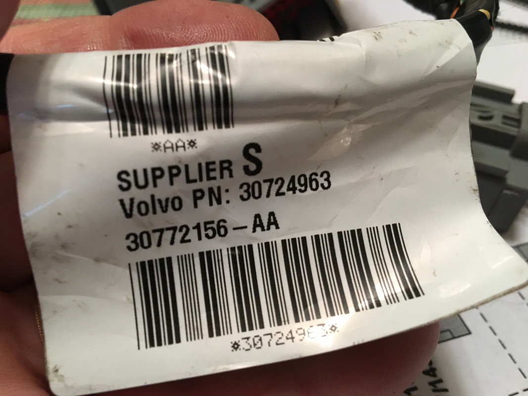
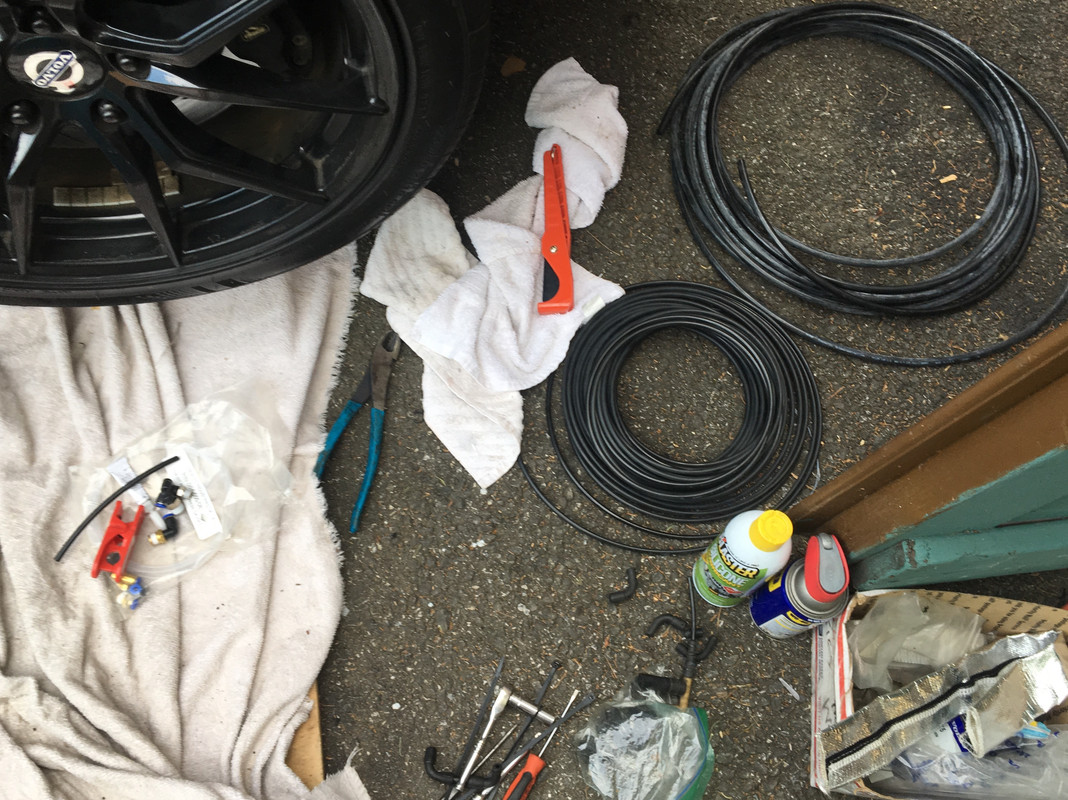
Got all the wiring in today, including the fuel level kit.

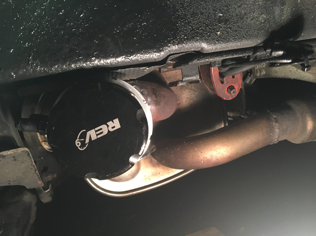
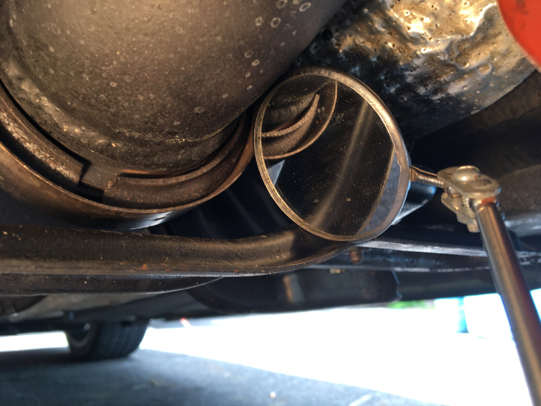
Started & ran it on the jacks, made quite a racket since there is no muffler attached yet & the brakes squeak like crazy with 3 weeks surface rust.

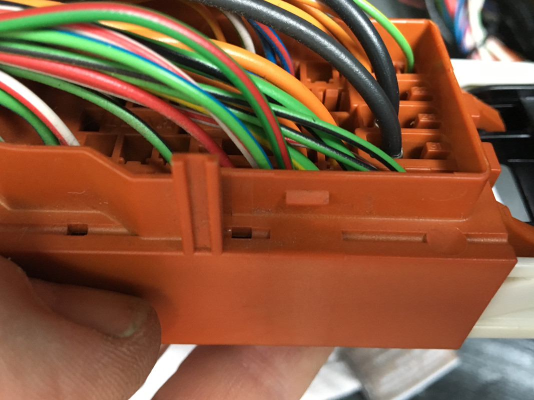
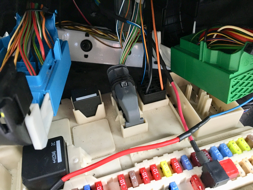
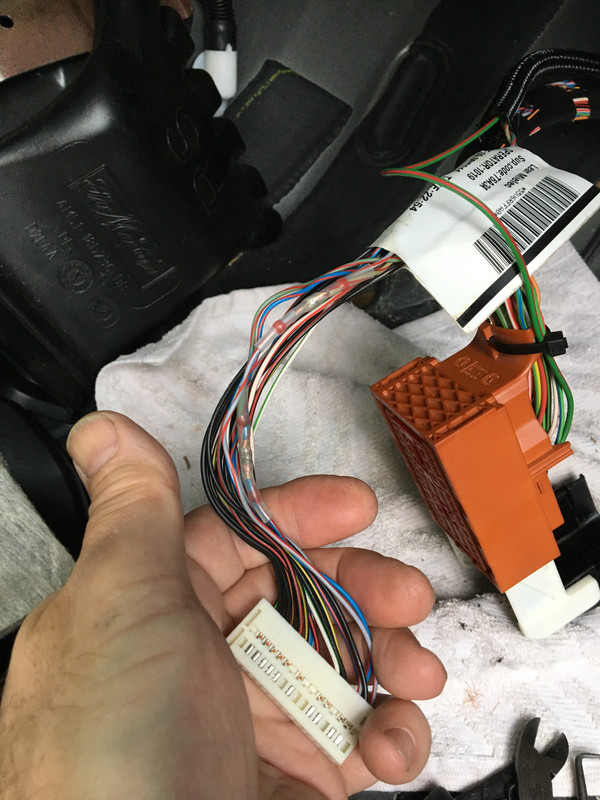
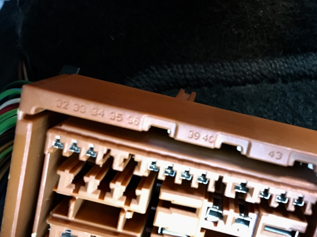
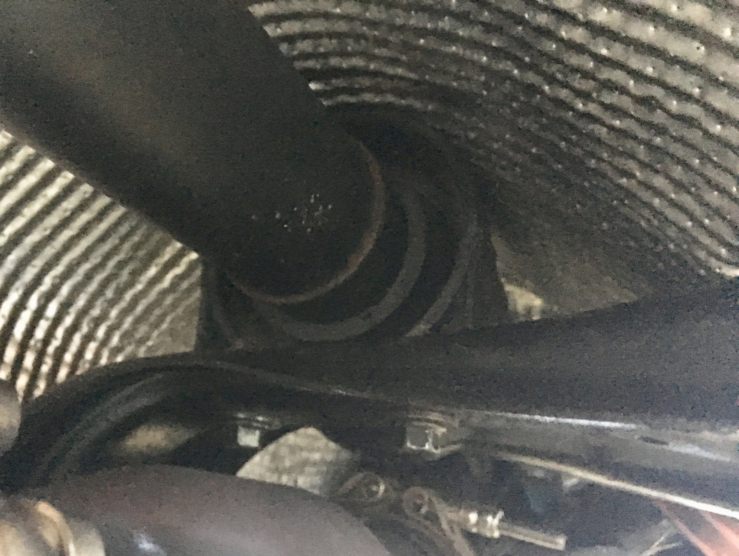
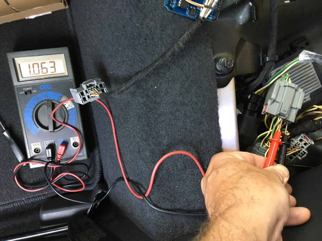
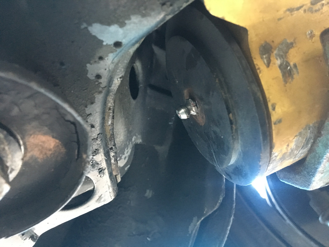
No way to know yet if the AWD is functional, but I did find that the circuit I used for the Haldex is not good - (C:41) - it's live all the time. I only found out because I was under the back of the car test fitting the muffler adaptor & could hear the Haldex pump running, which meant it was running for a good 4 hours with the car off. Hope that's OK. I unplugged the pump until I can figure out what leg to use that has switched power. C:35 & C:38 are open, no idea whether they are constant or switched.

Pin C:41 is where I added the Haldex feed EDIT - pin 38 is the correct feed

IMG-9023.jpg


Green/Red wire, right of center, front row

IMG-9024.jpg


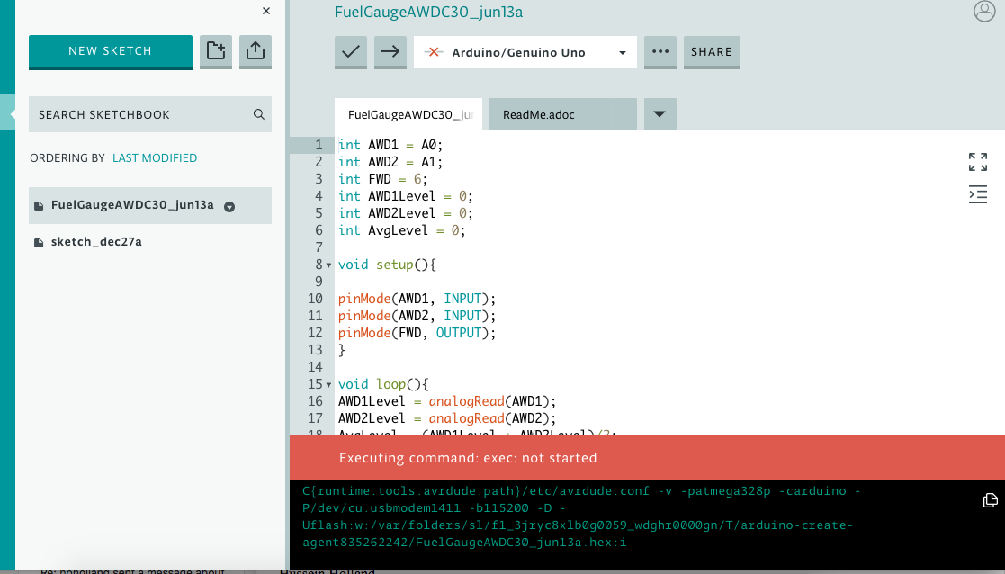
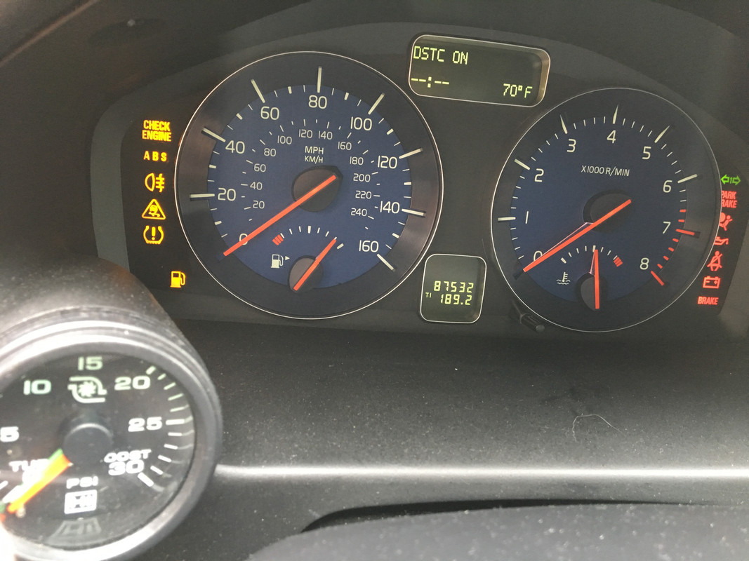
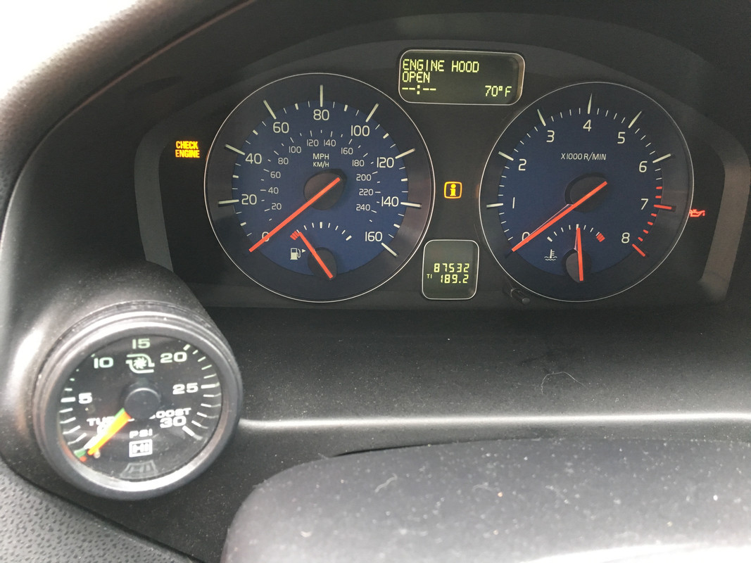
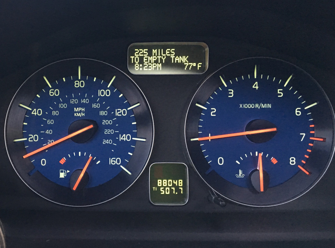
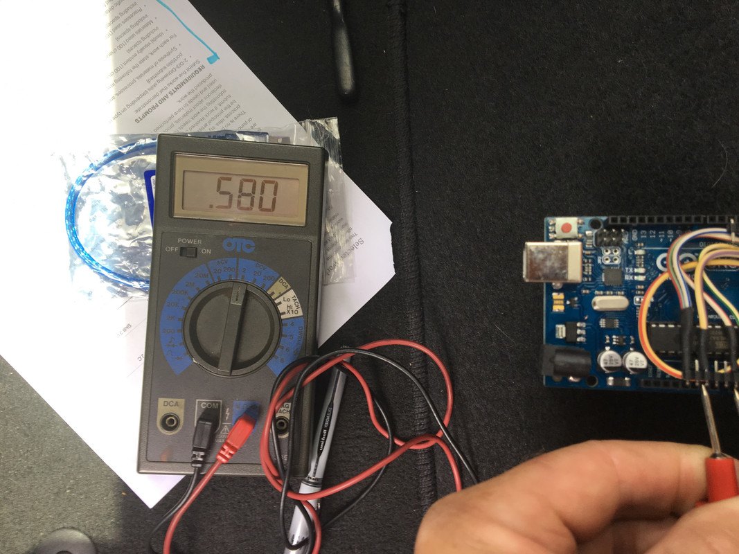
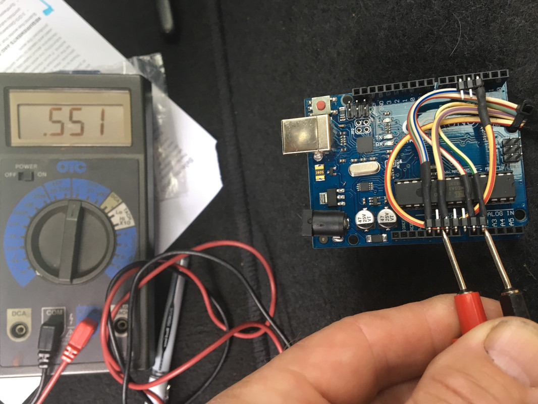
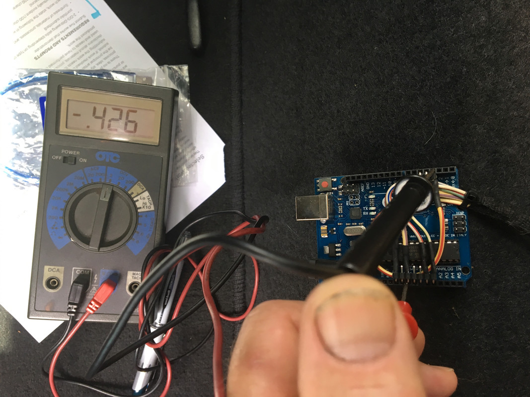
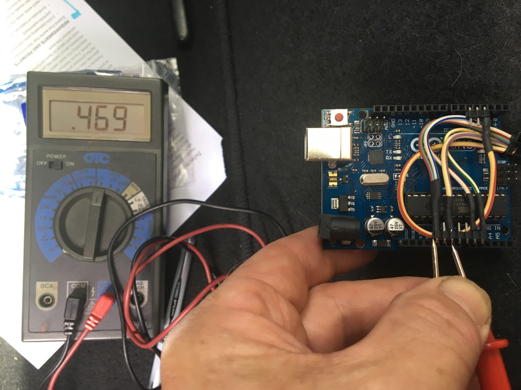
Fuel gauge works, so the circuit is kosher, but the reading is off. Recoding I presume.

IMG-9038.jpg


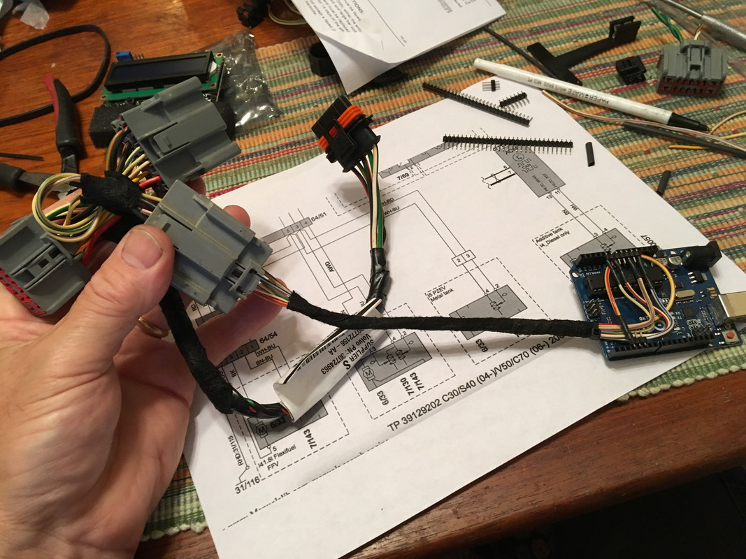
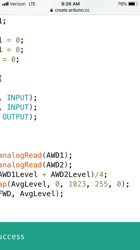
I made a bridge for just the main sender signal & the 5v supply and bypassed the Arduino. Gauge reads pretty much what I added to the tank this evening
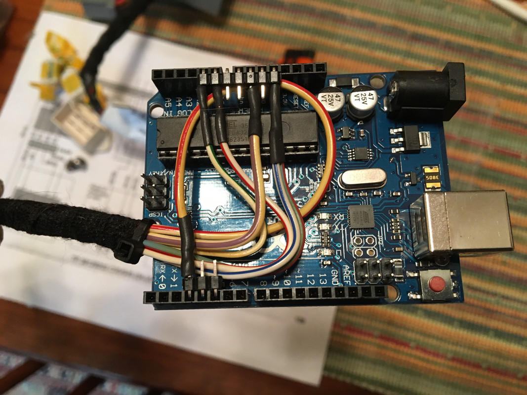
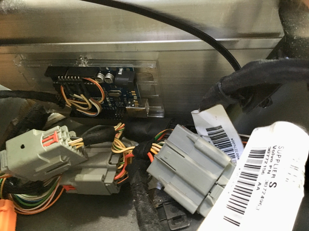
IMG-9037.jpg


Arduino location:

IMG-9033.jpg


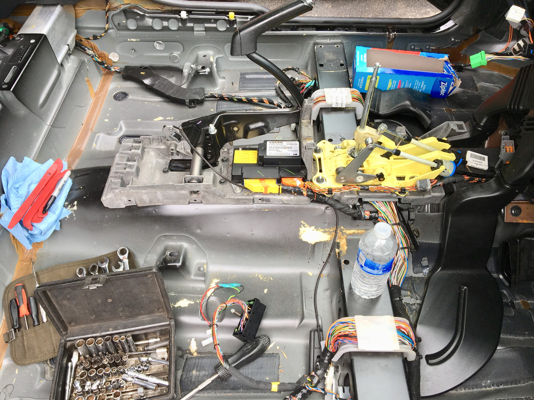
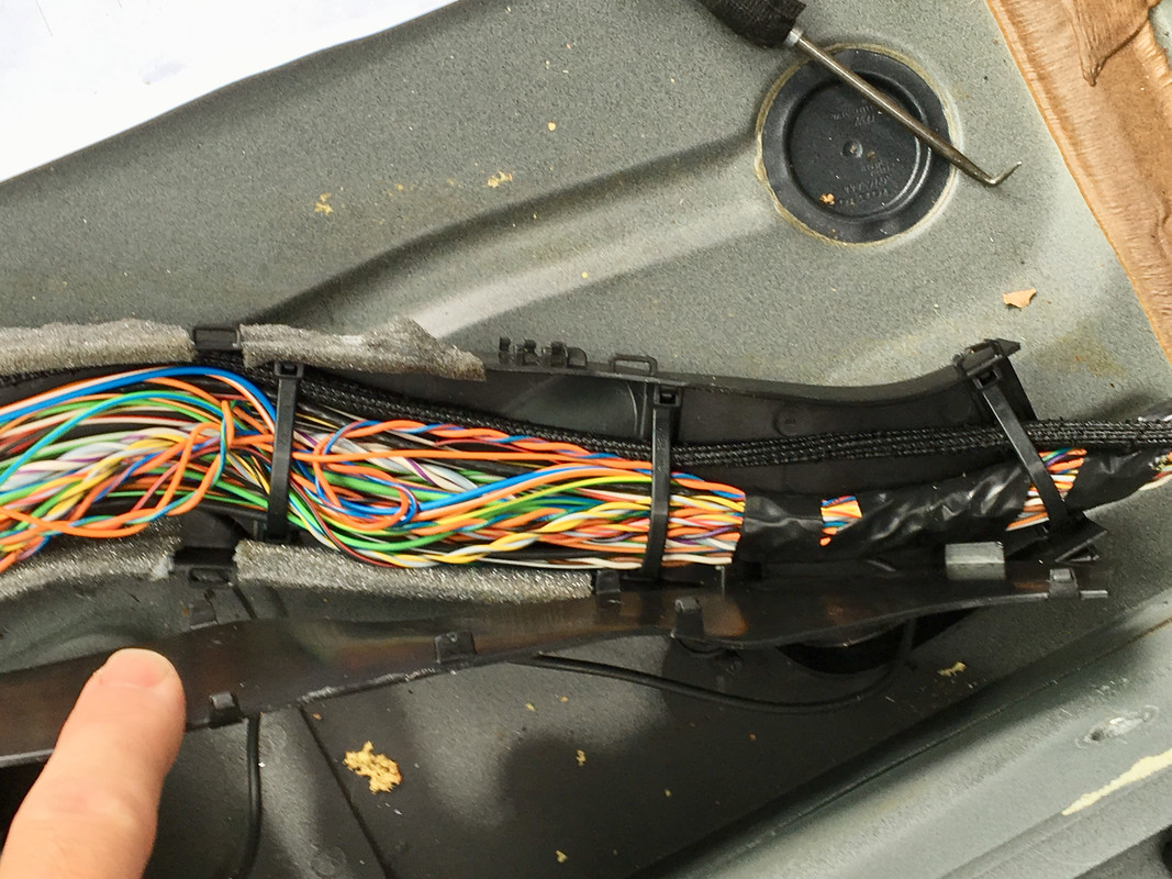
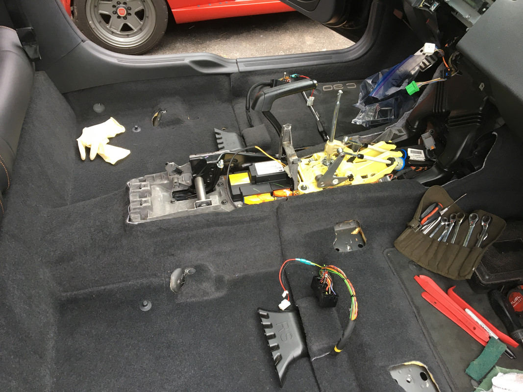
Interior out, wiring being run to match AWD harness layout.

IMG-9011.jpg


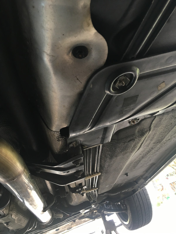
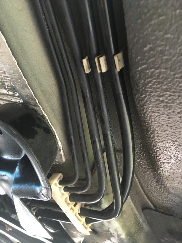
Routing harness along existing. I'm anal enough to route it neatly along original path , but not so much as too open the existing harness & add the AWD wiring for a real factory look :D

IMG-9014.jpg


IMG-9016.jpg


IMG-9021.jpg


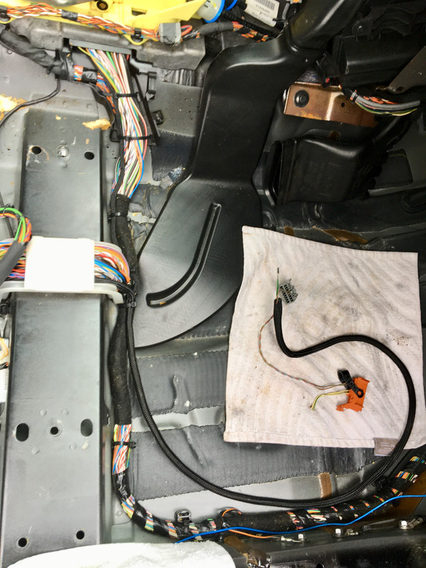
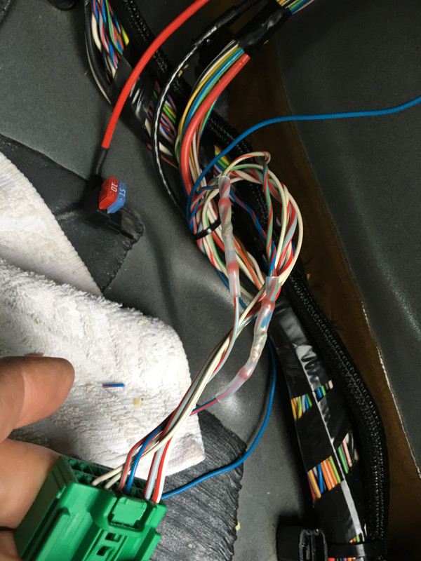
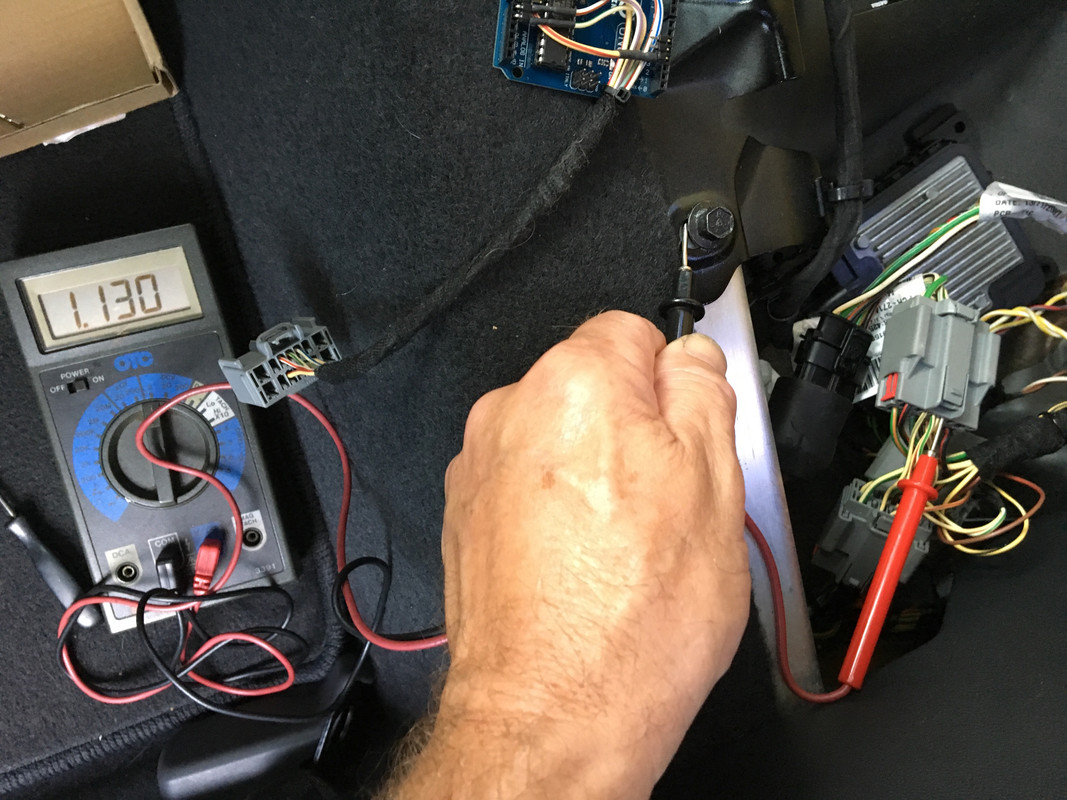
wires added to 64/51 connector (Molex 30700-1147, female) by fuel module (DS under back seat)

IMG-9013.jpg


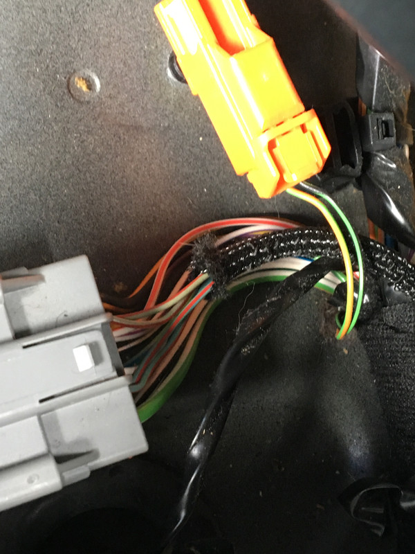
Harness spliced into F:16, F:14. My CEM has different terminals /connectors than the '05, so no way to use the harness as is.

IMG-9025.jpg


And at 64/112 SWM connector

IMG-9026.jpg


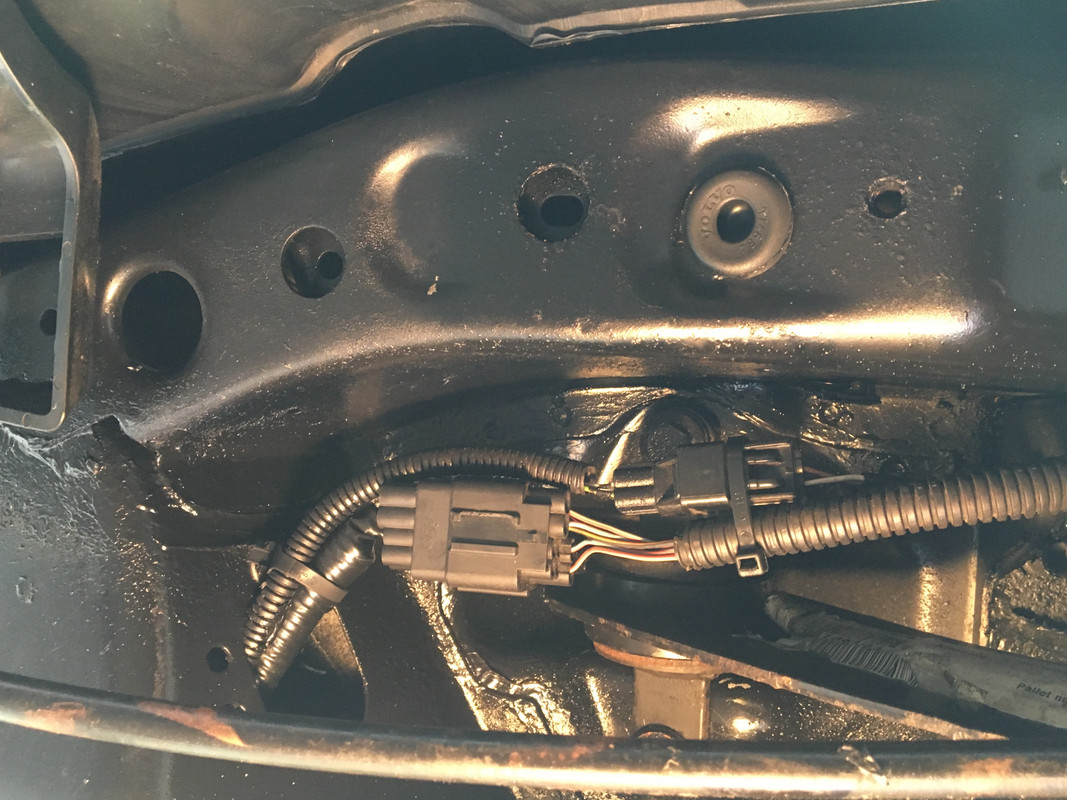
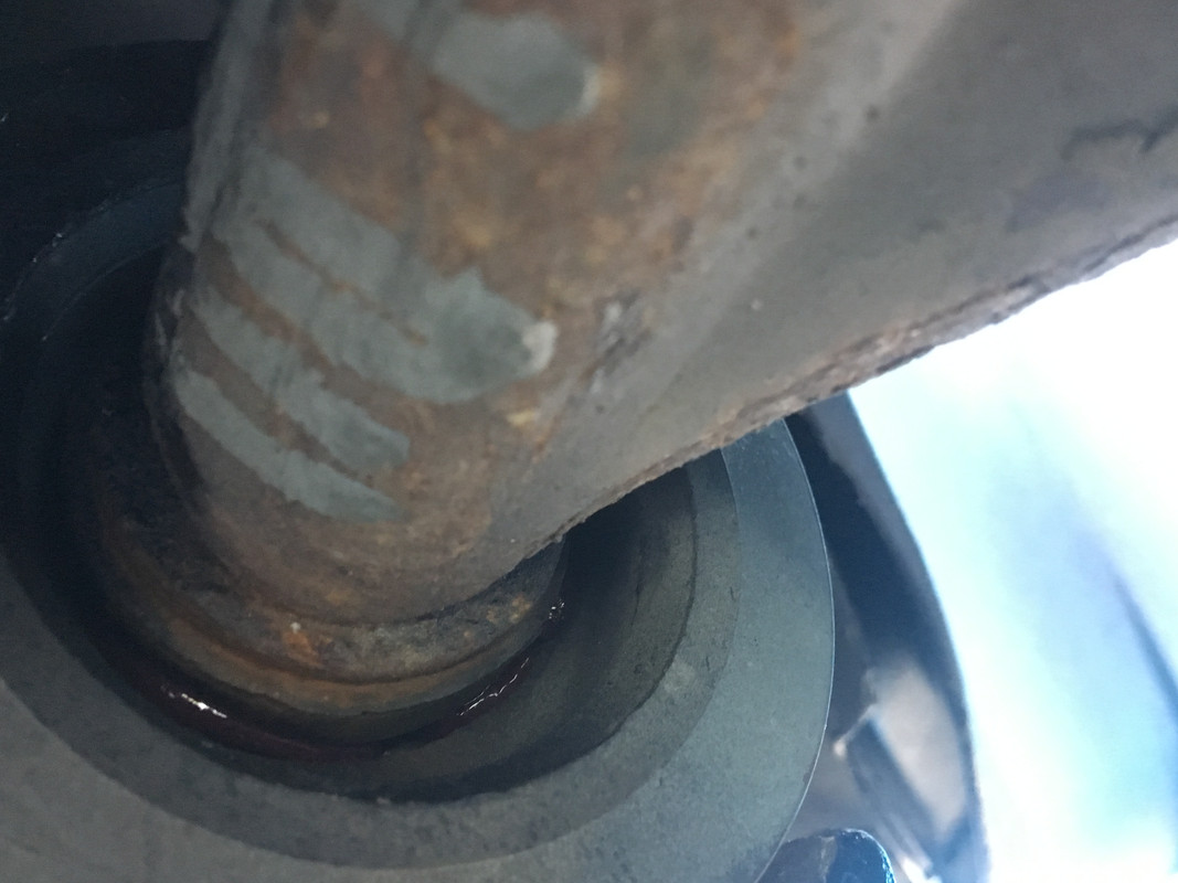
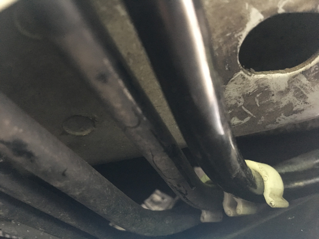
DEM harness (12 Pole Male #1452303-1, YESC 1.5 & 2.8mm series terminals) going through floor, with existing ABS added into it

IMG-9027.jpg


Connectors under pas side forward wheel arch
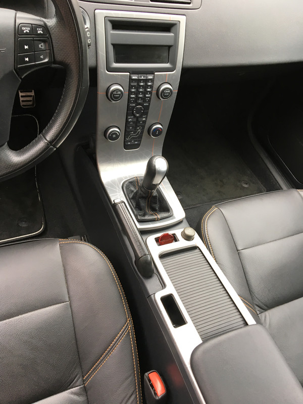
IMG-9028.jpg


IMG-9031.jpg


Carpet back in

IMG-9034.jpg


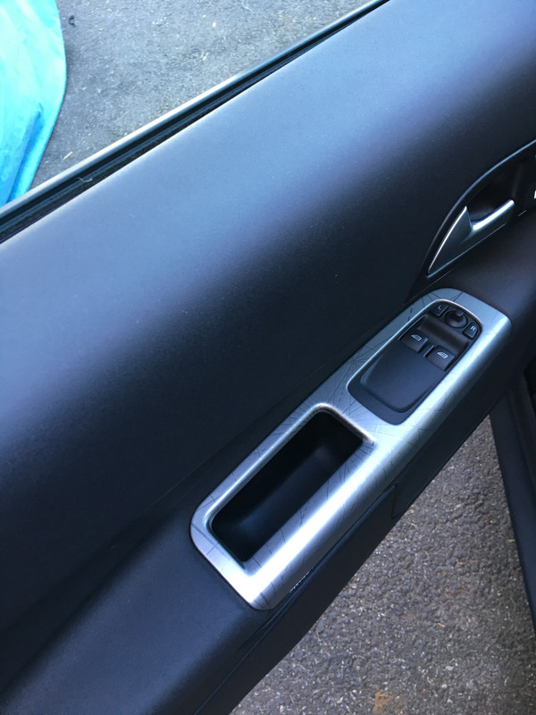
Added the new console trim kit while I had it out

IMG-9036.jpg


Still have to do the door handles.

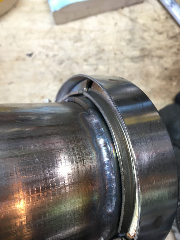
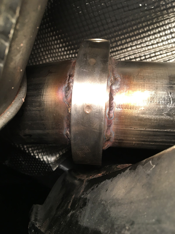
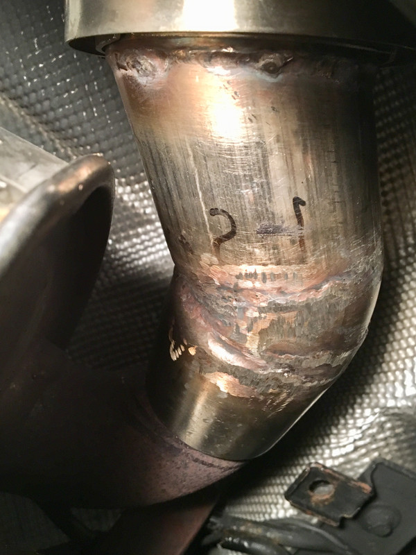
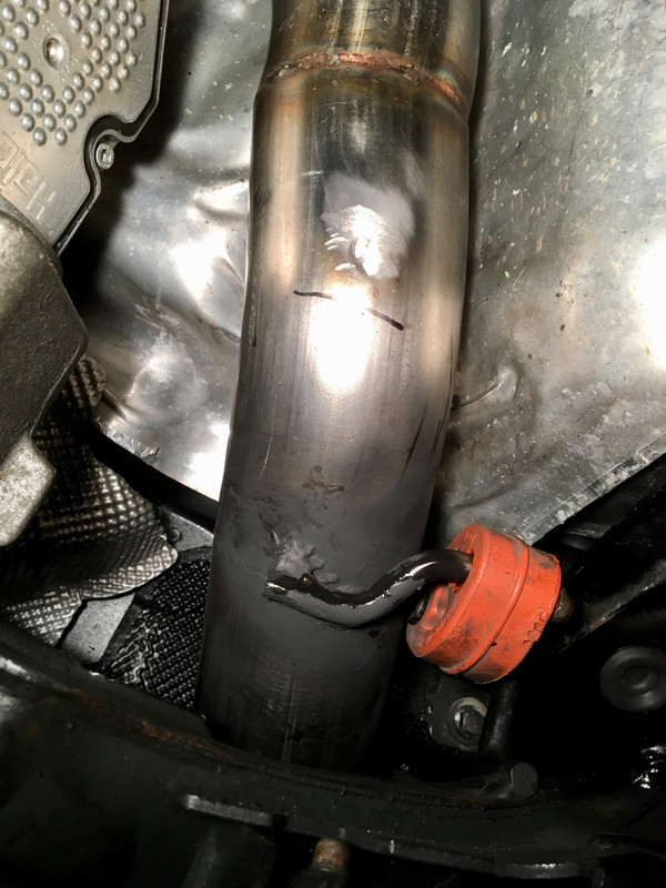
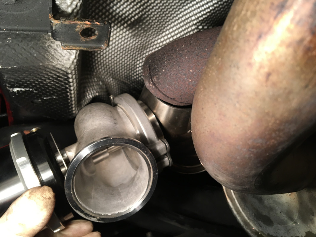
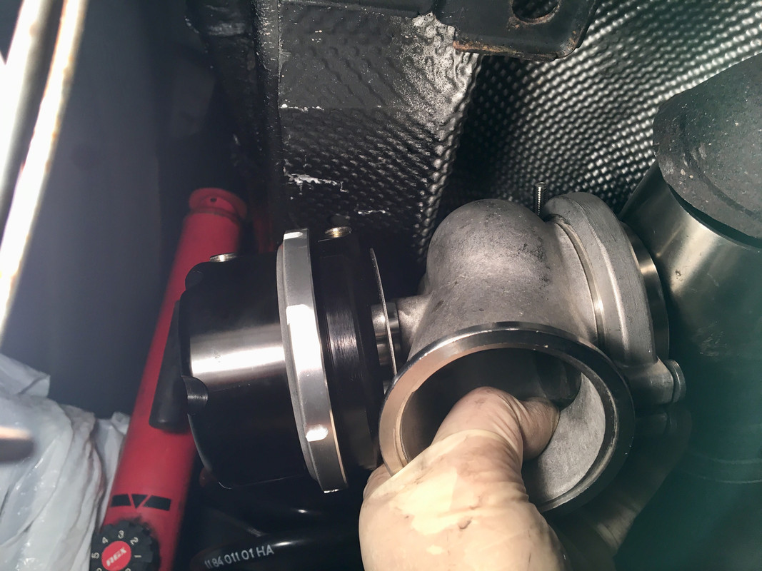
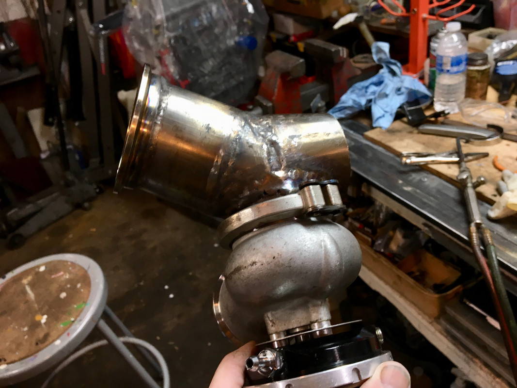
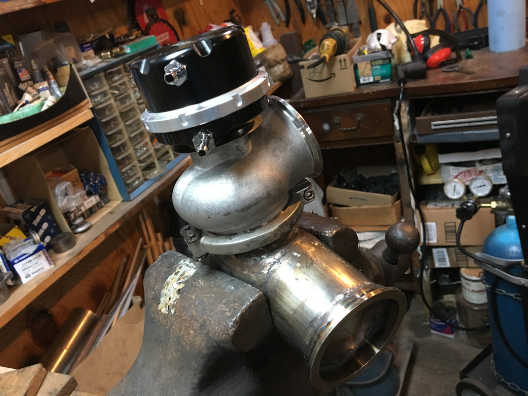
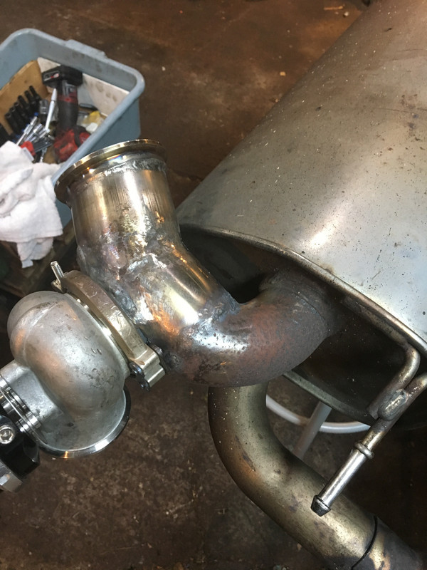
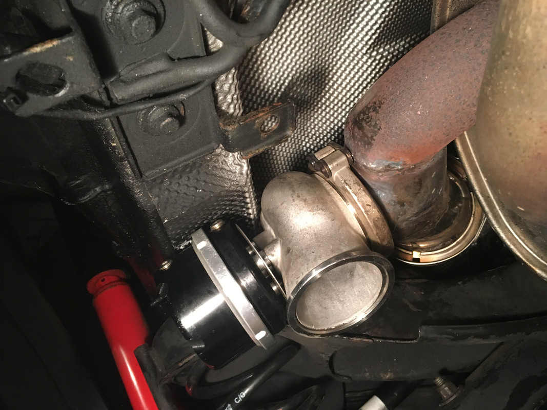
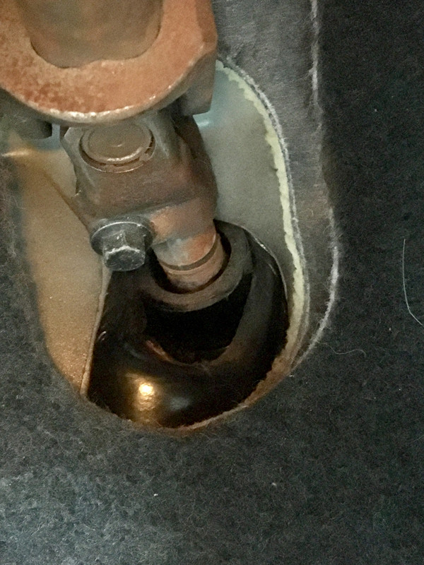
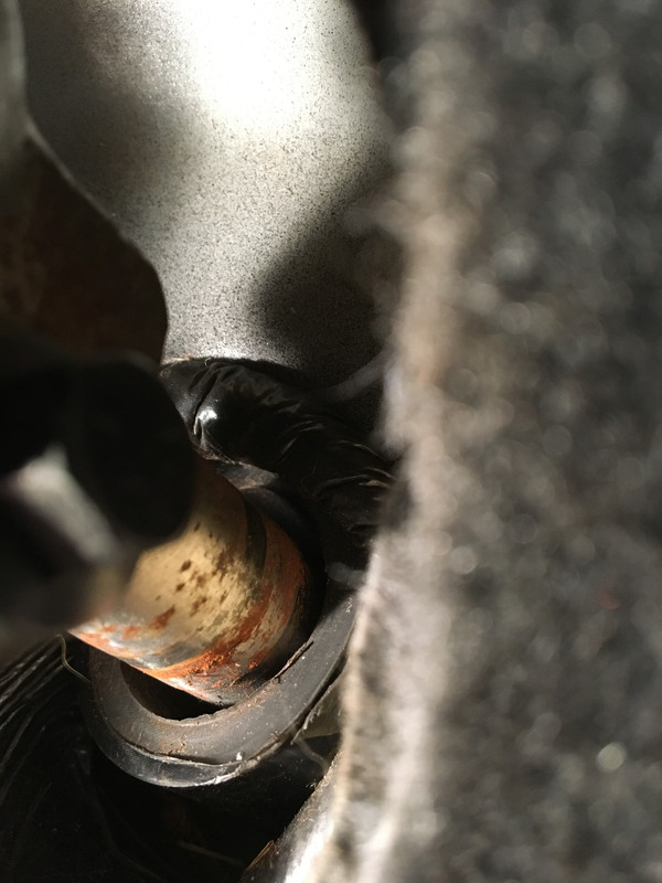
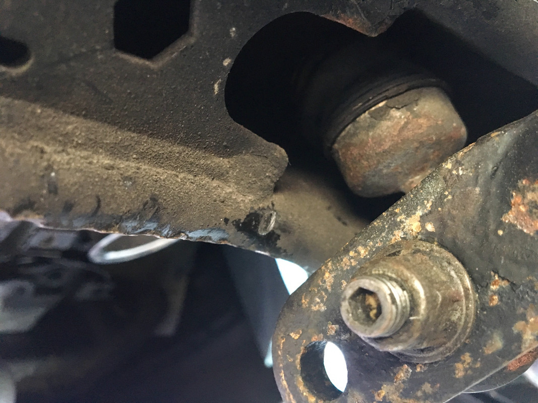
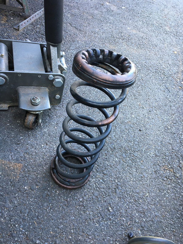
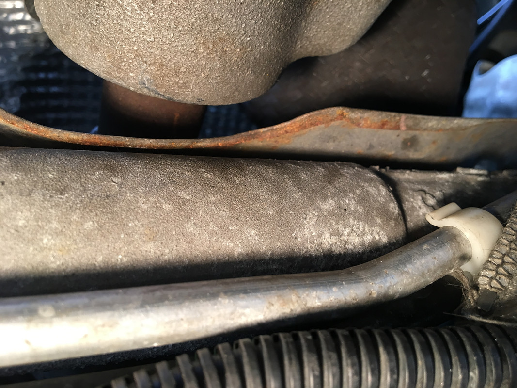
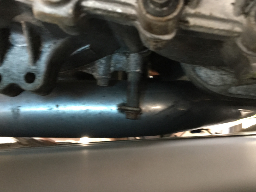
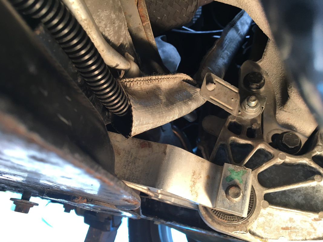
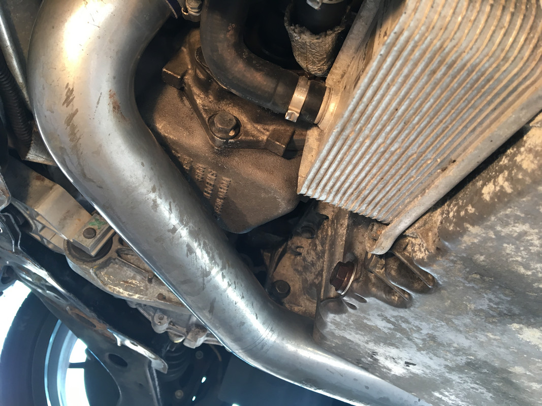
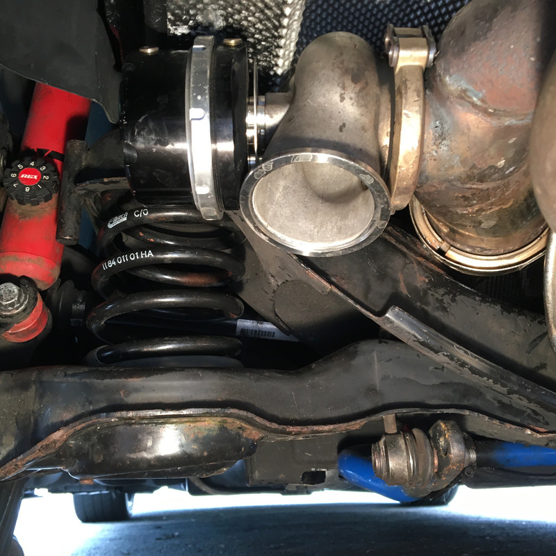
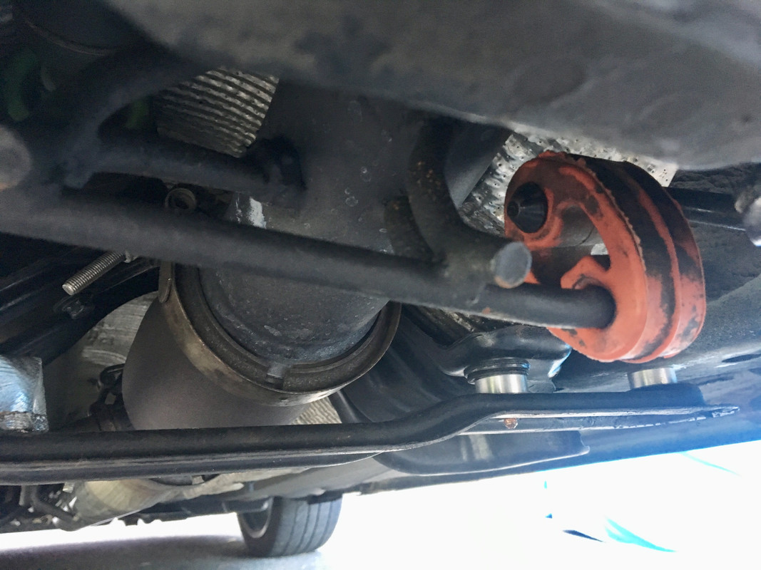
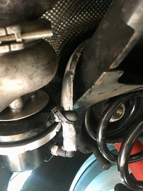
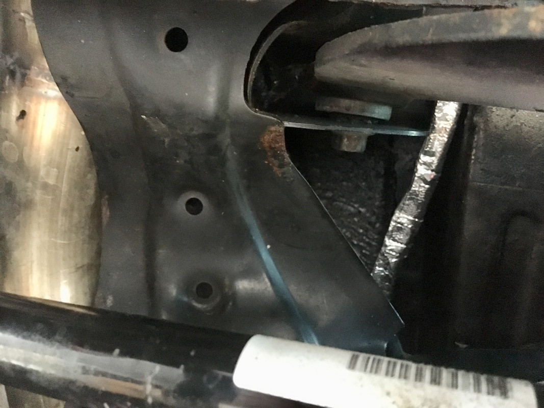
After that, I spent way to many fing hours welding this. It really kicked my butt. Had to make little pie cuts to fill voids on either side & had endless trouble with maintaining a puddle and/or issues with helmet (either too dark, too much flare, etc.) Flange distorted from the heat. I couldn't leave the band clamp on & still get under the lip to weld it at either end. Heated the crap out of it with Oxo-Acetylene & beat the V band clamp over the flanges. Tightened it down & then heated it cherry red from the inside, then beat on it some more. Seems to be flat again now.

IMG-9039.jpg


IMG-9040.jpg


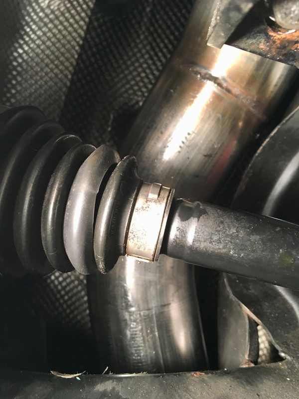
Hopefully tomorrow I get the power supply sorted & the rear muffler welded, or I won't be driving to Ithaca in it on Friday.
 
Last edited:
Figured out I should have used C:38 at the CEM, which is switched power to fuse 51.

Also, the coder noted two errors in his coding that hopefully are the cause of the misread, basically the divisor for the AWD signals was not set to half the averaged amount, and values 255, 0 were reversed, whatever that implies :D. Made the changes below, just have to reprogram the Arduino

53708-BBD-1-CBA-48-A3-88-B2-323-E1879-C1-CA.png
 
Moved the power feed to C:38, that's all good now

IMG-9044-2.jpg


Some horrible TIG welds here. This junction beat the crap out of me. Took forever, and the dump valve flange got badly warped so I had to spend time heating & massaging it back into shape, took way to many hours all told. It's done though, and doesn't leak. Don't have time to actually hook it up before we leave for Ithaca tomorrow afternoon. As it is, I have to jack the front back up, loosen the PS rack, and reset it where it passes into the cabin. I didn't realize it, but I cocked it & the shaft is rubbing on the bulkhead. I drove about 5 miles after getting it all back together around 10, hopefully didn't do any damage to the PS, it did screech.

IMG-9045.jpg


IMG-9046.jpg


Closer to the frame than intended, but clearance is clearance.

IMG-9047.jpg
 
Figured out the problem with the steering rack after a bit.

This was the problem - pinion pushed up into the bulkhead.

IMG-9048.jpg


Back where it should be:

IMG-9052.jpg


I tried loosening the subframe and the rack & repositioning both without success. I decided to remove the torque mount to give myself more room to access the DS rack mount bolt, and that's when I found the problem:

IMG-9051.jpg


IMG-9050.jpg


I had swapped out the bolt for the longer one, because it has the guide pin. The problem was that it was pushing the Rack (rubber) mounting out of alignment.

With that resolved, I added the final piece

IMG-9053.jpg


IMG-9054.jpg


Dove to Ithaca this afternoon. There are a issues to address:

PS tailpipe hits the bumper opening over hard bumps
Vibration under front under hard acceleration - i'm assuming that the engine torquing is pushing the air intake pipe into the metal skid plate, there is so little clearance. I can remove it & confirm whether the vibration leaves when I get home.
Needs alignment. The steering wheel is crooked, and I'm sure it's all out of spec since I had the entire F&R suspensions apart.

Fuel guage is still inaccurate, so further manipulation of the coding is required.
 
O M F G !

Someone definitely has some time on his hands. Super jealous but good on you - wish I could do the same :)

Keep going and posting!
 
Big congrats on making your goal. Impressive as always.

Now it will take another week to go through and perfect all the little issues. It is amazing that you could do all of that and have such a short list of problems.

Wow.
 
Pouring rain today. I worked on the wiring for the fuel gauge.

Modified the "Y" harness adaptor that came on the AWD S40, to feed the sender signals, 5V & gnd into an Arduino. No_step on C30Crew Forum wrote some code for me that will average the two inputs & output to a PWM signal, that will connect to the stock C30 gauge feed.

Screen-Shot-2019-06-16-at-4-53-36-PM.png


IMG-9007.jpg


IMG-9006.jpg


IMG-9008.jpg


After that, the rain lessened for a bit, so I went out & removed the rear muffler after marking the intermediate pipe section as best I could for welding. I cut out the hole for the WG VBand flange, so tomorrow hopefully I'll get that all welded up.


Doing some research on the connectors, as others are asking if I can make more of these. It's like searching for a needle in a haystack. Finally came up with a short list of 14 pole grey connectors that allow for two size terminals (power/gnd + data), and that narrowed down to Molex 30700 H-DAC 64™ series connectors - the female specifically is 30700-1147, based on comparison of datasheet & actual part in my hand. I've emailed Mouser to get the 4 male/female terminal part numbers, as those are what I need more than anything else. The Male housing that mates with the -1147 doesn't seem to exist in any retail form. Molex doesn't list it except as PCB mount, no free-hanging variety :(
 
Could the connections be taken apart and split into some commonly available if not OE connectors? It would seem that breaking it apart could make for an easier solution as a connection is a connection is a connection...

“British machine gun holes. But what the hell; a hole is a hole, is a hole, is what I say.” Sir Richard Burton in Where Eagles Dare
 
Big congrats on making your goal. Impressive as always.

Now it will take another week to go through and perfect all the little issues. It is amazing that you could do all of that and have such a short list of problems.

Wow.

Thanks Karl (Andy and Darin)

I am happy that the list of maladies is short.

Got home from Ithaca this afternoon. 500 or so miles round trip.

IMG-9112.jpg


It was early enough that I wanted to check out the rear knocks - it wasn't the exhaust - the whole rear is too low - the tire OD is level with the wheel arch

IMG-9086.jpg


When I jacked it up & inspected all possible contact areas I found this:

The aftermarket swaybar was smacking the trailing arm due to the suspension drop.

IMG-9094.jpg


I pulled out from storage the original C30 coils (left) AWD coils (center) and Eibach coils (right)

IMG-9098.jpg


3 coil diameters

C30 .455"
IMG-9100.jpg


AWD .485"
IMG-9101.jpg


Eibach .427"
IMG-9102.jpg


I removed the Eibach's & put the C30 coils back

IMG-9103.jpg


IMG-9107.jpg


Not gonna work, though - has "Monster Truck" wheel clearance with those :D

IMG-9106.jpg


So, I took the spare upper seats I had & put them on the bottom of the Eibachs (not these)

IMG-9108.jpg


With that extra height, I got my 1 finger gap back between the tire & wheel arch. Much better

IMG-9113.jpg


I also realigned the rear muffler - by bending the (rubber) mount ears downward to increase clearance for the tips relative to the lower valance.

In addition, I found one of my front vibrations - I hadn't fully tightened (or just not enough for them not to work loose) the front DS bearing mount.

IMG-9104.jpg


I still have to remove the skid plate & see if the other general vibration under accel goes away. That will tell me if I need to rework the charge air pipe under the motor.
 
No sure where to go with this.

EDIT - looked online, the 5V connection is output - I shouldn't have used that. Sender feed V should go to IOref (I believe)

This is with the .5v factory sender feed (found that out today) hooked up to the 5V Arduino input. The sender input and output voltages are all around or under 1V. All values are with about 3 gallons in tank

AWD1 (A0 main sender)

IMG-9116.jpg


AWD2 (A1 secondary sender)

IMG-9115.jpg


Output (PWM3)

IMG-9117.jpg


Input (was .551 not sure why it dropped when I took the pic))

IMG-9114.jpg


After this I found that the ground line wasn't actually connected - it was a dummy wire in the bridge connector.

After I added the ground, I check voltages at the sensor wires. The odd thing is that the voltage is higher when checked to chassis ground vs. the ground wire that also grounds the fuel module, etc.

IMG-9138.jpg


IMG-9135.jpg


At the time I thought it was just becuase I didn't have 5V to the Arduino, so I added a 5V regulator. That didn't help. with 5V supplied, the level input terminals on the arduino also read approx 5V, and the guage was pegged at zero. I unplugged it quickly as I don't know if that voltage is detrimental to the level senders. I have zero desire to drop the tank and pay $$$ two new sender assemblies.
 
Last edited:
The other thing I looked at was causes of the vibration felt up front under spirited acceleration.

I wondering if the engine is too high, as the CVjoint is not centered in the pinion flange

IMG-9118.jpg


clearance for pinion from rack shield

IMG-9122.jpg


No sign of charge pipe contact with skid plate

IMG-9129.jpg


IMG-9121.jpg


Torque mount is also tipped downward

IMG-9123.jpg


Again, no evidence of contact that would transfer vibration

IMG-9128.jpg


No sign of exhaust contact with crossmember

IMG-9126.jpg


On the plus side, everything is stll nice and dry afer the 500 mile drive

IMG-9120.jpg


IMG-9119.jpg


Rear suspension all good now, no knocks or vibrations with the increased spacer height

IMG-9131.jpg


The only thing that makes sense to me, is either the pinion / DS angle is off due to engine height, or the front CV (aftermarket) is subpar and introducing the vibration under load.
 
Played with the arduino after work. Found that I had miswired the output , so I moved that to pin6 from pin 3 , and put the other wiring back to my original layout. With that, level dropped from pegged full to about 7/8, which would be close as I filled the tank yesterday and drove about 35 miles since. I get around 22 in local mixed driving.

Voltage measured at the arduino output terminal was 1v. Completely full should be .6v.

See how it goes over the next 200 miles.
 
Volvo 36000556 axle came last night, so I got that in this afternoon. Seems to have resolved the vibration I experienced under load. I'll know fro sure on the way to work in the morning.

IMG-9157.jpg


Finished up the aluminum trim install on the doors

IMG-9158.jpg


Stripped the old plasti-dip off the grille frame, disassembled the grille & refinished the mesh this time

IMG-9159.jpg
 
Could the connections be taken apart and split into some commonly available if not OE connectors? It would seem that breaking it apart could make for an easier solution as a connection is a connection is a connection...

“British machine gun holes. But what the hell; a hole is a hole, is a hole, is what I say.” Sir Richard Burton in Where Eagles Dare

That doesn't work if I want to make a plugin solution for others. However, the 14pin male is not available, so something else has to happen.
 
Main vibration is definitely gone with the Volvo axle in place. There was still a small vibration. I found a mark on the front carrier bearing support where the VBand was contacting under load. So, I increased the spacing for the support bracket to 3/8", that should do it.

IMG-9161.jpg


While I was under there I retapped the Whiteline end caps for 1/4x24 grease fittings, I haven't greased them since the day I installed them. Squeezed marine lube into them until it emerged on the front side

IMG-9162.jpg


IMG-9163.jpg


After that, I ran the tubing for the WG feed. I used 10mm as a sleeve, & ran 6mm tubing for the pressure feed

IMG-9164.jpg


Used DEI heat shield for the section that is relatively close to the exhaust

IMG-9165.jpg


IMG-9168.jpg


tubing is routed in the existing brake & fuel line channel up to the engine

IMG-9169.jpg


IMG-9170.jpg


IMG-9171.jpg


Tomorrow I have have hook it up to the plenum.
 
Last edited:
Back
Top