
Waynewlw
Wayne Wright's X1/9 V6
With aluminum heads and 9.5:1 compression, pump gas can be used.
The heart the of the project is a 3.8L 90 degree Chevrolet V6 engine (a Chev small block with two cylinders cut off).
Build-up Details
TRANSAXLE
The transaxle used was a 1980 Buick
The transaxle has been rebuilt to handle the horse power of a
blown small block Chev( at least the 80 version can be rebuilt for the power.) It includes the kit plus using the chain from
the turbocharged
The final drive mates to the transmission via a splined shaft. Shaft engagement is about 1-1/2 so it is possible to move the final drive away from the transmission housing and still maintain enough spline to transmit the torque. An adapter was made to rotate the final drive 180 degrees so the transmission. This allowed the full weight of the transaxle to be forward of the rear wheels. It also allowed 4 of the 6 cylinders of the Chev engine to be forward of the rear wheels.
MATING THE ENGINE TO THE TRANSAXLE
An adapter was purchased to bolt the Chev bolt pattern to the Buick transaxle. Many companies make a Chev-to-BOP adapter; however, it is designed to bolt the Chev to BOP bolt pattern for a front engine rear wheel drive car. I even phoned the adapter manufacturer and asked about bolting to the transaxle and was told that the adapter was not designed to be used with the transaxle. I figured that it would bolt up so I could make it work.
The adapter placed the engine approx 0.30 away from the transaxle so I made a collar that fit in the crank that held and centered the torque converter. This also required three spacers to move the torque converter 0.30 away from the engine. A dust cover was made to cover the lower part of the torque converter. Another cover was made to go over the starter motor hole in the transaxle.
PREPARING THE CHASSIS
Remove the cover for the water lines going to the radiator and remove the water lines. Remove the gas tank. Cut the fire wall completely out leaving about 2 below the rear window. Cut out the cross member that holds the forward pick up points clear up to the interior panel. Cut out the rear cross member and all the rear trunk sheet metal. Leave about 2 of the rear cross member sticking out as it will be utilized for the new cross member.
Fabricate a new sub-frame out of two 2x 2x 0.080 wall square tubing. The tubing is placed where the coolant lines were and run the full length from the front pickups to just behind the rear interior panel. Weld out riggers on the tubes at each end that extend as follows: Front to the pick-ups, Rear to the side frame rails. Do not weld up the square tube ends because the new coolant lines(1-3/4 exhaust pipe) will go inside these tubes.
Using 2x2 square tubing fabricate a cross member that takes off where the stock cross member was, utilizing the existing stubs. The rear cross member will be where the engine motor mount will go and it will also be where the rear pick-up and rear A-arm will attach. Do some engineering calculations and estimate the sideways center of gravity of the engine/transaxle assembly. As a final check, place the engine/transaxle assembly on a sheet of plywood with a wooden dowel under the plywood going fore and aft. Balance the engine/transaxle assembly to verify the center of gravity. This will determine where it will go in the chassis. You will find out that the transaxle is fairly heavy and the engine will be offset toward the driver side. Place the engine/transaxle in the chassis and design/build the motor mounts. Two from the transaxle will come off the frame near where the sub-frame is welded to the Fiat frame, and the other will go between the front of the engine and the rear cross member.
REAR SUSPENSION
The rear suspension was the most
challenging aspect of the project. Final
spindle selection was from a 1990 Olds 98.
It is a McPherson strut design.
It turns out that GM didnt change axle splines between 1980 and 1990 so
the earlier axle will mate with the later spline. I suspect the GM full sized cars of today
still use the same spline. Now, the
Next is to work the shock problem. The VW Rabbit shock will slide inside the Olds shock tubing after a little sanding on the Rabbit shock housing. Then cutting the shock towers from a Sirocco and welding them to the Fiat solved the upper end problem. I then used a Tokico adjustable inserts. Used the stock Fiat rear springs cut down. Mating the Fiat upper spring perch to the VW perch took care of the top and reworking the Fiat lower spring perch to go over the VW spring perch took care of the lower end.
Rear A-arms are highly modified Fiat rears. Buy a replacement ball joint for the Olds from a parts house and bolt it to the modified A-arm. Weld fore and aft pick up points, one near the newly installed sub-frame and the other below the new rear cross member. Bump-steer was solved by taking the Olds spindle to a shop and having them ream the tie rod end taper so the tie rod came in from the bottom. Then the tie rod consisted of mating a tie rod from a mid 70s Dodge van to the Fiat inner tie rod. The inner was then placed so you get the lowest possible bump steer.
COOLING AND OIL
Cooling is a major problem if your engine generates any amount of power. Mine does and the special radiator does not keep it cool enough. A special radiator was fabricated. Only the upper and lower mounting brackets were used. The radiator is thicker and required cutting into the front spoiler to make room. 1-3/4 exhaust pipe was used to fabricate the coolant lines from the radiator, through the 2 square tubing, back to the engine bay. With the radiator out it is possible to slide the fabricated coolant lines in the square tubes. Each coolant line was wrapped with a Kevlar type tape for abrasion and cooling insulation. An oil cooler is being added.
The Chev oil filter is on the same side as the transaxle so a remote oil filter was required. It is mounted back behind the wheel well.
When the Chev motor got turned backwards, it was decided to change the pan so the oil pick-up was near the front of the engine(rearward in the car). A lower section from another Chev oil pan was welded to the front of the V6 pan. Baffles were welded. An oil pick-up from a Chev II was used since it locates the oil pump pickup forward on the V8 version. Machine shop welded the pick-up tube to the pump and I built a bracket to hold the pump off one of the main caps. The new front part of the pan is about an inch lower that the stock V6 so it holds 7 quarts of oil. The pan has a tube running through it for the axle to go through.
AXLES
The transaxle uses one idler axle that runs under the engine. A bracket was fabricated to hold the axle in alignment with the transaxle. The bracket was bolted to the stock Chev motor mount. This placed the CV joint close to the block so an after-market small gear type starter motor was required. A 153 teeth flex plate was used. As it turned out, the axle on the driver side fit the installation without any changes. Only the passenger side need shortening. There was enough diameter so new splines were cold machined. This axle is very short. The two rubber CV joint boots are together.
FUEL CELL
Since the gas tank was removed, it was required to mount the gas tank in the front. A 16 gallon fuel cell was chosen. As it turned out it was about wider than the space available, so the forward panel for the cooling fan chamber was jacked forward. A 3/8 fuel line and vent line were run back to the engine bay. The stock Fiat fuel level sending unit was installed in the tank after some of the foam was cut away to allow for float movement. The long Fiat float arm was shortened and the readings are accurate enough for this type of conversion, when it says empty you still have some fuel left. An electric fuel pump and filter are mounted in the same bay as the fuel cell. The fuel cell is low enough that the Targa top still fits in the front. However there is no room for a spare tire, so an emergency inflator/sealer in carried all the time.
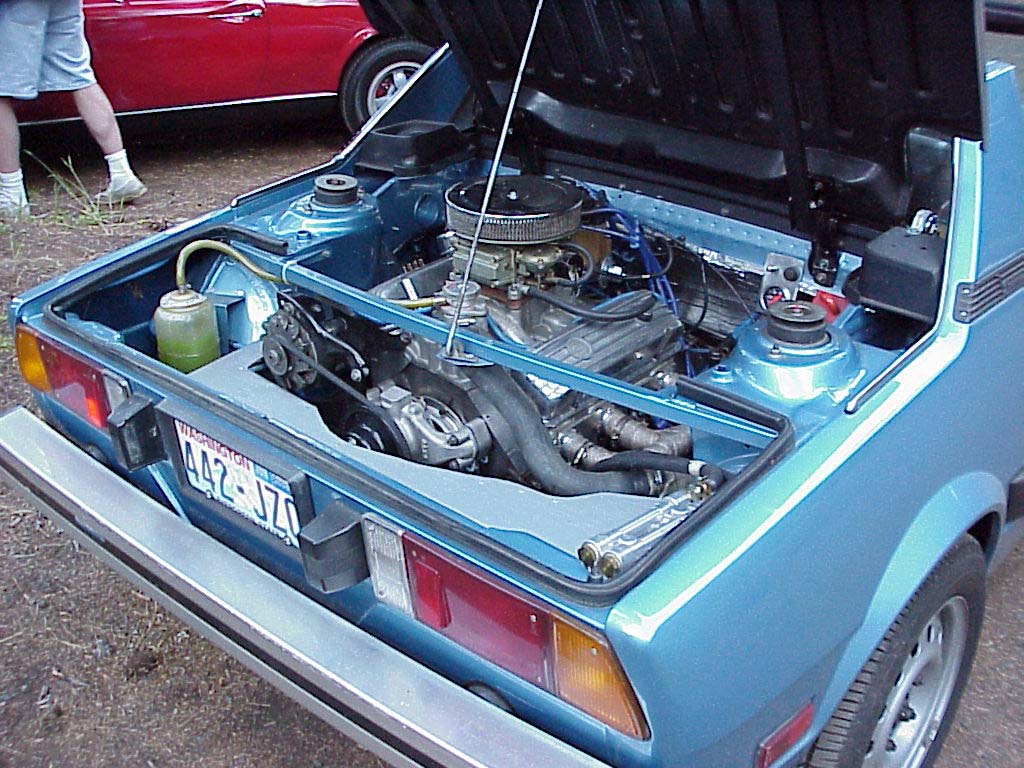
ENGINE
The engine is a 1980 Chev 90 degree V6 out of a Montecarlo. Major work had to be done to the crank because the Chev is internally balanced therefore has counter weights are right in the way where the axle has to go. The machine shop ground some of the counter weights and then I ground some more. Finally got the crank so it would clear the tube in the pan by 0.050. The machine shop had to use Heavy Metal to rebalance. I had all the machine work done in Huntsville by Huntsville Engine since they do a lot of stock car engines. The block was trued, line bored and all that stuff. The bore is 0.030 over with flat top pistons. It calculates out to 9.5:1 compression. Decided to go with the Chev aluminum heads. They come with 2.02 and 1.65 valves and high intake ports. An Edelbrock intake was used, but required the machine shop to weld about to the top of all the runners near the head. I then was able to grind the intake manifold ports close to those of the heads. I ported and polished the heads and intake. A lanati cam was selected. It was intended for the cam to be a streetable cam, but I guess the large valve heads had more affect than thought. As it turned out, it sounds fairly radical. Bought header flanges from Headers by Ed and a pile of U-bends from JC Whitney and proceeded to build equal length headers. Each pipe is 34 from the head to the collector. A Flowmaster muffler for a Buick Grand National was used which produces a fairly throaty sound. Huntsville Engine estimated the horse power around 225. It may have that much because the first time I had it out to an autocross testing day, I stretched the chain in the transaxle. That is when the trans rebuilder found out that there was a special chain for the turbo charged version.

Parts List
Engine
- Engine Block 1980 Chev 90 degree V6(229 cu-in),bored 0.030 over
- Pistons TRW Forged flat top, #L2486F
- Bearings 0.010 Michigan 77, #MS1454P10
- Rings Seal Power, #E-414K 030
- Cam GM Raceshops Marine Hydraulic
- Aluminum Cam Spacer Manley, #42144
- Cam Gear, Bolts/Tab Moroso, #60464
- Lifters Summit small block Chev
- Heads GM Raceshop, Aluminum #14044802 (est compression: 9.5:1)
- Valve Springs Lanati, #73743-1
- Intake Valve 2.02 Manley, #S2256
- Exhaust Valve 1.60 Manley, #A2255
- Guide Plate(4) Competition Cams, #4808-1
- Hardened Head Washers B&B Performance, #3040
- Intake Manifold Edlebrock "Performer", #2111
- Carburetor, 390cfm Holley 4160, #8007
- Carburetor to Manifold spacer Moroso, #64946
- Valve Covers B&M, #65567
- Rocker Studs Dorman 3/8", #710-171
- Carb Fuel Line Adapter to AN flare Russell, #4020
- Oil Pump TRW, #50135
- Oil Pump Pickup ChevII that came with a small block Chev
- Oil Pump Baffle Moroso, #23000
- Oil Filter Relocation Trans-Dapt, 1150
- Rocker Arms Summit 1.5 ratio, #SUM-G6800
- Timing Chain Edlebrock "True Roller", #7800
- Water Filler Neck Moroso, #63420
- Water Pump Weind aluminum, #8208
- Water Pump Pulley Shim Kit Moroso, #6435
- Ignition Module MSD-6AL, #6420
- Coil MSD Blaster, #8223
- Coil Adapter for external coil MSD, #8401
- Distributor Cap Accell, #8129
- Vacuum Advance Accell adjustable, #11031035
- Spark Plug Wires Taylor, #98030
- Engine/Transmission Adapter Transdap, #1150
- Air Cleaner Edlebrock, #1208
- Starter Motor Pro-Start, #PS001
- Oil Pan 7 quart with built in baffles
Headers
- Custom built, 1-1/2" tubes to 2-1/4 Collector
- Flanges and Collectors "Headers by ED"
- U-bends JC Whitney
- Muffler Camaro, 2 in, 1 out
Transmission
- 1980 GM 325 from Olds Toronado
- Built to take 400HP
- Trans Shift Kit Transco, #SK325
- Floor Shifting Unit 1980 Mustang
- Throttle Valve(TV) Cable 1986 Celebrity
Chassis/Suspension
- Motor Mount Pads 1976 Olds Toronado
- Rear Spindles 1990 Olds 98
- Rear Shock Housings VW Rabbit
- Rear Shock Inserts Tokiko gas adjustable
- Rear Springs cut down 1979 Fiat X/19
- Rear Ball Joints 1990 Olds 98
- Rear Shock Towers VW Sirroco
- Axles 1979-1985 Olds Toronado
- Rear Tie Rod Ends at spindles 1980 Dodge Van
- Rear Tie Rod Ends at chassis 1979 Fiat X/19
- Rear Lower A-Arms Custom built
- Rear sway bar Addco
- Front sway bar Bayless
- Front shocks KYB
- Front springs cut down Fiat X/19
- Brake Proportioning Valve Summit, #SUM-G3905
- Radiator Custom built four row
- Starter Push button Switch Summit, G1433
Fuel System Components
- Fuel Cell Jazz 16 gallon, #200-016-01
- Fuel Pump Carter, #P4594
- Fuel Pressure Gauge Summit, #SUM-G3122
- Tip Valve Jazz, #843-008-11
- Fuel Level Sending Unit 1979 Fiat X/19
- Throttle Cable Housing, Engine End 1985 Handa
- Throttle Cable Housing, Chassis End, 1979 Fiat X/19
- Throttle Cable 110 inch bicycle brake cable
- Fuel Filter AC, #G15
- Flexible fuel lines AN type, custom made by Imperial supply
Added Dash Gauges
- Engine Oil Pressure Autometer, #2521
- Engine Oil Temperature Autometer, #2541
- Transmission Oil Temperature Autometer, #2551
- Vacuum/Boost Autometer, #2401