RED X19

About wiring - there are some free wires, can't find where they must go, and as can see from my photos before too out engine from UT - there were not connected then too, of course that doesn't mean they should be like that. That wiring Haynes manual is good, but complicated, bigger problem is that colors are different in manual and there are a lot of white wires :D.

Thanks, have read about cleaning injectors in local e30 forum, anyway helpful info.

that aluminium Magneti Marreli (Microplex) ECU is for ignition.

will read that thread in evening :)
 
I hate wire diagrams, never seem to be easy to read. And like you said, colors don't always match. It could be that some of the loose wires went to removed components (pollution control, accessories, ???), so no longer needed. But more likely they have a proper home.

The link I showed is the profile page for Rachael. She is the only member that I can think of with UT knowledge, but I'm sure there are others. Try contacting her for questions specific to UT. Also maybe start a new thread with title "Uno Turbo in X1/9" (to get attention), then ask questions.

ECU for ignition possibly has a vacuum hose to the turbo system. Reads boost signal (pressure) to retard ignition during turbo boost (prevent detonation). Maybe second vacuum hose from ignition ECU to distributor vacuum can (1st item in picture)?
 
A0CA1654-C274-46E5-B72C-6D4617853EA5.jpeg
A lot of answers got on Facebook from Charlie Whyte, even that I didn’t ask, but he saw was wrongly. Huge thanks to him.

UT intercooler is hard to positon to look it nice. It had a little bent and air leak. Took of one plastic end. Straightened aluminum and glued that plastic part in opposite direction for easier installing.
 
Thank You all for support so far, but I need it even more now to get it running.:rolleyes:

I am very familiar with turbo setups, but general knowledge doesn't help without specific info on EMS & setup requirements. Since Fiat uses very rudimentary systems, it is obvious that the fuel & ign rely on mechanical devices for ign advance/retard and fuel enrichment under load, hence all the vacuum lines...

If you can get a schematic for the UT ign & fuel systems, it will be easy to figure out. As far as vacuum supply, the location in the plenum does matter, as does the size of the porting, IMO. Typically greatest vacuum at idle is at the ends of the plenum. I believe vacuum ports at the TB will respond quicker to changes, which would explain why the ign vacuum is normally drawn off that area. Since the Fiat plenum has the TB in the center, it likely makes no difference which end you use for the Turbo blowoff valve and fuel pressure regulator (turbo specific version?). Having the brake booster port directly across from the TB makes sense, since most cars have that close to the TB in end-mounted plenums. Don't forget your crankcase breather vacuum draw as well, very important on a turbo motor!

Hopefully Rachel will have all the answers for you :D
 
The little bit that I know about it....
View attachment 5868


Hi,
The distributor shown in the left hand picture is not from a uno turbo. It looks like a ritmo/strada/delta electronic ignition distributor.
I use one like that on my NA 1600cc. On the uno turbo 1300 the distributor contains only a rotor arm. There is no advance/retard mechanism or points inside. It only distributes the spark from the coil to the individual plugs. I seem to remember the distributor for a 1600 Tipo is the same but I can't be sure as I don't have one to hand.
The ignition control is via the ECU circled in blue.
The pipe coming from this ECU is for the vacuum/boost sensor in the ECU.
The ignition ECU, blow off(bypass) valve, boost gauge and waste gate actuator (not shown ) all need to be connected to the plenum chamber to sense vacuum/boost/over boost.
Ignition control is via a sensor on the crank pulley for TDC and one mounted on the gearbox bellhousing counting teeth on the flywheel for engine speed.
The distributor is mounted on the end of the camshaft on the 1300 and on the 1400 it is in the regular block mounting. Again on the 1400 the distributor has only a rotor arm inside.
There is a separate ECU for fuel, built into the air flow meter on the 1400 and separate on the 1300 . The fuel pressure regulator also needs to be connected to the plenum as this raises the fuel pressure under boost.

The picture of the plenum with the yellow circle appears to show a highbred setup. The plenum is 1300 but the AFM is mounted where the distributor should be on a 1300. I assume the distributor is block mounted as on a 1400.

Mkmini I highly recommend you get a copy of both the red and orange covered Haynes manuals for the Uno. Although not perfect in their content they will give you a good idea of what goes where and does what. I say get both because each contains info and diagrams the other does not have. Orange is 1300 only and red is some 1300 and most 1400 info. As I said they are by no means perfect but...

Good luck
Andy
 
F5A89B5F-0B19-417E-BD59-E64AAB9CD80D.png
C087E6EC-76EC-4A56-BF22-E583A39D8069.png
Thanks a lot, about distributor and vacuum/boost hoses was already informed.

Luckily had distributor on spare UT engine. But am waiting for new arm and cap.

Today had to things for money.. Will do all what I can figure out and whate have been informed about on loom.

There left just a few free wires on loom. “Living” in garage doesn’t help for logical thinking- I can check those wires with multimeter to find out where does they go on fuse box..

In pictures are gearboxes from X19 and UT, what for is that hose?
 
The photo of the blue X1/9 above shows the common problem with the Uno Turbo swap - the air filter gets hot air straight off the intercooler. You may as well do without the intercooler in this situation! You need to use some ducting to get cold air to the air filter. Better still, install a water-air charge cooler.
Hi Rachael, some guys on Facebook answered a lot of questions.
1. On this X19 absolutely all wiring and electrical devices is from Uno Turbo mk1 1985. There is non wire left from X19. Only electrical things from X19 are front and rear lights. Rear ones are connected. Front am going to connect when car will be running.

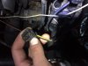
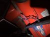
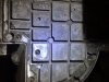
2.There left few wires/plugs that I can’t find where to plug. One of them seems to be unplugged when bought a car. Those plugs are showed in photos.
A•black and yellow, under heat insulation black wires becomes a screen for yellow, like on radio antennas..
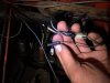
B•brown/red round plug fits only in one place, but I doubt, because brown/white that fits there doesn’t look original.
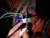
C•wires that go to fuel relay:that thick yellow one. It has wire in middle and screen around. That screen isn’t connected anywhere on relay, Didn’t try to find what is happening on the other end of this wire.
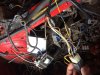
D•alternator/battery charging warning wire. There is no more options left-changes color from grey to grey/black. This could find out when car will be running. (In last picture you can ser where it could be connected- behind plug for fuel injectors fan plug)

3.dizzy found on spares engine, cap and roTor arm will get on Wednesday.
4.Guys on Facebook told that my ignition coil is from mk2 uno turbo, and it looks so from Haynes manual.
Could this coil work? Plugs fits, because they are modified before.

That is all at engine bay.

One thing that I don’t get it, why Fiat(or previous owners) have put
• +wires in red color, but some in brown
•and same are some - wires in engine bay:brown

Thanks for helping :)
 

Attachments

  • 2C4BB4F3-C176-4F43-8C22-FCEC9CFA0636.jpeg
    2C4BB4F3-C176-4F43-8C22-FCEC9CFA0636.jpeg
    211.4 KB · Views: 161
  • 3D309E09-CB62-4B7C-AF0C-6FFF803C10F1.jpeg
    3D309E09-CB62-4B7C-AF0C-6FFF803C10F1.jpeg
    216.3 KB · Views: 174
  • 8B260A5E-309F-49C0-8C87-A8BE3B60CF48.jpeg
    8B260A5E-309F-49C0-8C87-A8BE3B60CF48.jpeg
    241.4 KB · Views: 166
  • ED372FC2-5AB9-458E-A397-1423F02623BF.jpeg
    ED372FC2-5AB9-458E-A397-1423F02623BF.jpeg
    320.4 KB · Views: 329
  • C44DC355-74E5-4520-8539-D277435884E6.jpeg
    C44DC355-74E5-4520-8539-D277435884E6.jpeg
    198.6 KB · Views: 187
Hello Janis, I don't know what help you have had on Facebook as I am not allowed in that particular group. I have my own Facebook group. I am told the most helpful thing they did was to point you back here!

1) The Uno fusebox and wiring loom can be used in the X1/9. I'm using them in my Montecarlo and a Lancia HPE that I'm rewiring. Happily Fiat have standardised on many wire colours for all their cars:
Green for right main beam
Green/black for left main beam
Grey for right dipped beam
Grey/black for left dipped beam
Light blue for right indicators
Light blue/black for left indicators
Yellow/red for right front and left rear side lights
Yellow/black for left front and right rear side lights
Red for brake lights
White for reversing lights
Brown and red usually for unfused 12V supplies
Black for ground
Black/violet for some grounds too

Unfortunately some wire colours appear in more than one place around the car, so you have to know which circuit they are in. Generally no colours are repeated in the same piece of loom unless they are actually connected together.

You will need three additional changeover type relays and associated wiring for the headlamp pods.

2) A- The mini-timer plug may be for the RPM sensor on the flywheel. The two VR sensors and the knock sensor all have shielded cables to prevent interference. The shield should only ever be grounded at one end, usually at the ecu end. Check the RPM, TDC and knock sensors are connected correctly, it's *very* easy to mix them up. Check the wire colours to each mini-timer plug and its socket are matching.
B- That looks more like grey/red to me. Grey red is used by both the Microplex (overboost switch) and Bosch (injector control) ecus so I'm not sure where it connects. You need to trace it back to see which multi-plug it goes to. Brown/white is a Microplex coil control or Bosch throttle switch wire, again it needs to be traced back to the multi-plug.
C- This is a shielded wire connected to the coil -ve terminal, where it also connects to a shielded wire to the Bosch ecu. This allows the relay to sense the coil sparking when the engine is running so it knows to switch on the fuel pump. If the engine stalls, the relay senses the loss of signal and stops the fuel pump, even if the ignition is still switched on. Again, the shield should be grounded at the Bosch ecu end only - the two wires' shields are connected together at the coil but not grounded there.
D- The grey/black alternator sense wire should be grey/black all the way to the instrument panel, it may have been "bodged."

4) Mk1 and Mk2 coils have different igniter modules but the wire colours all have the same function. As long as the wire colours are on the correct pins the coil will work, seems like the previous owner sorted that for you.

I see you are putting your air intake in the boot, good idea. Please don't use that plastic fuel filter anywhere in the fuel circuit - it isn't safe!

Cheers R
 
One thing that I don’t get it, why Fiat(or previous owners) have put
• +wires in red color, but some in brown
I know, right? And to make it even more difficult, all of the older German cars that I like to work on use 'brown' for the grounds...just the opposite. I have to change mind set every time I work on a different one of my vehicles.

I'm glad someone else can help with the wiring issues. It looks like there have been a lot of modifications to the harness in the past (as with most older vehicles)...make the job so much more fun! ;)
 
I am very familiar with turbo setups, but general knowledge doesn't help without specific info on EMS & setup requirements. Since Fiat uses very rudimentary systems, it is obvious that the fuel & ign rely on mechanical devices for ign advance/retard and fuel enrichment under load, hence all the vacuum lines...

The Microplex unit (MED603B?) is actually pretty advanced for its day. The vacuum line actually goes to a proper (piezoelectric) sensor inside the box (so not a rudimentray mechnical device). The only thing that differs here to modern designs is that they typically have a remote vacuum sensor.

Dom.
 
Hi,
The distributor shown in the left hand picture is not from a uno turbo. It looks like a ritmo/strada/delta electronic ignition distributor.
I use one like that on my NA 1600cc. On the uno turbo 1300 the distributor contains only a rotor arm. There is no advance/retard mechanism or points inside. It only distributes the spark from the coil to the individual plugs.

I concur with Andy and add that you really need to use the proper Uno Turbo distributor. The ignition control module is specific to the turbo application and has an advance curve that is specific to that application (curve is determined by RPM and load). Using another distributor with its own advance curve will result in detonation which can be fatal in a turbo application. So you need to supply the ignition control module with a signal from the crankshaft sensor plus a vacuum input. This will determine the timing and the distributor is relegated to, well, just distributing the sparks...

Dom.
 
Thanks, Rachael!
Tomorrow will check colors for multiplugs and others.
I didn’t put that plastic filter, but also didn’t know that it is not safe.


Jeff, yes those colors helps to keep lively.

Dom, I have changed that distributor already, am waiting for few parts, and on Wednesday or Thursday will try to get it running. You say it could be fatal to Turbo application- if previous owner did it- what are consequences? Bent valves? Something that I cannot seem from outside if engine rotates?

I looked at AFM, and it is made in 1982, first UT came for sale in 1985. Could it be that only housing is from ‘82?
 

Attachments

  • 34DE0780-A291-41AE-8D5C-C8A92B27C0C2.jpeg
    34DE0780-A291-41AE-8D5C-C8A92B27C0C2.jpeg
    363.4 KB · Views: 157
You can use a block mounted X1/9 distributor with the advance mechanism welded up, or a Mk2 distributor. This will give more space for the afm. However as Janis has the afm in the boot, there's plenty of room around the engine.

The non-turbo distributor's advance mechanism will have no effect on spark timing as timing is determined by the Microplex, which uses the VR sensor on the crank pulley to get its timing cues.

Janis, I suspect that afm is not from an Uno Turbo. Has it got any other identifying numbers on it?
 
Part nr on plastic cover is 0 280 200 046 (anyway that doesn't mean cover is original to housing..)
 
That's ok then. The manufacturing date on the cast housing may well be a couple of years older than the actual car it went into. Then again somebody may have used an afm from another car and fitted that cover, pretty unlikely though I would think.
 
The Microplex unit (MED603B?) is actually pretty advanced for its day. The vacuum line actually goes to a proper (piezoelectric) sensor inside the box (so not a rudimentray mechnical device). The only thing that differs here to modern designs is that they typically have a remote vacuum sensor.

Dom.

Aha - OK - I was thinking some nasty diaphragm device :D Still pretty rudimentary if it also use a Air Flap Meter vs. Air Mass (common by 1984) :D
 
If You have suggestions for this engine's safe first start in 15 years, please tell me.
One of my mechatronic engineer friends said, that I have to keep throttle opened for about 800% after change of timing belt, it sounds a bit strange for me, thereof I ask to You.
 
Back
Top