fiat x1/9 carb to fi progress

jcstuckinmuck

Daily Driver
So here begins the work first stage of the conversion, if i have missed anything or overlooked anything please let me know

we start by removing the old carb and compoments
796357552_DSCF6621_122_218lo.JPG


I brought new gaskets and installed the new inlets to the engine, i am using the standard carb head here, which does not have the notching for the injectors,but iam told it should work ok, just an intresting note the l-jetronic injection will inject the fuel with is pulsed from the coil and the ecu will turn the signal into a sqaure wave and devide it by two for the complete rotation of the crank, so that fuel is injected if the inlet valve is open or not, meaning the fuel is sitting in the manifold for the nex induction stroke.

796361543_DSCF6623_122_498lo.JPG

Next there thermostat housing is removed as it does not have the provision for the fi compoments
979635964_DSCF6622_122_178lo.JPG


here is one suppled from a member on this site
0-B6-AAC13-531-A-4-FA8-92-EE-35-B0-C685-F53-D.jpg


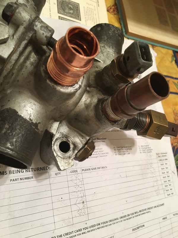
and the new unit fitted with the sensors in place, note that the aux air valve sensor is also in the housing as the head on the carb version does not have a provision for it
796364304_DSCF6624_122_377lo.JPG


The exhaust on the fi models have a cat fitted but here i could only get the standard carb version new, so i drilled the hole in the new exhaust and foun a nut for the O2 sensor to fit, ive ground the nut down and welded it into place, just needs a clean and paint in silver VHT paint
796370407_DSCF6627_122_216lo.JPG


Now the fuel rail has its turn, all old o rings removed and the painful task of getting the old pipes off as the rubber has gone brittle
796379723_DSCF6634_122_135lo.JPG


new rail and injector piles fitted with correct 7.5mm high pressure pipe,note ive added extra length of supply hose as ian not using the inlet fitting, it is going straight to the filter
796381484_DSCF6635_122_752lo.JPG


so now iam at this stage iam looking for the fuel filter bracket and clamp which i belive goes in the coner by the strut area, i have the replacement filter as per spec, i will update the progress.
 
Looks good so far.

So you have the OE cast iron manifold with twin downpipes and the existing EU cam in this unit I presume? Is the ignition by points or the Bosch electronic system?

I see the threaded connector for the inlet fitting, you should be able to just reuse it given you have plenty of fuel hose. There isn’t anything wrong with the approach you are taking as it gets rid of three hose connections and the one threaded compression fitting. Just curious.

Great project. Please keep documenting this as Carl in Virginia has sold his FI setup to someone and they will soon need to follow suit presumably :)

Do you expect more HP or just after better driveability?
 
Coming along!

You could get some of the sleeve heat wrap to protect the fuel hose where it leaves the rail, it would likely increase it's longevity.

I would also wonder about the O2 signal from one bank, but with your setup, it's hard to remedy as you definitely don't want to put the (old style, single wire) O2 too far away from the manifold heat, it would likely not heat to proper operating temp (within a reasonable time) if you put it where the collector is on the carb DP collector.

Do you have any pics of the filter bracket? I don't recall what it looked like. I do have the brackets for the fuel pump, Air flow meter, etc., so I may still have the filter brackets somewhere...
 
My understanding is the narrow band unheated Lambda Sensor measures proportion or percentage of oxygen in the exhaust stream with that of ambient air. The layers of ceramic are coated with a conductive layer that generates a voltage depending on the ratio of oxygen between the two samples irrespective of exhaust volume rate. Like Hussein said, getting the sensor hot enough to work (300C) is the biggy. Also, the sensor is electronically disengaged during idle and WOT. Thats what that rotary switch near the throttle butterfly is for.

The Bosch Automotive Handbook goes into a lot of detail but this link is a good summary:
https://www.gonefcon.com/whatifdyno/theory.htm
 
Last edited:
what a clever idea to get the extra sensors, who was the member here that sold it you, would be interested if they has another modified one
 
A three wire heated oxygen sensor could be placed down at the join of the two exhaust downpipes, this would be a one for one for the single wire. This would get around only looking at the two cylinders versus the average of all four.

Hussein (Lookforjoe) modified his for an alternative engine management system, it is that unit you see being used here. Visiting with a local welder who welds aluminum is what you will need to make your own.
 
having a look at the standard euro exhaust the only place the join of the 2 pipes happen is when it joins to the actual muffler, im not sure would that be suitable for an o2 sensor as that may too big an area to get an accurate reading?


exhaust.JPG
 
I agree with what everybody is saying about the oxygen sensor, it did cause some headaches, so ive decided to go with it and see what happens, i did see this on a mercedes w210 and wondered myself
pic04.jpg


so here is the exhaust all done with sensor in place
upload_2019-2-11_21-47-56.jpeg


now comes the throttle cable and linkage,which i heard can be a nightmare so i had this.
upload_2019-2-11_21-51-23.jpeg


brought this from midwest bayless
upload_2019-2-11_22-5-37.jpeg


note how far out the throttle rod is to the cable control, also note that the aux air valve is monted under th AFM, as the carb head has no mounting point for it, i think its not bad, i dont have the hose clips on yet. The throttle was realy easy TBH, all i did was remove the ball joint lever and turn it around and move the washer over to the inner side
upload_2019-2-11_21-57-33.jpeg

now reversed
upload_2019-2-11_21-58-41.jpeg


the old fuel pump was removed and the push rod removed,the pump refitted with blanking caps fitted so no dirt can ingress
upload_2019-2-11_22-0-58.jpeg


As you can see the engine is running with points at the moment, which i will leave as i know the car was running when i parked it up, i will adjust the timing, and once i know all is well, the ignition will be converted to electronic lumenition, i have the parts ready.

Now connected the fuel lines and fitted the pump in the engine bay,does anybody think this is a good or bad idea for the pump or should i place it under the car as per standard spec?, as iam running a carb tank,the outlet from the tank is at the top,so I thought keep the pump close as possible to the tank outlet, here yous see the pump mounted.
So the outlet comes out of the tank and goes into a glass pre filter,as you can see the fuel and if the filter sock in the tank goes bad the second one should stop any debris going to the pump,BTW the pump sucked up the fuel fine, then it goes into the pump and out to the the big main filter, which i dont have a bracket for it yet, then from the main filter to the fuel rail pipe.
One thing i did note was the pump was very loud on the body of the car, just wondering if i should put it on rubber mounting blocks, havinf said that it only runs when in the start position or the engine is running.
Next will be mounting ECU and wiring the relays...
 
Looks good so far.

So you have the OE cast iron manifold with twin downpipes and the existing EU cam in this unit I presume? Is the ignition by points or the Bosch electronic system?

I see the threaded connector for the inlet fitting, you should be able to just reuse it given you have plenty of fuel hose. There isn’t anything wrong with the approach you are taking as it gets rid of three hose connections and the one threaded compression fitting. Just curious.

Great project. Please keep documenting this as Carl in Virginia has sold his FI setup to someone and they will soon need to follow suit presumably :)

Do you expect more HP or just after better driveability?

Iam looking for better idle and driveability, i dont think the will be any HP gain.
 
Auxiliary air valve needs to be mounted the cylinder head / cam box cover, it relies on being heated to close, where it is I doubt it will ever close.

Fuel pump is usually mounted down low in front of the transmission, not up high where you've put it

SteveC
 
Things appear to be coming along well, nice work. ;)

As Steve said, mount the Aux Air Valve directly onto the engine somewhere; it can be on the block or head or intake manifold, just so the valve assembly gets heated directly from the engine's heat. That keeps it closed after the engine warms up, much like a choke is kept open (AAV functions like a choke, but operates opposite). It does not need to be in a super hot location, often it is somewhere on the intake manifold. I could not tell exactly how you have it, but look into that a little to see if you can get it bolted directly onto the engine.

Bosch fuel pumps are good at drawing fuel up (priming and constant feeding), so you will have no problem with it mounted high. Especially with the fuel tank's supply line being at the top in this case. I'm not sure where the idea these pumps can't "suck" comes from, but it's not true. Insulating it from the body will help quiet it down.

Regarding the O2 sensor location. Many cars of that era had them located in only part of the exhaust system (non-common gas flow area), like you saw on the Mercedes. Honestly I'm not certain what the theory is behind it, but that's how the factory did it on some cars back then. Frankly the O2 sensor does not play that big of a role with this particular type of EFI anyway. So you will be fine where it is.
251_112_Mk1_Downpipe.jpg
 
On with the update, thankyou everyone for the great coments on the coversion, it realy helps and i hope it will help others.
As many of you guys have mentioned that the AAV unit was in the wrong position, so i have moved it, does not seem to be a place to put it, i know it is supposed to sit somewhere down the back of the engine, i have looked for pictures of its proper location and cannot find any reference of it location, maybe someone might have a picture of it and what the braclet should be or where it bolts to. So in the meantime i have bolted it to the end of the head, above the thermostat.
Time to fire up, well at first it was nothing, no fire or cough, so i went through the wiring diagrams and found all electrics were being supplied fine.
upload_2019-2-18_13-56-4.jpeg


The injectors were getting the signals but very weak, so i removed the injector plugs and got a very strong pulse on the injector plugs, so connected one injector at a time, and flashed the points side of the coil, and the injector started clicking(gummed up),so i repeated this for the rest, only no2 injector would not work, so i reconnected them all and the engine started, so i let it run on 3 cylinders for 30mins with an idle of 1000rpm, and then the engine shot up to 2000rpm, no ungummed itself bingo!!! and i have ran the car for 3 days all is fine.
Now the other problem was that the thermotime valve was not letting the cold start injector open, so i measured it with test meter, it was dead
I remembered that there was a thermotime unit in my odds and sods box,ut had been there 24 years, so i have a look and it was the same,so i checked it out it works perfect, just cant remember where it came from.
upload_2019-2-18_14-8-53.jpeg

And the other other problem is the AAV is working, but i could not get the engine RPM to come down from 1300, so i pinched the hose on the AAV and the revs dropped down to 950 rpm, so my AAV unit is leaking air through, does any one have a known good unit?
Also i fitted a better coil, this will be in preperation the the elctronic ignition.
The fuel pump is really noisey as it bolted in the side of the engine compartment, may be thinking on lowering it to the proper place, also looking for a fuel filter bracket and mount, i couldmt find a picture except this
upload_2019-2-18_14-16-57.jpeg


As you can see its in the top left corner, so there more to do yet including ECU mounting and relay and wiring harness. I hope its been helpful so far.more to come.
 
It is embarrassing for me, but I will share some experiences from my 8.5 year old 1300 carb to 1500 FI project on my 78X. I have yet to complete it. Lack of skills, stupidity, laziness, and real life have all contributed to this project languishing in a corner of the garage. Well, two garages since I have moved during this time frame. :(

You can skim thru that thread to see the many things I ran into. I will put a few things here to try to help you finish your project up. You are doing really well and putting me to shame. :D

The fuel filter for FI is mounted high in the left corner. You are pretty close with yours already. Fiat was pretty resourceful in reusing existing mount points. There is a filter mount that re-uses the carb fan studs. I cant find the mount on MWB's site, but you can see it in this picture. It has rubber isolators to hold the filter clamp. I suppose the filter must have been vibrated by the pump and this was the solution.
IM002901.JPG

The ECU goes in the spare tire well. The FI models had a specific spare tire mount to allow for the ECU, so I had to cut out the stock mount on my 78. I figured out where the ECU mount needed to be and added the necessary holes and put nutserts in them. And of course the large hole for the wiring harness to pass thru into the engine bay. Since you have the car running, I guess you already have a plan for this. :) I will post a couple pictures in case you want a reference.
ECU mount 1.JPG ECU mount 2.JPG ECU harness hole 3.JPG ECU harness hole 5.JPG

The fuel pump is mounted down low on the frame for FI. When I was working on this someone ( I will have to look up who) made these pictures for me. Note that when you get your fuel hoses this low, it is a good idea to protect them. There is a stock "splash guard" that has mount points on the bottom of the stock FI pump mount as well as on one fuel tank strap.

Left side alignment.jpg Mounting hole position.jpg Front splash mount.jpg

Here is a picture of the AAV valve. It mounts to the block near the thermostat housing. It uses a couple hex head bolts that fasten into the block. I don't know if a non-FI block will have the threaded holes.
IM002521.JPG

Like I inferred earlier... mine might not be the best example to follow.
 
Last edited:
Now the other problem was that the thermotime valve was not letting the cold start injector open, so i measured it with test meter, it was dead
I remembered that there was a thermotime unit in my odds and sods box,ut had been there 24 years, so i have a look and it was the same,so i checked it out it works perfect, just cant remember where it came from.
View attachment 19619
And the other other problem is the AAV is working, but i could not get the engine RPM to come down from 1300, so i pinched the hose on the AAV and the revs dropped down to 950 rpm, so my AAV unit is leaking air through, does any one have a known good unit?
.

Congrats on getting her running!

That sucks, I'm sorry about the TTV not working. Not sure what happened, the system was functional when I removed it years back :(

The AAV has to be hard mounted to the block or head, or the vibrations will definitely mess it up, and it won't heat fully. You've also confirmed it's getting the continuous switched power I presume? They are also adjustable, but I wouldn't touch that until you have it hard mounted with the plate flush mounted. I'll see if I can find a pic of where it belongs.
 
As Huss says, if the aux air valve (AAV) isn't mounted correctly it won't stay hot enough to keep the idle down when the engine warms up. But the RPM should drop as the valve heats up.

First verify that the AAV is working both hot and cold. The sliding door (internal orifice inside) should move completely from closed to open and back when the valve gets both cold and hot. Start by sticking it in the refrigerator for awhile and observe the size of the opening (looking through the two hose ports). Then add a 12V source to the two electrical contacts and watch as that opening size changes. It should be a rather large difference in size as it heats up. You will also feel the unit get warm once the current passes through it for awhile. As long as you don't get an open circuit between the two electrical contacts on the AAV, it should be working. It's just a heating element inside that moves when an electric current gets it hot. Honestly they rarely fail, but often they need cleaning (see below).

The 'adjustment' (small screw with lock nut on one side) changes the size of the internal opening when it is completely closed. There should still be a tiny opening (see a very small hole through it) even when it is fully closed. But I wouldn't worry about trying to adjust it - that won't make enough difference and the AAV might get messed up in the process.

In addition to verifying that the AAV heats up, it should also be cleaned internally. They get gummed up inside and the sliding door does not move freely. If it isn't moving at all, it could be completely stuck due to internal carbon build up. An ultrasound cleaner works great. Or you can soak it in carb cleaner. It's difficult to get it really clean inside due to the limited access and the fact it will likely be in the 'closed' position. You can manually open the slider (stick a narrow screwdriver through one of the hose ports and push it open) to help clean inside, and to work it back and forth in the process. Getting it clean will make a huge difference in its function.
 
Hi guys thanks for the super information, great pictures JimD thats brilliant, just manged to see the point of the AAV mount now, its on the head
index.php


That now explains why i cannot find the holes, the carb head does not have the flat part on the right, well at least i dont think so, i will check again tomorrow

Hey lookforjoe dont worry about the AAv unit not working, its no biggie, just one of those things, iam still happy to get to this stage, i can confirm its open when its cold, and when i connect it up to 12v it closes down to almost nothing(almost a pinhole in size) in the opening, and tonight the engine started from cold and ran at 1500 RPM, but would not come down after 15 mins unless i crimped the AAV hose, i could be doing somthing wrong, i do still have the air con idle valve, maybe i could use that and experiment and see how that works instead of the AAV unit???.
Cold start valve now working with the new thermotime fitted so thats good .
Thanks JimD thats brilliant for the pictures, so sorry you never got to complete your car, i must say it looks fantastic,very nice, and super info given, if i was over there i would be round yours giving you a hand to help out!!!
I love the furum and all the super guys on here brilliant!!!!
BTW can a video be uploaded onto the forum pages, i never seen any video placed,i would like to show you guys of the running engine.
Again more progress to come.
 
BTW can a video be uploaded onto the forum pages, i never seen any video placed,i would like to show you guys of the running engine.

There is a button that looks like to pieces of film that allows you to insert "Media", but it has to be uploaded to a host first. The text that you see if you click the button says:
You may embed media from the following sites:
I will finish the car someday... I hope. It is my "spare" for now. If I ever destroy the 85, I have a back up. :)
 
Back
Top