1964 fiat 600 (perhaps) cassetta Abarth

oh my god how many beautiful things! Thank you for your suggestion!
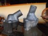
Today the last pieces of the engine arrived, so we started the assembly.
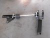
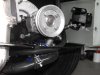
As you can imagine, when welding a metal, the parts are deformed; now, when they welded the base, the wall tilted slightly inward, about a little less than a cent. To recover and make the crankshaft stops well match, it flattened by about 2 hundredths of a mm. This leads to no longer having the tension already on the distribution chain. The piece we were waiting for was the chain tensioner that was mounted on the Fiat 900 fire engines.

IMG_20200430_141009_1.jpg
IMG_20200430_141017_7.jpg


The only modification needed is a small milling of the internal edge of the timing cover.
IMG_20200430_141055_8.jpg
IMG_20200430_150802_8.jpg
 
@myredracer : Exactly! We have a fiat 600 aluminium cover.
Although tonight we will stop to sleep in the rest area in the workshop, I will only be able to take more photos in the morning, at this moment we are a little tired ...
Good night to all!
 
Last edited:
That is a cool little part, interesting that you could get it to fit an 850/1050 engine. Was it ever actually fit to this type of engine or is the bearing cap bolt distance the same across the small displacement FIRE and the 850/1050 series engines?

The bracket looks like a standard part (the black strap across the bearing cap).

Nice modification to get to a solution.
 
Basically the base is the same. The caps sizes are the same. It is a good solution for repair cases like mine.
The piece is absolutely the standard chain tensioner mounted on FIRE engines.
I'm sure standard on the 903 cc, type fiat 127 or Cinquecento. The subsequent 1000cc type series had the timing belt on the right side with overhead camshaft.
 
A Little ot.
This morning, workshop,the last pieces of the modifications made to the 600 by my father-in-law many years ago ...maybe in some time we could make an engine with those pieces.
IMG_20200502_082447_8.jpg
IMG_20200502_082435_8.jpg
IMG_20200502_082618_4.jpg
IMG_20200502_082516_4.jpg
IMG_20200502_082652_6.jpg
IMG_20200502_082636_0.jpg
 

Attachments

  • IMG_20200502_082833_2.jpg
    IMG_20200502_082833_2.jpg
    122 KB · Views: 114
Cool old parts. Several years ago when my father passed away I had the task of clearing out his lifelong collection of automotive stuff. In the back of my mind I was thinking I'd discover lots of very cool items like this. Unfortunately there were only a couple of interesting things, and nothing of any real use. But I'll keep them as mementos to display on a shelf some day.
 
Goodmorning everyone! Today we continued the assembly of the engine
The crankshaft pulley has been graduated at 5 ° at a time to help us get a little more precise phasing.
IMG_20200504_115816_4.jpg

Then we mounted the thermostat. As you may have noticed, the upper part was cut from the base and then welded in another position; in doing so we managed to mount it on the head without beating against the bulkhead and eliminate the original one on the radiator.
IMG_20200504_115829_5.jpg
IMG_20200504_115855_9.jpg
IMG_20200504_115848_9.jpg
 
:):):):):):) thank you!:):):):):)

We mounted the flywheel and crossbar. Since the engine vibrations would have created cracks on the crossbar support, in addition to the abarth reinforcement I also added the transverse reinforcements that go to unload on the bumper studs.
IMG_20200504_182032_6.jpg
IMG_20200504_181959_4.jpg
IMG_20200504_182024_0.jpg
IMG_20200504_182014_3.jpg


Perhaps they are a little rough, but with the crossbar mounted they blend in quite well and are functional.
Tomorrow we'll try to finish the work...
:D
 
Looking good. Interesting what you did with the thermostat housing. I did a similar thing to get the hose to line up to the top of the radiator. In my case, I have an Abarth 750 radiator that is taller than stock. The 45 degree hose I used has a different diameter at each end and it was tricky to get the angle on the housing correct.

With the extra power you will have, I would suggest considering an anti-torque bar/rod setup to reduce the amount the engine wants to twist when you hit the throttle. I made a bracket to attach to the water pump and modified the bumper mounting bracket. I used a standard vibration isolator (available in many sizes) and used what is often called a "turnbuckle" to be able to adjust the length of the rod by twisting it. There are other ways of doing this and Abarth did it on the later 1000 TCR cars.
 

Attachments

  • DSCF1275.JPG
    DSCF1275.JPG
    233.7 KB · Views: 133
  • DSCF1370.JPG
    DSCF1370.JPG
    266.8 KB · Views: 145
  • DSCF1376.JPG
    DSCF1376.JPG
    272.7 KB · Views: 140
uh! a great idea to mount it this way. I am building what goes from the gearbox to the chassis and I am studying for that of the engine, but as you have done it is a very valid solution in my opinion. I remember those mounted on the TCRs, they had the body riddled with rivets to hold the frame support bracket in place.

ABA 2574 engine strut.jpg

I've Just a pair of these vibration isolators in workshop.

congratulations on the thermostat welding!
 
I was trying to find that photo this morning! To do that you would the late style 1000 TCR oil sump. If you are using a rear radiator, it could be a challenge to find room for the strut rod. In my case, besides not having the TCR oil sump, I didn't have space with the hoses in the way. The "belly pan" I have drops down at an angle because my radiator also hangs down lower.
DSCF1326.JPG


I also did this setup to limit fore/aft movement.


DSCF1319.JPG
 
Just a thought to keep in mind. Those vibration isolators are made by vulcanizing the two end metal plates onto the rubber middle part. I've noticed that after a couple years in a hot engine bay the rubber hardens, and under the constant loading/unloading there is a tendency for the end plates to separate from the rubber (failure of the vulcanized joint). I use them to mount intercoolers, oil coolers, radiators, etc, so that's where I've noticed this problem. Your application has even greater loads. Therefore you might consider replacing them every couple years or possibly look for a more robust substitute. But then again it might not be an issue for your clever use of them. ;)
 
The isolators are available in a few different types of "rubber" - natural rubber, polyurethane, silicone and neoprene. I have no idea if one is a better choice for auto use. Besides more dampening, I got larger dia. and longest length with the idea that they'd last longer, but I dunno. Lifespan = whenever they don't seem to work anymore. :)
 
available in a few different types of "rubber" - natural rubber, polyurethane, silicone and neoprene
I didn't realize there were so many different types. The ones I've been using are plain rubber I think. Some of the other materials should last longer. But I just wanted to mention it so that you can keep an eye on it. I'd hate to see it fail and cause something to happen as a result.
 
the main problem I think is to choose one with the right hardness. The ones I have in the workshop are used for compressions (like engine mounts), therefore too hard, so I would transfer too many vibrations to the body and block too much the lateral movements of the engine.
A middle ground would be needed, today I am looking for something else and an effective solution.
 
Just a thought to keep in mind. Those vibration isolators are made by vulcanizing the two end metal plates onto the rubber middle part. I've noticed that after a couple years in a hot engine bay the rubber hardens, and under the constant loading/unloading there is a tendency for the end plates to separate from the rubber (failure of the vulcanized joint). I use them to mount intercoolers, oil coolers, radiators, etc, so that's where I've noticed this problem. Your application has even greater loads. Therefore you might consider replacing them every couple years or possibly look for a more robust substitute. But then again it might not be an issue for your clever use of them. ;)

Hi Jeff,
In the late 1960's GM came out with a new motor mount exactly as you describe. I bought a 1968 Nova (Chevy 2) with a 307 V-8 and two speed powerglide transmission. Hardly a racer. In downtown Los Angeles I had to cross a wide street and merge with traffic in the #1 lane. I floored it with all 170 or so horsepower. The mount separated allowing one side of the motor to lift enough to JAM THE THROTTLE FULL ON! With the reflexes of youth I turned the motor off and back on while the steering locked (to prevent theft they say) and unlocked. When taken to the dealership their rep asked what type of abuse I subjected the car to. Several weeks later General Motors recalled several MILLION cars to be "improved."
 
In the late 1960's GM came out with a new motor mount exactly as you describe.
The smaller ones that I use to mount components are very basic ones from a industrial supplier, so not really designed for heavy loads - and for that matter they are inexpensive and may not be of great quality. The one in Frank's 60's GM car may have been a older technology of rubber or construction, that likely has improved since then. So the larger, more modern type that @myredracer uses could very well be fine. Especially if the material is one of the better choices than the simple rubber used in mine.

But @Frank L. Di Gioia has bright an idea to mind. There are many different styles, sizes, and types of mounts made to support engines, transmissions, etc, available for various production vehicles. They were designed for this application and therefore might be much better suited, and more reliable over time. One thought off the top of my head is the engine mounts used on classic Fiat 124's. Who knows these might even be something a company like Abarth would have used for such a purpose back in the day. While this particular example may not be the best choice for the intended use here, it could offer some thoughts for other ideas. I'm referring to these (early and late types):
enginemountb1.jpg
s-l300.jpg
 
Back
Top