
Rupunzell
Bernice Loui
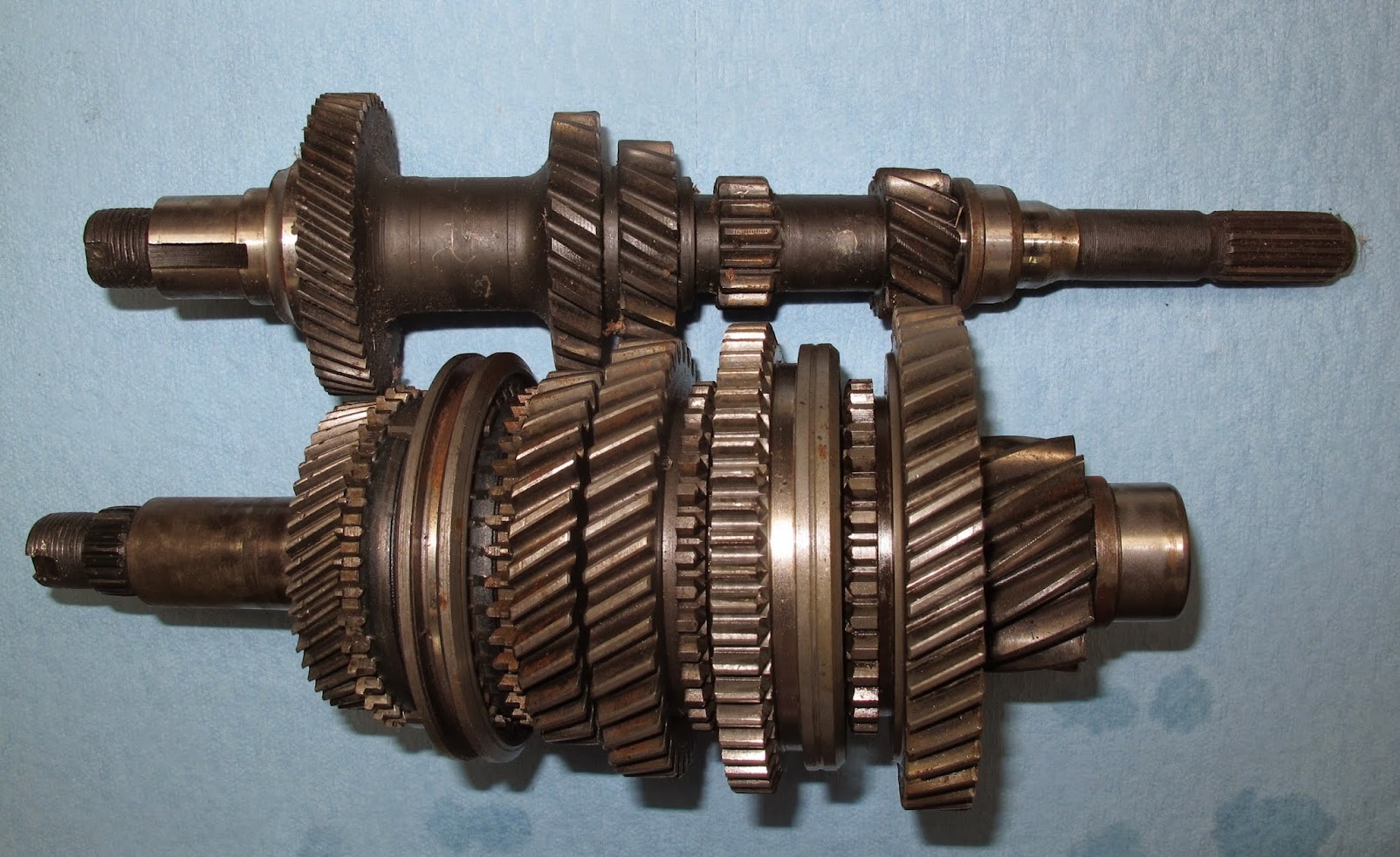
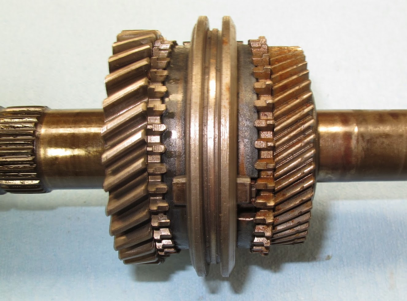
The input gear set and Pinion gear set from a 1979 transaxle.
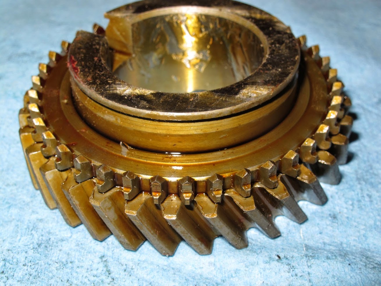
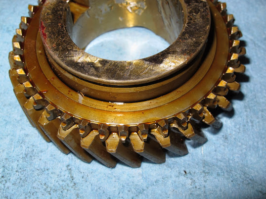
The reverse gear on the input gear set. This often gets chipped, worn and abused as previous owners and abuser crash the shifter into reverse gear. If this gear is excessively chipped or damaged, the entire input gear set will need to be replaced.

Gears, bearings, sliders and related removed from the final drive pinion gear spread out on the bench.
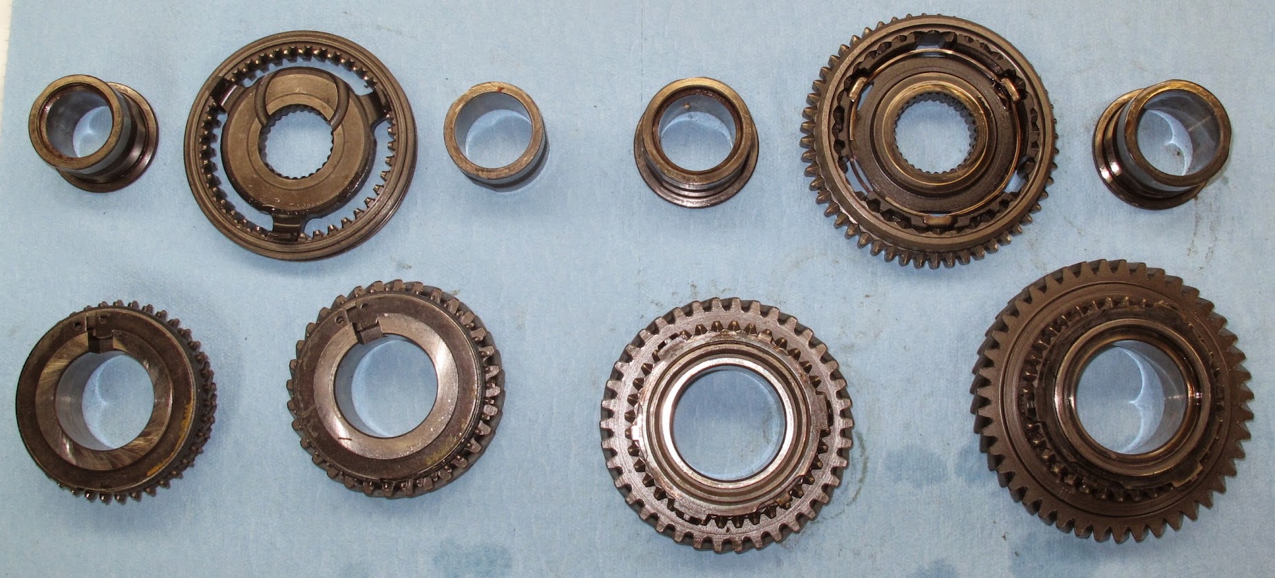
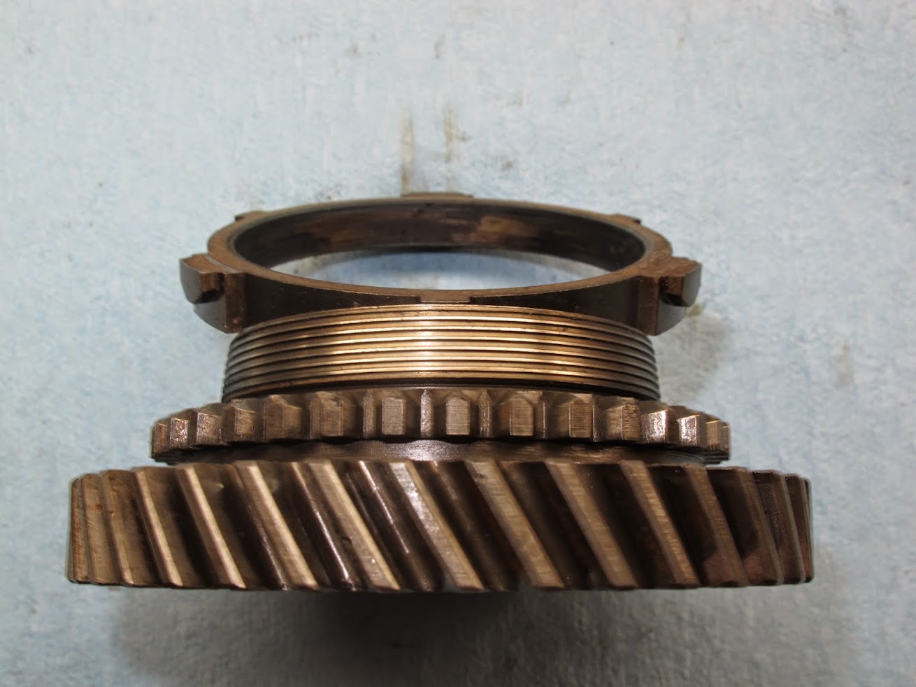
3rd & 4th gear with slider:
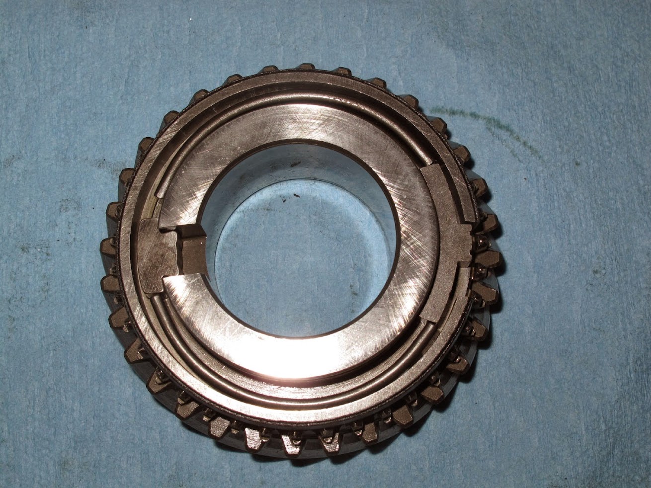
1st & 2nd gear with slider:

1st or 2nd gear with bearing removed, only significant difference is the OD of the gear and number of gear teeth.
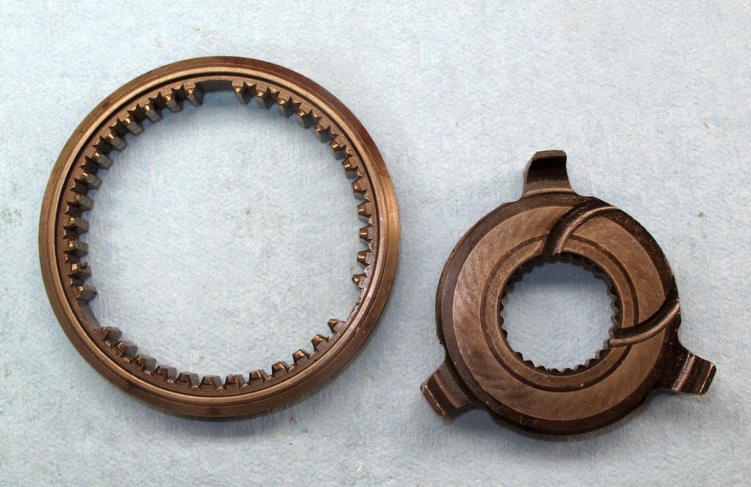
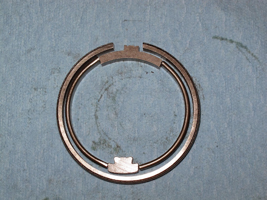
1st or 2nd gear syncro ring. This is Fiat's variation of the Borg Warner syncro introduced in 1967. Basically the Borg Warner syncro design (circa 1930's) inverted. For those who are curious about this syncro design, here is a link for more info.
http://books.google.com/books?id=af...=onepage&q=fiat inverted cone synchro&f=false
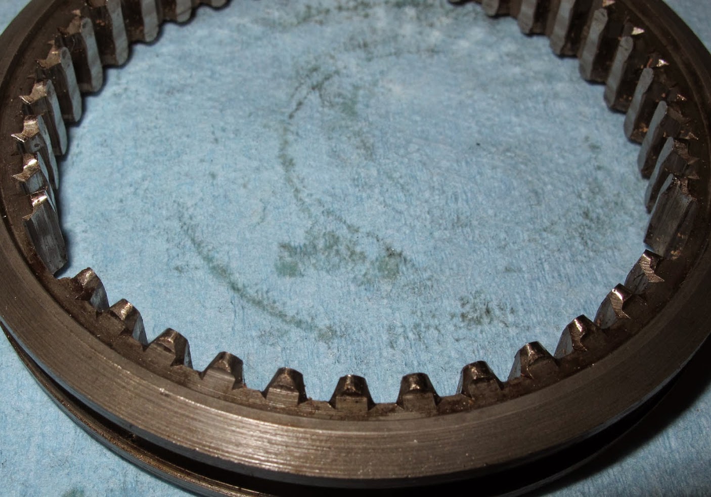
Check the gap between the syncro ring bottom edge -vs- bottom of the cone on the gear. If the gap is too small, the syncro ring or cone on the gear is worn. These syncros are pretty durable and rugged. If there is wear, it is often a worn syncro ring. Note the condition of the engagement teeth points. They should look like this one, the tips should be pointy and well defined with little to no rounded tips.

Syncro ring removed exposing the cone on the gear;
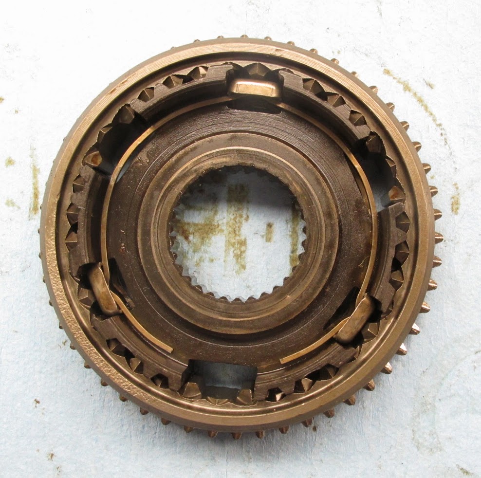
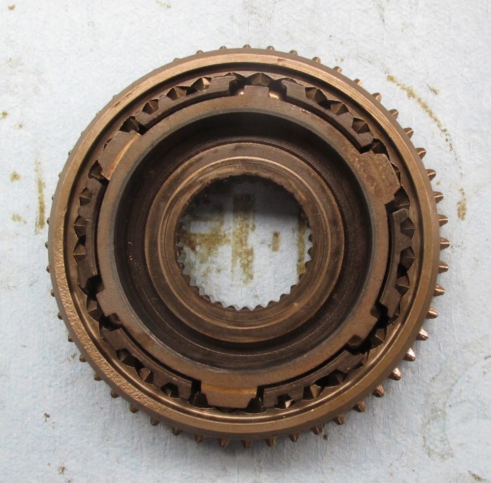
1st, 2nd, reverse hub & slider assembly.
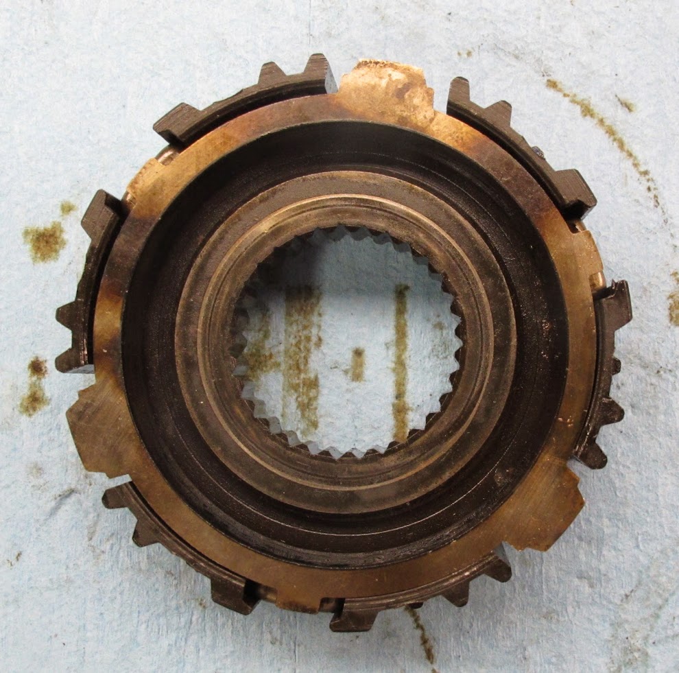
1st, 2nd, reverse slider with the hub removed.

1st, 2nd Hub apart. This illustrated the hub, detents and the spring one both sides of the hub. The circular springs have a bump that fits into each detent. Check these parts for wear. They are usually OK unless the gear box was abused.

This is how the syncro ring must fit into the hub. Note the tab orientation relative to the hub. If this is installed wrong, the slider will not move.
When installing the hub into the slider, note these notches in the hub relative to the detents. These must be properly oriented or the hub and slider will not fit together.
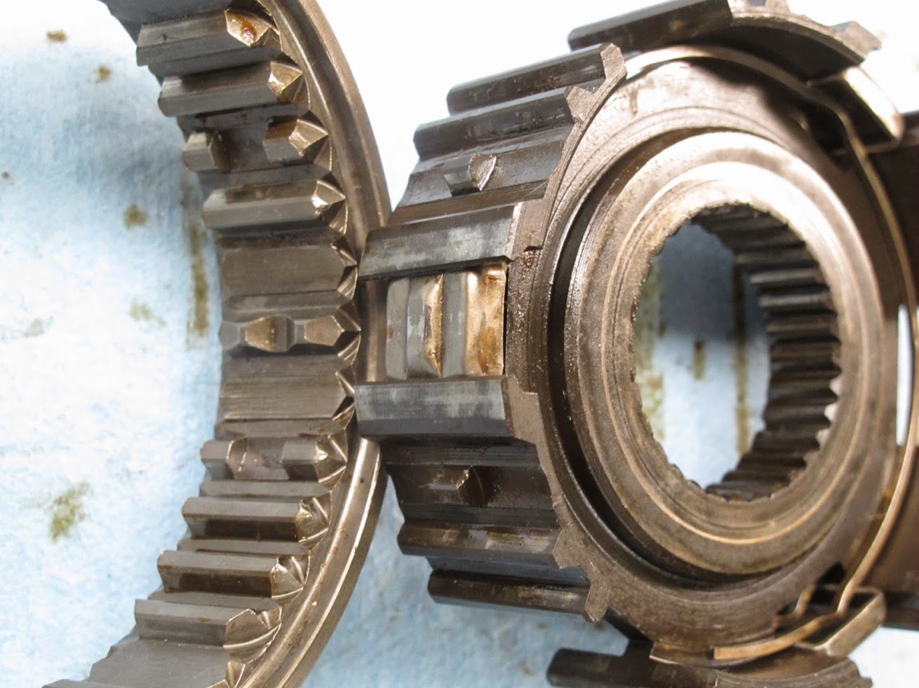
Hub, detents, slider assembled. Make sure the slider is oriented properly or reverse gear will not engage. The straight cut gear teeth on the slide should line up with the straight cut reverse gears on the input gear set when they are nested together. If they are not line up, the slider is backwards.

Syncro ring installed. Do this prior to placing the assembled unit on to the 1st gear as this will help to prevent getting the syncro rings in the wrong position. Once the hub/slider assembly is installed onto the 1st gear, place 2nd gear on top making it into a 1st-2nd gear unit.
3rd & 4th gear hub and slider. 5th gear is near identical.
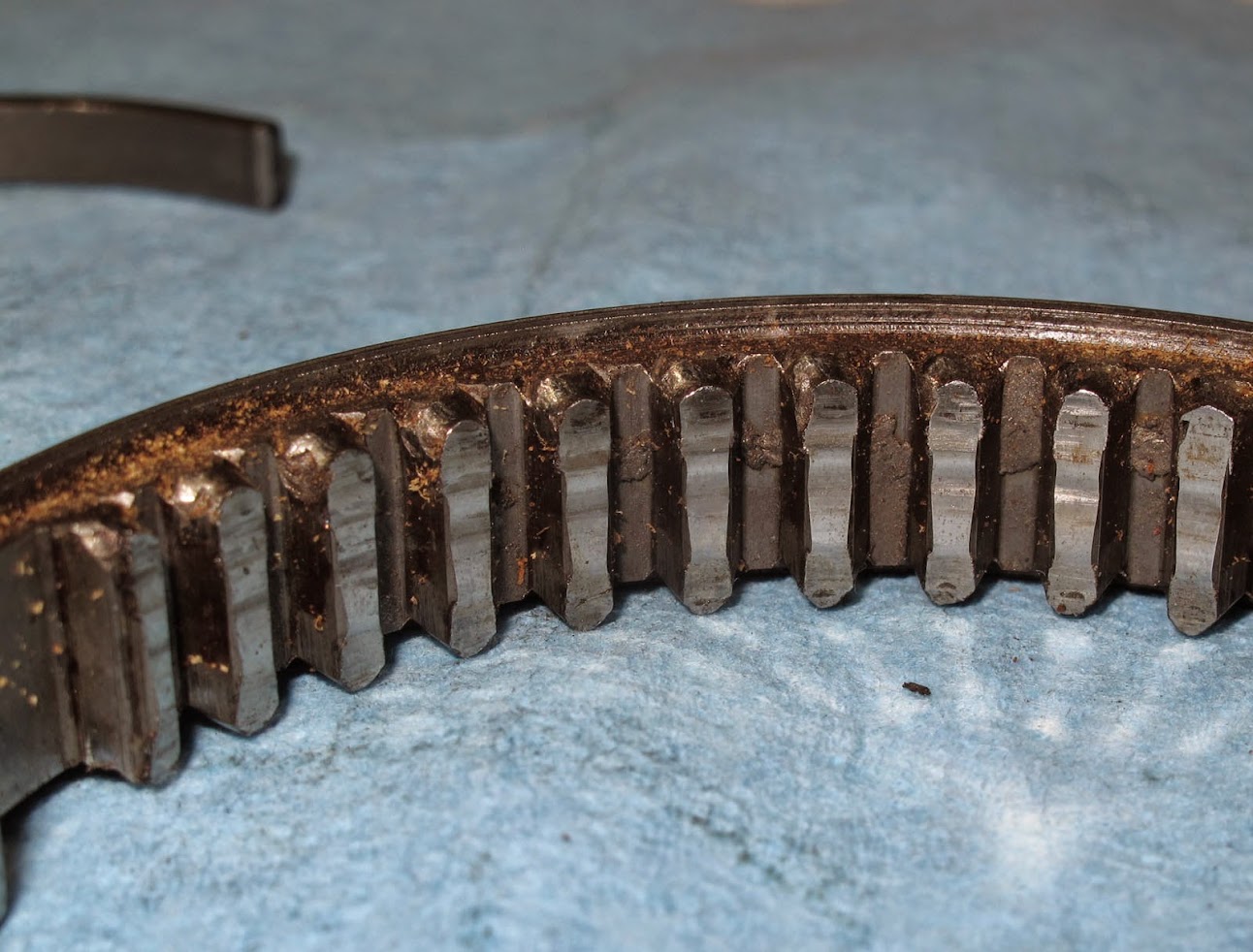
3rd/4th slider is the most bashed part in this gear box next to reverse gear. The damage is caused by using a LOT of force on the gear lever in an attempt to get the gears to shift faster. No force on earth will result in Porsche/servo band syncros to engage or shift to the next gear faster. They require a finite amount of time to work and more force will not alter this fact and reality. This is what happens to the slider teeth as they are abused. When new, these slider teeth are pointy, well defined and not rounded at all.
A closer look:
Keep this in mind shifting into 3rd, 4th and 5th gears.
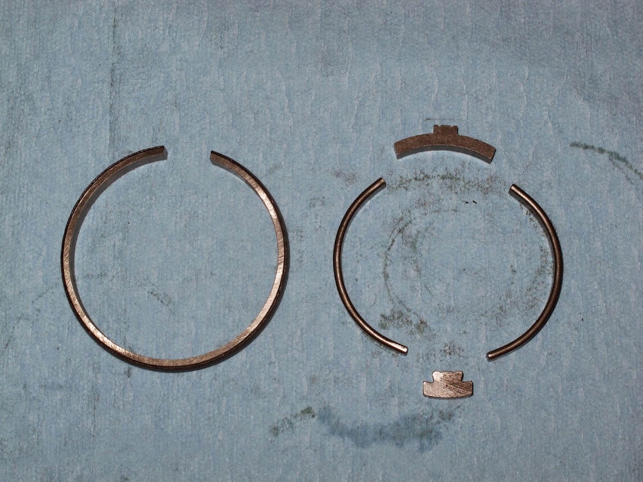
3rd, 4th and 5th gears have Porsche or Servo band syncros. These were introduced by Porsche to the world during 1953 in the Porsche 356. Since then Porsche or servo band syncros have been used in everything from Alfa Romeo to Ferrari to Porsche. All share the inherent problems with these Porsche syncros. Some where in the Mid-late 1980's Porsche stopped using this syncro design. This is the innards with the large snap ring removed.
These are the internal components of the Porsche syncro, Outer band, braking rings, stop blocks.
Exploded view:
Worn -vs- new outer syncro band. The band on the bottom has a polished and well worn surface, one on the top is new which is rough and textured. This textured surface generated the friction required against the slider to work the braking bands inside the syncro. Together they work to match the speed of the gears for the shift. Some folks flip the outer bands over to used the lesser worn surface against the slider. Sort of works, but not really. When one is this far into a gear box, worn parts like this should be replaced.

These are the braking bands inside the outer syncro band. This aid the outer band's grip on the slider. They do wear and should be replaced when they begin to look like these. There are impression marks from force applied to the tiny grooves inside the outer syncro band. Indication of the forces involved with how this syncro operates.

Notice how walloped the engagement teeth are on this 3rd gear from not waiting for the syncros to work and applying plenty of force trying to get 3rd to engage faster. Once this damage is done, it all goes down hill pretty fast. Changing or using different oil will not alter the fact these parts are damaged and will no longer shift properly.
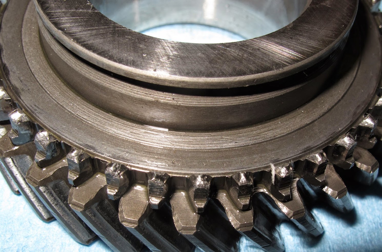
This is what a new third gear looks like;
A closer look. Notice the shape and condition of the engagement teeth which is what they should look like on the gear and slider.
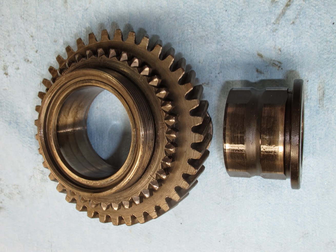
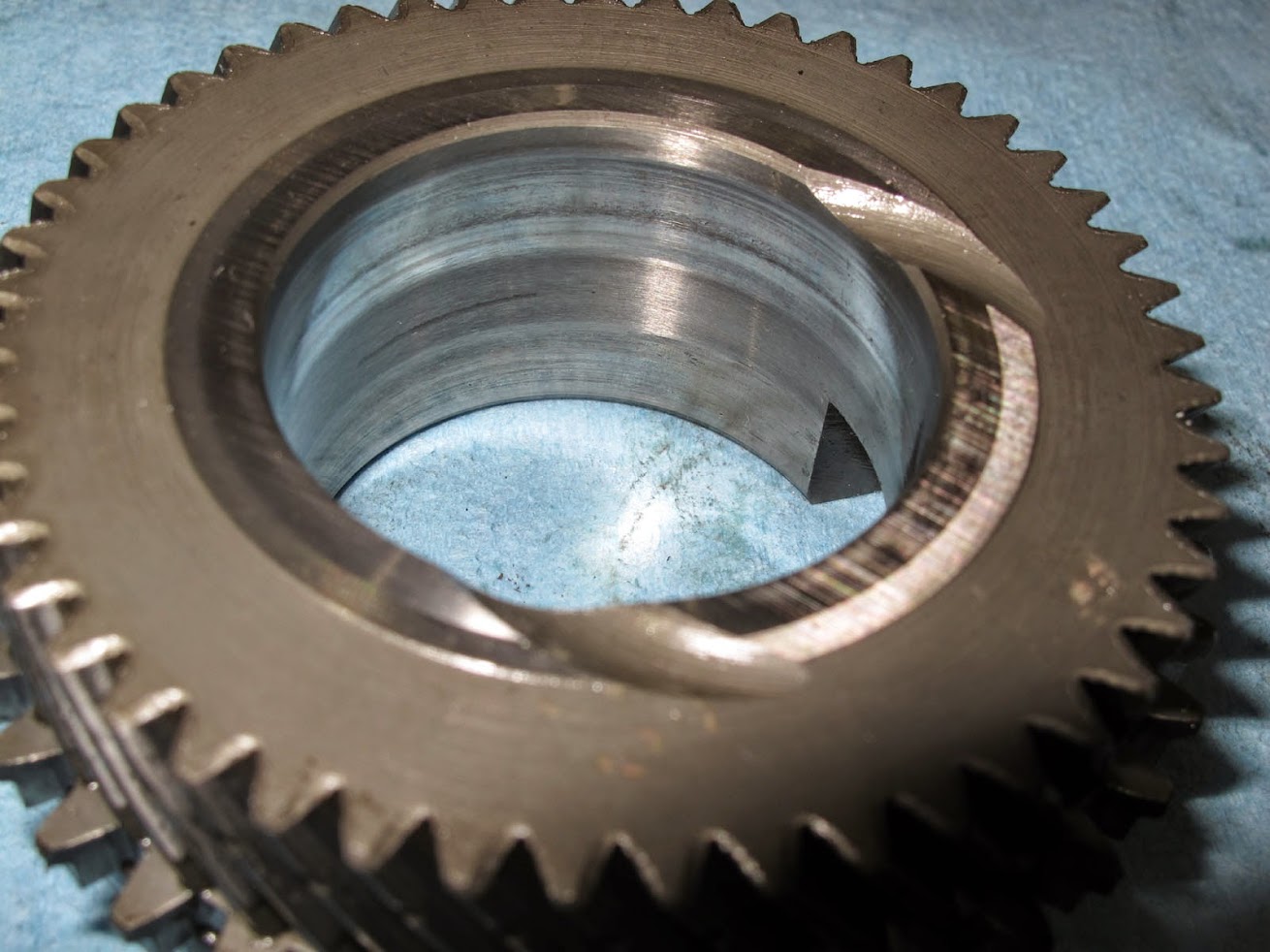
This image of the gear bore is for the GL-1 users, note the wear an scoring on the inside bearing surface of the gear.
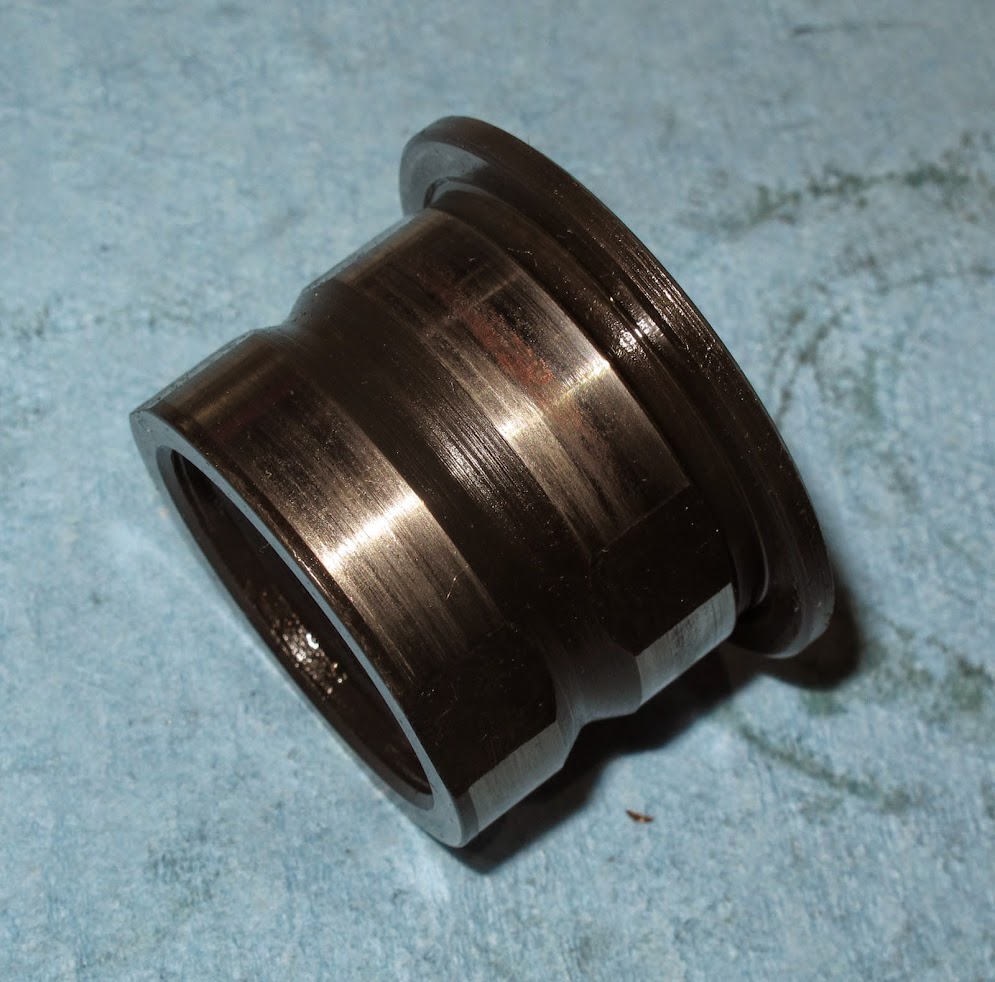
Here is the sleeve bearing that lived in that gear, it is cooked. While GL-1 was the spec Fiat gear lube, there are much better gear box oils to use today. This why few can convince me using GL-1 in these gear boxes is actually a good thing today.
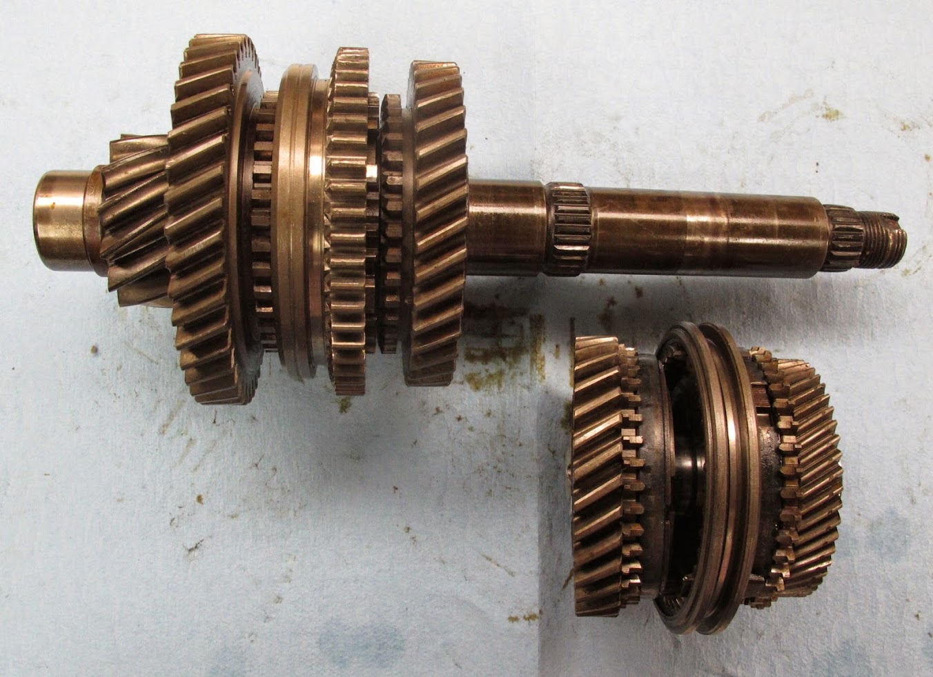
Stack 3rd & 4th back together with the slider and put it on the final drive pinion gear after 1st and 2nd gear stack is on the final drive pinion gear.
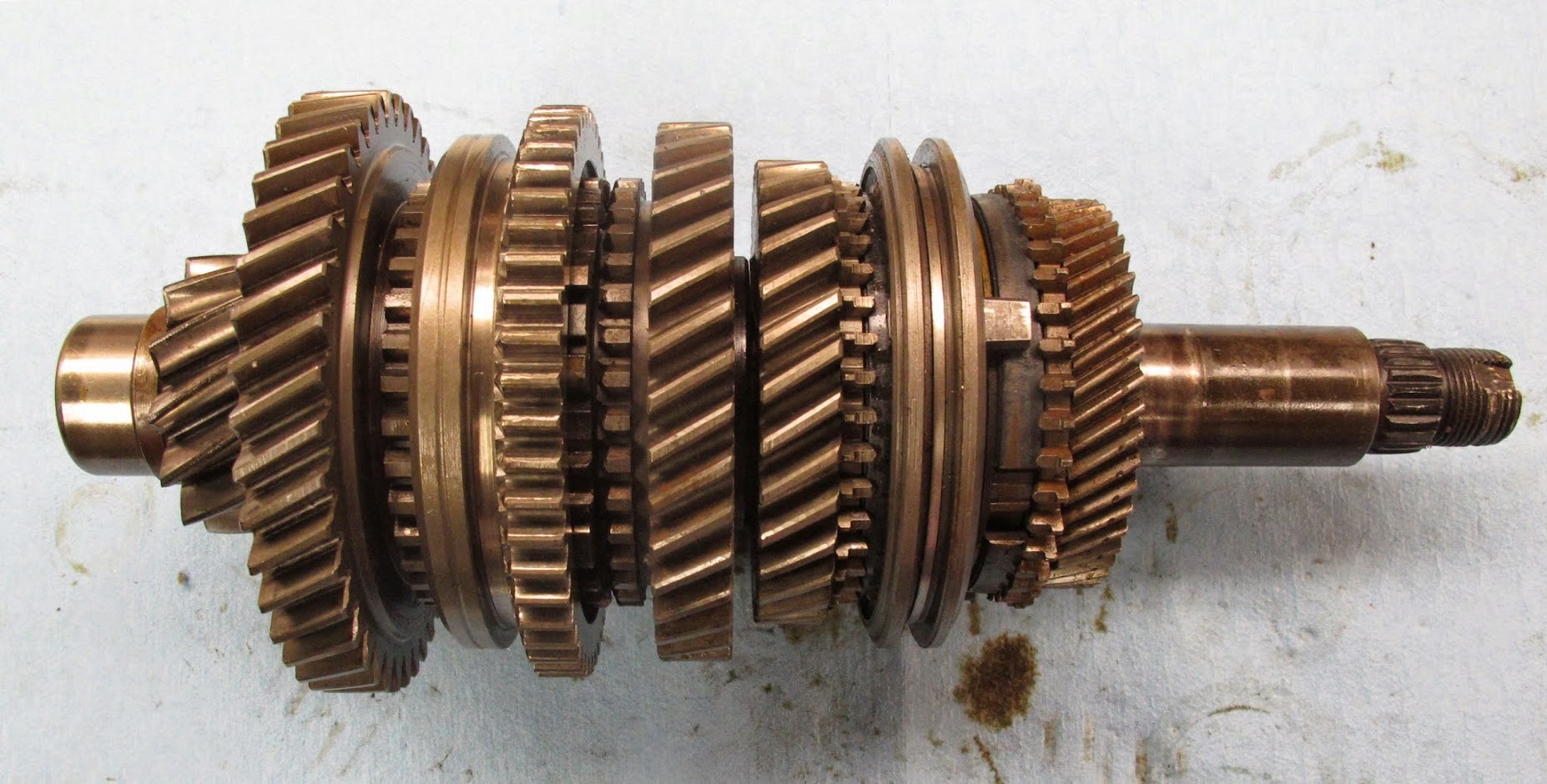
Pinion gear stack done.
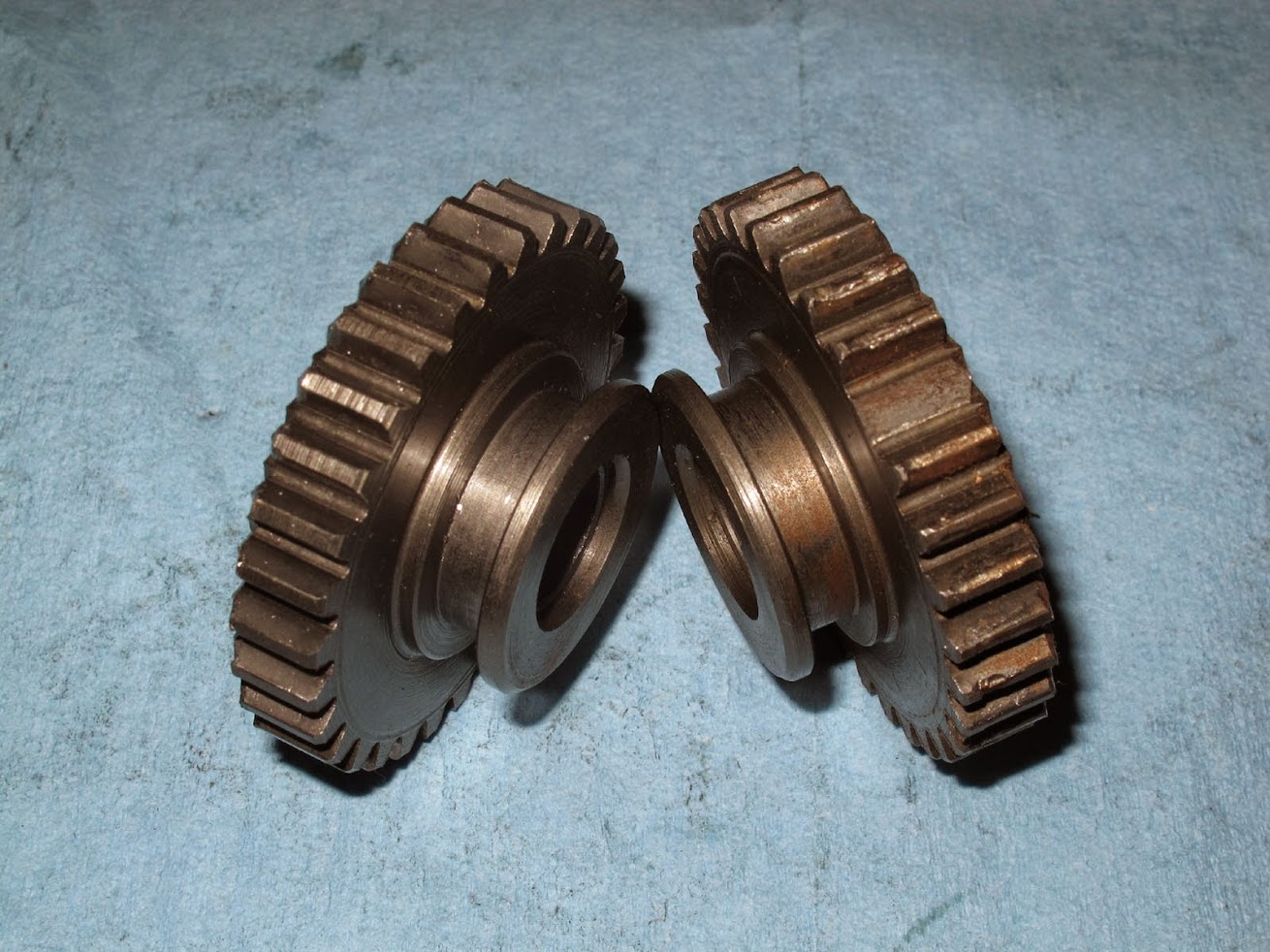
This for those who enjoy slamming this gear box into reverse. Missing gear teeth often results from doing that.
Next up, assembly.
Bernice
The reverse gear on the input gear set. This often gets chipped, worn and abused as previous owners and abuser crash the shifter into reverse gear. If this gear is excessively chipped or damaged, the entire input gear set will need to be replaced.
Gears, bearings, sliders and related removed from the final drive pinion gear spread out on the bench.
3rd & 4th gear with slider:
1st & 2nd gear with slider:
1st or 2nd gear with bearing removed, only significant difference is the OD of the gear and number of gear teeth.
1st or 2nd gear syncro ring. This is Fiat's variation of the Borg Warner syncro introduced in 1967. Basically the Borg Warner syncro design (circa 1930's) inverted. For those who are curious about this syncro design, here is a link for more info.
http://books.google.com/books?id=af...=onepage&q=fiat inverted cone synchro&f=false
Check the gap between the syncro ring bottom edge -vs- bottom of the cone on the gear. If the gap is too small, the syncro ring or cone on the gear is worn. These syncros are pretty durable and rugged. If there is wear, it is often a worn syncro ring. Note the condition of the engagement teeth points. They should look like this one, the tips should be pointy and well defined with little to no rounded tips.
Syncro ring removed exposing the cone on the gear;
1st, 2nd, reverse hub & slider assembly.
1st, 2nd, reverse slider with the hub removed.
1st, 2nd Hub apart. This illustrated the hub, detents and the spring one both sides of the hub. The circular springs have a bump that fits into each detent. Check these parts for wear. They are usually OK unless the gear box was abused.
This is how the syncro ring must fit into the hub. Note the tab orientation relative to the hub. If this is installed wrong, the slider will not move.
When installing the hub into the slider, note these notches in the hub relative to the detents. These must be properly oriented or the hub and slider will not fit together.
Hub, detents, slider assembled. Make sure the slider is oriented properly or reverse gear will not engage. The straight cut gear teeth on the slide should line up with the straight cut reverse gears on the input gear set when they are nested together. If they are not line up, the slider is backwards.
Syncro ring installed. Do this prior to placing the assembled unit on to the 1st gear as this will help to prevent getting the syncro rings in the wrong position. Once the hub/slider assembly is installed onto the 1st gear, place 2nd gear on top making it into a 1st-2nd gear unit.
3rd & 4th gear hub and slider. 5th gear is near identical.
3rd/4th slider is the most bashed part in this gear box next to reverse gear. The damage is caused by using a LOT of force on the gear lever in an attempt to get the gears to shift faster. No force on earth will result in Porsche/servo band syncros to engage or shift to the next gear faster. They require a finite amount of time to work and more force will not alter this fact and reality. This is what happens to the slider teeth as they are abused. When new, these slider teeth are pointy, well defined and not rounded at all.
A closer look:
Keep this in mind shifting into 3rd, 4th and 5th gears.
3rd, 4th and 5th gears have Porsche or Servo band syncros. These were introduced by Porsche to the world during 1953 in the Porsche 356. Since then Porsche or servo band syncros have been used in everything from Alfa Romeo to Ferrari to Porsche. All share the inherent problems with these Porsche syncros. Some where in the Mid-late 1980's Porsche stopped using this syncro design. This is the innards with the large snap ring removed.
These are the internal components of the Porsche syncro, Outer band, braking rings, stop blocks.
Exploded view:
Worn -vs- new outer syncro band. The band on the bottom has a polished and well worn surface, one on the top is new which is rough and textured. This textured surface generated the friction required against the slider to work the braking bands inside the syncro. Together they work to match the speed of the gears for the shift. Some folks flip the outer bands over to used the lesser worn surface against the slider. Sort of works, but not really. When one is this far into a gear box, worn parts like this should be replaced.
These are the braking bands inside the outer syncro band. This aid the outer band's grip on the slider. They do wear and should be replaced when they begin to look like these. There are impression marks from force applied to the tiny grooves inside the outer syncro band. Indication of the forces involved with how this syncro operates.
Notice how walloped the engagement teeth are on this 3rd gear from not waiting for the syncros to work and applying plenty of force trying to get 3rd to engage faster. Once this damage is done, it all goes down hill pretty fast. Changing or using different oil will not alter the fact these parts are damaged and will no longer shift properly.
This is what a new third gear looks like;
A closer look. Notice the shape and condition of the engagement teeth which is what they should look like on the gear and slider.
This image of the gear bore is for the GL-1 users, note the wear an scoring on the inside bearing surface of the gear.
Here is the sleeve bearing that lived in that gear, it is cooked. While GL-1 was the spec Fiat gear lube, there are much better gear box oils to use today. This why few can convince me using GL-1 in these gear boxes is actually a good thing today.
Stack 3rd & 4th back together with the slider and put it on the final drive pinion gear after 1st and 2nd gear stack is on the final drive pinion gear.
Pinion gear stack done.
This for those who enjoy slamming this gear box into reverse. Missing gear teeth often results from doing that.
Next up, assembly.
Bernice
")
 , off was easy.