500 Abarth 1.4 Turbo swap.

I was referencing Ricar’s post not the one in this build which is unequivacably the MultiAir.

Ricar stated his was a ‘08 which would not be a MultiAir.

However as he has clarified his 08 motor is a Honda Fit L15 type motor which is another matter entirely.
OH I didn't even consider Ricar was talking about a non FIRE swap.

Nevermind. Confusion resolved.
 
I too think that the “bench test” isn’t going to give a real world scenario.
I agree. A heat gun does not push much air compared to a real life scenario, but the air from a heat gun is MUCH hotter. There is also a follow up video with a real life test.
I am charging 1.6 bar on my setup and I could see intake temps in the 50-60⁰C area with 20⁰C ambient with the barrel. Intake temp was reduced to 35⁰C by replacing the IC at the same ambient temp, so the style (and size) of the IC has a big impact. It also seems like the barrel type IC is more restrictive to airflow. I've set the ECU to start the circulation pump at 30⁰ to "accumulate" cold water and to avoid heat soaking the system. I've never heard about using the AC pump for IC cooling before. I am curious about the result and will follow with interest.
 
Regarding stand alone ECU, I've been in contact with MaxxECU. There is no direct support for Multi Air but there's a good chance that the MaxxECU Race unit can handle this engine with its flexible and advanced CAN bus functions. They think the market is small, and making tests for an official solution would be too time consuming and costly.
I agree in general. With the vast availability and capability of aftermarket standalone systems right now I'd be shocked if none could control the multiair. It might take some serious tuning hours, but should be possible. Are there no race teams running these engines?
 
More progress. A “box” is hammer formed to hold all modules etc for this swap. Much care and skill from Mr. Tony K. To make this piece look like it was made for this car.
D7F31D9C-3CFA-4A3B-8680-27488D945A08.jpeg
F698903F-FEE4-43BF-A131-822C713C495E.jpeg
D7F31D9C-3CFA-4A3B-8680-27488D945A08.jpeg
F698903F-FEE4-43BF-A131-822C713C495E.jpeg
03EF96FE-2E52-44BD-BACC-49DFA959051A.jpeg
72228BA5-14E8-4BE8-8386-97C683CC2F5E.jpeg
678C8FAF-5191-4AF0-BC9D-62328F7F22D9.jpeg
4F12B057-8FED-4ADE-BD18-17D8E462B08C.jpeg
F1293E51-63E9-4C4D-A43F-A0E7BDD32B4F.jpeg
F9C89812-6FD5-46B7-8D53-EFEE5168539B.jpeg
80FA306E-0659-4832-B0E6-A65FB8004834.jpeg
 
A little bit about the drive line. First the splines on the Fiat 500 Abarth transmission to the half shafts to the X1/9 are the same. The Abarth transmission is 3/4" wider on the right side of the car and the half shaft needs to be shortened. The half shaft on the left side of the car is 3/16" too short and needs a 1/4" spacer installed between the spline hub and CV joint at the transmission side. The right side CV joint spline adapter needs to be custom made for the right side as it presents 3 problems. The stock spline adapter is too short and will only engage the transmission spline by 1/4" and the boss on the shaft for the transmission seal is not located in the correct place for the seal to work and transmission fluid will leak out. The last issue is that the CIR clip used on the X1/9 transmission is not used on the Abarth transmission on the right side but needs to be ground into the splined receiver on the right hand side. The solution is to make a custom adapter that uses a section of the Right hand side CV shaft from the stock Abarth car. Because the Abarth is front wheel drive to prevent torque steer the length of the CV shafts must be equal and to do this Fiat uses a pillow block mounted on the engine block with a sold section of drive shaft between the transmission and the pillow block. Because the pillow block bearing is also a thrust bearing a cir clip is not used on the right hand splines of the transmission to keep the half shaft from sliding out of the transmission. The half shafts on the Abarth are smaller in diameter than that of the Fiat X1/9 and are case hardened. The stock Fiat X1/9 half shafts are larger and made from mild steel.

IMG_4460.JPG


This is a completed adapter that was used on my car and Bob Martin's car. The lower adapter section is made from the slug of 304 Stainless Steel and machined to the following specs. The price for the slug of Stainless was aboutm$50 CND the same 2" x4" section since covid went to $127CND. VW makes flanges that are forged and splined which could be an alternative but I have not tried them on this application. I have seen it done on another car with a bigger engine than the Abarth. That could be a time saver in machining as stainless steel is difficult to machine. I currently have 5000 miles on my car and no issues with the drive line.

IMG_4463.JPG


This is what the right side half shaft looks like from the Abarth car.
DSC01833.JPG

Just under 4" of the shaft is used in making the adapter.

DSC01834.JPG


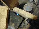
An angle grinder with at .045" cut off wheel is used to cut through the case hardened portion of the drive shaft while it is spun on the lathe.
At this point the softer center can be now cut with a power hack saw. The case hardened shaft will not allow a cut to be made and a file skates off of the hardened case of the shaft.

DSC01835.JPG


In the first two adapters made the stub shaft where it is pressed into the hub of the adapter is machined on the lathe with a tool post grinder and the hub is machined with a .005" interference fit and pressed with about 20 tones of force. In an effort to get around this machining issue with using a grinder the shaft end was stacked in fire bricks and heated for 20 minutes with a propane torch then closed in for 1 hour to draw back the temper of the case of the shaft. The result was that a file can now cut the steel and I will be able to machine it on the lathe with carbide tools.
DSC01842.JPG


Since a lot of hogging needs to be done on the stainless steel slug I made up a tool that uses inserts that were given to me years ago. Indexable tools are nice by very expensive so often old broke carbide inserts are silver soldered to tool steel to make up custom tools.

DSC01839.JPG


DSC01840.JPG


More on this part as time permits.

TonyK.

Grimsby Ontario Canada.
 

Attachments

  • DSC01836.JPG
    DSC01836.JPG
    246.9 KB · Views: 72
I had a little time over the last few days and here are progress pictures.

With the back side of the hub machined I removed the slug and installed the 3 jaw chuck to hold the stub shaft. I was able to turn it with carbide tooling and centre drilled it. Once assembled the centre hole will be used to skim a bit of material off of the face of the flange to true it after pressing and welding.
IMG_0330.JPG

IMG_0331.JPG


The stub shaft is set aside and now the 4 Jaw is put back on the lathe and a dial gauge was used to centre the slug. The machining on this side of the adapter now starts.
IMG_0332.JPG


The adapter is now drilled and boring will be finished once this face has the flange surface machined and cupped out for the CV joint to mate to it.
IMG_0336.JPG

Here is a shot of the Abarth right side transmission and engine drive line.
IMG_4393.JPG


TonyK.

Grimsby Ontario Canada.
 
Last edited:
Hi Tony, I'm new to the forum. I own a 1978 1300, that has been in storage the last 20 odd years. I recently stumbled across a 2002 Stilo with a Pratola Serra 1.8 16v and C510 gearbox that I try to swap in my X1/9. Would you know if I have to adjust the clutch master (travel) to work with the hydraulic clutch release bearing? (looks the same as 500 C510 gearbox of your Abarth swaps)
Not used to post on forums, so if there are better ways of asking, please say so.

Best regards,
Marc
 
I have the stock Fiat X1/9 master cylinder connected to the Fiat 500 hydraulic actuated throw out bearing. The issue is to connect from the X1/9 hose to the new 500 hose. I had to make an adapter. It all works fine.

TonyK

At Bob Martins with Jim Decker in Radcliff Kentucky.
 
Great, have fun at FFO 2022!

For the hose connection, I plan to connect the 1/4 rigid line of the X1/9 to the (6mm) rigid end of the Stilo clutch hose with a 2 x M12x1 1/4 inch brakeline coupler and some freshly made flares on either side.
 
This is great reading, thanks for taking the time out to do it. Now reading through this, If I was to get a T-Jet abarth engine, I could run this with my aftermarket ECU (its a Motec)?
I do have a 16v turbo coupe engine I was looking to instal into the X, but this unit looks more compact and I suspect less work where the chassis leg has to be modified to provide clearance for the nose of the gearbox? T-Jets Abarth engines are £5-600 and plentyful. Its really got me thinking about going down this route
Hi, my apologies for hijacking this thread, but do you know if the I4 2l 16v turbo of the Coupé is a Pratola Serra (or B-) engine?
If so I assume it has similar if not the same outer dimensions as the 1.8 16v I am currently swapping from a Stilo. That fits with relatively little modifications to the X. Obviously you'll probably need to review turbo placement and intercooling (similar to @TonyK's Multiair Abarth swaps), things I don't have to deal with.

Best regards, Marc
 
In the past week or so I have had a bit of time to work on the shaft adapter. First I needed to hollow out the body of the adapter so that the CV joint can operate without binding. Once done the adapter is turned 180 degrees in the 4 Jaw chuck and centred so that the hole can be bored. A boring tool is used to open the hole to -.005" undersize for an interference fit. The shaft is now press fit into the flange. I greased the bore and shaft and it still required about 8 tons of force to press the shaft into the adapter. Once done 2 1/4" holes are bored on the mating line and pins will be driven into the holes and the TIG Welded. Three 5 gallon buckets of chips/turnings were made to machine this adapter.
IMG_0667.JPG
IMG_0668.JPG
IMG_0669.JPG
IMG_0671.JPG
IMG_0671.JPG
IMG_0673.JPG
IMG_0674.JPG
IMG_0670.JPG
IMG_0672.JPG
 
Well for those that are following this post you may be wondering why is this taking so long. Well the reason is there are other things that get in the way of efforts on this project. First off I am doing a constitutional challenge regarding rights to trees and that take time and a whole lot of money. Next my 2014 Dodge Ram 2500 with 6.7 cummins does not have any heat in the cab. Problem the small tubes on the heater core are plugged and the dash needs to be removed to change the heater core. I also installed today a small mesh filter to prevent the heat exchanger from clogging up with debris and hoping that the heater core will not need changing for years to come.

Then my son wants an outdoor fire place with a smoke house built and I need to make the Stainless Steel door frames and doors for the burner chamber and the smoking chamber. I also had a tree to cut down and split for fire wood. Then pick up 100 4"blocks for the fire place.

And so that the heater core does not get plugged up again I ordered an inline filter to prevent that from happening which needed to be installed.

Now back to the shaft adapter. I turned tapered steel plugs and drove them into the bores on the shaft and adapter line. Then TIG welded at 95 amps to make sure they would stay in place. Chucking the adapter in the lathe with a live centre showed a run out of .15" So, all faces were trued in the lathe. The out side diameter was .018" under sized so shimms were intalled so that the CV joint and the adapter can be put inline so that the mounting bolt holes can be drilled and tapped.

TonyK.

Grimsby Ontario Canada.

IMG_0676.JPG
IMG_0678.JPG
IMG_0680.JPG
IMG_0688.JPG
IMG_0694.JPG
IMG_0695.JPG
IMG_0696.JPG
IMG_0697.JPG
IMG_0699.JPG
 
Well the reason is there are other things that get in the way of efforts on this project.
The real issue is that you are just too damn capable Tony. No one would ever ask me to work on any of those projects. I would be of little use and mostly in the way. Unless there is a flashlight that needs to be held. :)
 
Next time somebody wants to complain about working on an X heater box, just take a look at the Ram 2500 above and thank your lucky stars......
 
Back
Top