TonyK
True Classic
Thanks for the replies.
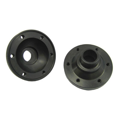
Just when I thought everything was going well with the adapter the CV joint wrenched and my centres were all off. I had no choice but to start the drilling and tapping again of the mating flange. A new pilot drill guide was turned in the lathe and as I drilled the first hole I tapped it and put a bolt in it to keep the two parts together and prevent the turning of the two parts. With that done now with some extra holes ( sorry Mike) last operation was to machine in the cir clip groove. I set up the lathe on slow rotation and used a cutting wheel on my battery angle grinder to cut the groove then used my dremel with some small cut off wheels to dress the groove. Part done. Next is to cut the axle, weld it and check to see if it is straight.
TonyK.
Grimsby Ontario Canada.