Matt Zerega
Passion, not Practicality.
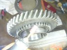
Greetings Gents. I've found surprisingly little information out there about working on the 850 gearbox...so I figured I'd share a bit of experience. Overall, I'm pleased with the elegantly simple assembly; it was simple to take apart with basic tools. So far, there's only one exception: removing the bolts that tie the ring gear to the carrier - there isn't enough room between the carrier bearings and the bolt heads to fit a socket, so I had to use a crow-foot wrench on the end of an extension attached to an impact wrench. It was a bit awkward, but it worked. Aside of that, the most difficult, unpleasant part was scraping and cleaning 53 years of crust, dry grease and dirt off every surface and out of every crevice on the case. It took a few hours and a whole lot of "solvent" (gasoline) to get the case clean.
Why I'm doing this: swapping out the 8/39 gearing with a 9/35 set I bought from Middle Barton Garage in the UK, will yield 70 MPH at 3,600 RPM (with the 195/50 16 tires I'm running on the rear of my Spider). With the stock gearing and tires, the motor needs to spin at 4,850 RPM for the car to reach 70 MPH. Fine for a stock motor at freeway speeds in 1969, perhaps. I'm building a 954cc turbo motor that I expect will almost double the factory 52 HP, so the taller gearing will be a worthwhile change, especially considering the speeds most people drive on California freeways.

Once the case was reasonably clean, here's how I took it apart:


I'll share more as I get farther along.
Why I'm doing this: swapping out the 8/39 gearing with a 9/35 set I bought from Middle Barton Garage in the UK, will yield 70 MPH at 3,600 RPM (with the 195/50 16 tires I'm running on the rear of my Spider). With the stock gearing and tires, the motor needs to spin at 4,850 RPM for the car to reach 70 MPH. Fine for a stock motor at freeway speeds in 1969, perhaps. I'm building a 954cc turbo motor that I expect will almost double the factory 52 HP, so the taller gearing will be a worthwhile change, especially considering the speeds most people drive on California freeways.
Once the case was reasonably clean, here's how I took it apart:
- Pull out the little pin that’s visible once the side cover is removed. The pin holds the reverse idler gear shaft in place. Pull the pin and then tap out the shaft from inside the bell housing.
- Engage both of the gears by pushing them towards the ends of the case until they snap into place against the adjacent gears. This locks the whole assembly into place and prevents it from turning when you spin the pinion nut off (in a later step).
- Remove the spring clip that holds the big nut fastened to end of the pinion shaft, and remove the big nut. Note that the retainer fits through a hole in the side of the nut, and into one of the pinion-shaft splines. You'll need to remember this when you reassemble the gearbox.
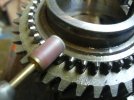
- Measure the pinion depth from the machined carrier-cap face (Thanks, JohnT
") . When I measured, I got 1.936” with my depth micrometer. You'll need this reference when install the new pinion. A variety of shims - of varying thicknesses - are available (not sure where, yet) to adjust the pinion height. The shim(s) are installed between the pinion and the bearing that seats in the bell housing.
. When I measured, I got 1.936” with my depth micrometer. You'll need this reference when install the new pinion. A variety of shims - of varying thicknesses - are available (not sure where, yet) to adjust the pinion height. The shim(s) are installed between the pinion and the bearing that seats in the bell housing.
- Once the retainer is removed from the nut, remove the big nut off the end of the pinion shaft using an impact driver.
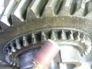
- Remove the three 13mm bolts along with their tabbed washers (visible in the photo showing measurement of pinion depth), that hold the pinion bearing in its bore.
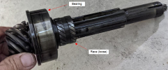
- Now, gently tap the pinion shaft out through the bell housing. It’ll come out along with with the bearing that’s installed up against the pinion’s gear teeth, and the race that's installed just behind it. The race slides right off.
- All of the gears installed onto the pinion shaft are now loose; remove them from the case and clean ‘em up.
I'll share more as I get farther along.
Attachments
Last edited: