903cc main bearing oil-hole orientation...?

Matt Zerega

Passion, not Practicality.
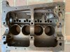
Good evening rear-engine Fiat motor aficionados.... I have a question for those with experience building the bottom end of 903cc variants. The motor I've got has "100GBC" cast into the side of the block, and a 4-bolt water pump.

I'm beginning to learn that these old Fiat motors aren't broadly supported in the aftermarket...which makes it difficult to find correct parts, and accurate, confident advice. I'm inquiring with you-all (passionate enthusiasts) to address the second part...

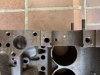
Enough background; here's the issue: I ordered a set of NOS Glacier standard main bearings. They do fit the saddles but the orientation of the oil holes - between the bearing and engine block - look funky...especially on the front main; one of the oil holes in the engine block is completely obstructed and the other is ~80% obstructed. This doesn't seem right at all.
FrontMain.jpg


On the center main, the bearing's oil holes are offset about 15mm relative to the engine block's oil holes. I'm not so concerned about the center bearing since oil will flow freely through the groove in the block (behind the bearing shell) and out the two holes in the bearing. Good enough, I think.......
CenterMain.jpg


Shall I simply drill the front bearing in alignment with the block's oil holes....or....should I find some other brand/part number?

Any advice from an experienced Fiat 100-series engine builder would certainly be appreciated.
 
Hi Matt,
As a general suggestion don't modify your 903 block as the next set of bearings might have another location still yet! For the best solution do wait for one of the vendors with expertise suggest a solution. I'd lean toward getting the proper fitting shell. Good luck as I'm awaiting a call from my shop with similar issues.
 
Thanks, Frank. I would not propose modifying the block, given the ease with which the bearing shells can be modified. Save for any additional reliable information, I'll go ahead and drill the shell to fully expose the block's oil holes.
 
Hi Matt,

This is how I understand the stock 850 engine flow.
The 850 engine oil flow is from the pump tube into front main cap. The sealing rings (if in good shape) on the crankshaft move oil forward inside the pulley and with centrifugal force clean the oil and it enters the crankshaft front end hole. Inside crankshaft is pressured at the bearing surfaces rod and mains. Then from the main bearing into the block via the larger holes in your pictures pressures the camshaft bearings. (On the engines I have the front main smaller hole should be covered because that returns to oil sump. Some engines have a narrow bearing shell to expose the hole?) The front cam bushing leaks oil to lube the oil pump drive gear and front chain. After the cam bearings oil moves into galley cast in the side of the block equalizes the pressure and is checked by the gauge. The center cam bearing top hole is for oil flow to the cylinder head rocker stand and into rocker shaft for the rocker arms. Then oil returns thru the pushrod holes and lubes the cam lifters.

There are many ways to improve the oil system. Changing flow direction, remote oil filter, oil jet to oil pump gear, etc.
Those mods change the block and there is no return to stock spec.

Good luck,
Kent
 
Thanks, Kent. Your info, in conjunction with the factory oil flow diagram, is helpful.

After reading various posts on the subject, I'm most of the way through modifying this block for "full flow" oil system that passes all oil through an external cartridge oil filter before returning the clean oil through the boss where the factory pressure sender resides. I've plugged the factory drain-back hole adjacent to the factory pressure relief valve (with a 1/8 NPT plug) and fabricated a front main-cap block-off plate. I plugged the nose of the crank as well (1/8 NPT plug). A Seat 133 oil pump is on its way from Europe (this pump - with its integral pressure relief valve, which clears the factory 850 Spider aluminum oil pan).

Apparently, the smaller of the two holes on the front main - on this block - is a simple, straight through-hole that catches un-pressurized oil flying around inside the crankcase i.e., it's not connected to any part of the pressurized oil passageway that I can see. This tiny through-hole simply leaks a tiny bit of oil onto the "sealing rings." I went ahead and relieved the bearing shell to expose this tiny hole since the sealing ring assembly will remain despite the "full flow" modification. I also enlarged the bearing shell's hole that sits on top of the hole leading from the front main to the front cam bearing i.e., the larger of the two holes.

Anyway...the attached photo shows what I've done, for better or worse. Proof will be in the pudding. If anybody knows - through direct experience - that this is a bad idea, by all means, do let me know....soon :)

FrontMainBeforeAndAfter.jpg

Passages.jpg
 
Last edited:
My memory is foggy on this and don't want to say the wrong thing. You want the grooved bearing and I believe you just need to drill a hole in the bearing cap to line up with the hole in the block so that oil comes up from the main oil gallery basically like you've done. By memory, the hole should be 3/16" dia. You can find detailed info. on Mahlon Craft's website, on Paul Heyden's writeup on building a race motor and in Greg Schmidt's Fiat and Abarth tricks book. You can also find some various good info. on the Guy Moerenhout forum if you going looking through the various posts there.

If doing the remote oil filter mod, rather than relocating the pressure relief valve onto the 850 oil pump, I'd definitely use an A112 pump which already has the valve mounted right on it or the Seat pump if it's the same thing. I've got an A112 pump in my highly modified 903 motor which was built by Paul Heyden. If doing the "reverse oil flow, pressurized center main bearing" mod, as Gregg Schmidt put it, you'l be able to get rid of those "miserable oil delivery sealing rings". With no need for the centrifugal filter, you could use an early 600 pulley or an aftermarket small dia. one. I'm pretty sure I have a spare 600 one and I also have a nice steel small dia. one (but not sure if I should keep or not). My motor has a Scuderia Topolino alloy small dia. pulley.
 
Last edited:
Thanks, Frank, Kent and Gil. With your info, a bunch more reading and a whole of careful inspection of that parts I have.... here's what I observe, and believe thus far. A little affirmation and/or correction would be great :)

As per Fiat design, all the pressurized oil enters here, via the tube bolted to the oil pump (assuming, of course, the pressure relief valve isn't open). The sealing rings direct the pressurized oil forward, to flats on the crankshaft nose.
OilEnters.jpg

The oil finds its way to the passage in the nose of crankshaft via the flats machined onto crankshaft snout.
SealingRings.jpg

And here's the speculative part for which I need affirmation: the tiny hole in the front-main journal -- behind the rear sealing ring -- simply provides a path back to the crankcase for any oil that manages to move backward. This feature seems unnecessary to me - I don't really appreciate why it's there - but I will not claim to be anywhere near an automotive power plant engineer. What purpose does this tiny hole really serve?

In other words, in a "reverse flow", externally filtered oil system conversion, exposing this tiny passage is entirely unnecessary since the initial flow of pressurized oil will no longer be provided via the main cap. Also, the actual sealing rings can be discarded and the spacers onto which they mount must be retained.
TinyReliefPassage.jpg

(picture above - showing where the front main will get its oil, following the "reverse flow" oil system modification. The two forward-facing yellow arrows show where pressurized oil would flow prior to the modification)
OilPath.jpg
 
Last edited:
I'm going to keep my mouth closed for now as my short block is at the shop and hopefully being finished. Best bet is to get a copy of the reverse flow oiling system as described by Greg Schmidt, John Edwards or Paul Vanderhayden. It's pretty simple and actually very clear as they explain it but you don't want to get it wrong.
 
Thanks again, Gents. I've read all the Schmidt, Heyden and Faza stuff on oil system modifications, and none of it says anything about the tiny hole in the front main journal that connects to the crankcase. I cannot fathom why its there...but I'm paranoid about covering it with the bearing, so I cut a small relief in the shell.

Schmidt eloquently says, "A new crankshaft pulley and plugged crank snout does away with...those miserable oil-delivery sealing rings...". Taken in combination with a visual assessment (looking at the layout of all the parts), Schmidt's comment is enough for me; I'll get rid of the rings and retain the spacers.

If anyone knows what the tiny hole's intended purpose actually is, please do tell.

ixnayIloIngRay.jpg

P.S. Jeff's right. This block already has an oil-feed passage for the center main bearing, leading to/from the main oil gallery - put there by Mirafiori Works.
 
Last edited:
I am guessing the hole is there to provide oil onto the sealing rings and not needed if you remove the rings. I think the hole just gets left as is and I can't see a mention in any of the articles of closing it off.

I just thought of another thing since you have it all apart. You can drill a hole in the cam bearing that will supply oil onto the distributor/cam gear. Very easy to do and worthwhile. Abarth had a gear oiler using a banjo fitting and small dia. pipe to do it. Paul Heyden describes how to drill the hole in his article.
 
Here’s a picture of a 202b block with the stock oiling system showing a plug in that hole. I have another 202b block with the exact same plug from Abarth. We were not sure why they did this but since both blocks had the same mod we left it alone. This probably just adds to the confusion but since the subject was brought up...
 

Attachments

  • 002D8717-871D-4B46-9DB8-1190B344C204.jpeg
    002D8717-871D-4B46-9DB8-1190B344C204.jpeg
    129.9 KB · Views: 142
  • A0C61BF5-75AA-416F-88BC-3C1F8DAB3464.jpeg
    A0C61BF5-75AA-416F-88BC-3C1F8DAB3464.jpeg
    108.1 KB · Views: 220
Is "venting" a main bearing shell directly to the non pressurized crankcase going to cause a loss of pressure at that bearing?
 
I had a look at a 903 block in my garage today. It doesn't have that small hole. Not sure what that means? Did Fiat add it on the late 903 blocks?
 
Thanks to t38bob I'm convinced, now. The tiny relief I added to the front main bearing - to expose the tiny hole leading to the crankcase - is unnecessary. And in response to Gene, it's clear that pressurized oil between the front crank pin and the bearing shell - along the internal circumference at the width of the tiny relief (~1.5mm) - is exposed to the low pressure crankcase via the hole. So, yes, a tiny amount of oil supplied to the crank pin will find it's way back to the crankcase. But I say, "insignificant." Since that 1.5mm relief area is only at the very edge of the 20mm-wide bearing shell, I'm not going to sweat it; the rest of the interface area between the crank pin and bearing will remain pressurized.

The tiny hole in the block sits precisely at the edge of the bearing shell, at a point that used to 'see' whatever oil that got past the rear sealing ring (my speculation earlier in this thread appears to be incorrect). After the "reverse flow" system conversion (look carefully at the third picture, in post #7 in this thread) there will be no oil between the two sealing rings anymore. Post conversion, pressurized oil at the front main will now originate from the front cam bearing area, not the main cap (which facilitates getting rid of the sealing rings). And remember, pressurized oil is vented along the entire outer edge of both sides of the bearing shell anyway. If I were more of a purist, I'd put a new, unmodified front-main bearing shell in there before buttoning this thing up....but I'm not.

Thanks to everyone for helping noodle through this. I really appreciate having other enthusiast's info and guidance.
 
Last edited:
Back
Top