Alternative Brake Master Cylinders -Using Stock Location

In this post
Ahhh. I confess I haven't been keeping up with that thread, so I missed that. Someday I will go through the whole thing. Right now is my narrow window of decent weather here and I have a million outdoor jobs to get done in a very short period. Unfortunately most of those jobs are property maintenance items, so I'm not getting nearly enough done on my car projects. Perhaps I need to spend even less time on here. :(
 
Huss, not sure if it will help any but there are some really affordable items like balance bars and related brake components available from China. Perhaps search one of the online retail sites and see what comes up. There might be something already made that is affordable enough to start with. Here is just an example:
https://www.aliexpress.com/item/328...1.0&pvid=0515422b-6eb1-4b3b-998b-49f9f75547a1

Thanks Jeff. I've already bought the Wilwood parts off Amazon - I was able to get a few of them discounted for 'open package/repackaged" state. I don't care, I'm not saving the packaging :D
 
This is where i'm at:

Tried the CompBrake mockup box

IMG-20200129-151017.jpg


I don't know how much height clearance there is above the pedal box - however this would need a few inches of clearance to work.

IMG-20200129-164554.jpg


IMG-20200129-164551.jpg


Decided I'll be much happier with a setup that with less complexity, so I'm going ahead with building the bias bar off the pedal arm pivot. Have to figure out how to box out the mounting plate I need to make to prevent flex under braking

IMG-20200129-194846.jpg


IMG-20200129-171325.jpg


IMG-20200129-171601.jpg


this will be welded here, with that offset I only need to widen the entire assembly by an inch

IMG-20200129-173948.jpg


IMG-20200129-172436.jpg


IMG-20200129-172212.jpg


IMG-20200129-172427.jpg


IMG-20200129-172442.jpg
 
Looking good.

Perhaps stating the obvious, but drilling a clearance hole into the side of the box here (arrow) may allow the assembly to move closer to the box a bit. Otherwise it will allow the adjuster's threaded-rod more movement without hitting the box.

IMG-20200129-172442.jpg
 
Went back & forth with Bernice on the FB xWeb page regarding the pedal pivot, involving "double shear" and other terminology I don't normally work with :D. She pointed out that the sleeve needed to be centered according to the original clevis pin center line, I had to offset about 9mm in the wrong direction .

IMG-20200130-111551.jpg


So I welded the sleeve so that the centerline is as described.

EDIT - had to revise the weld on this later, the way I have it here the return spring had no way to seat
IMG-20200130-174916.jpg


IMG-20200130-174904.jpg


made a template for the MC mounting - has to be modified to actually work

IMG-20200130-080327.jpg


IMG-20200130-174534.jpg


IMG-20200130-174537.jpg


notched the pedal box to allow the setup to be as close to the side as it can, based on the required sleeve positioning.

IMG-20200130-175940.jpg


Have to build the brackets out once I figure out the MC mount end

IMG-20200130-180036.jpg


IMG-20200130-180041.jpg
 
Last edited:
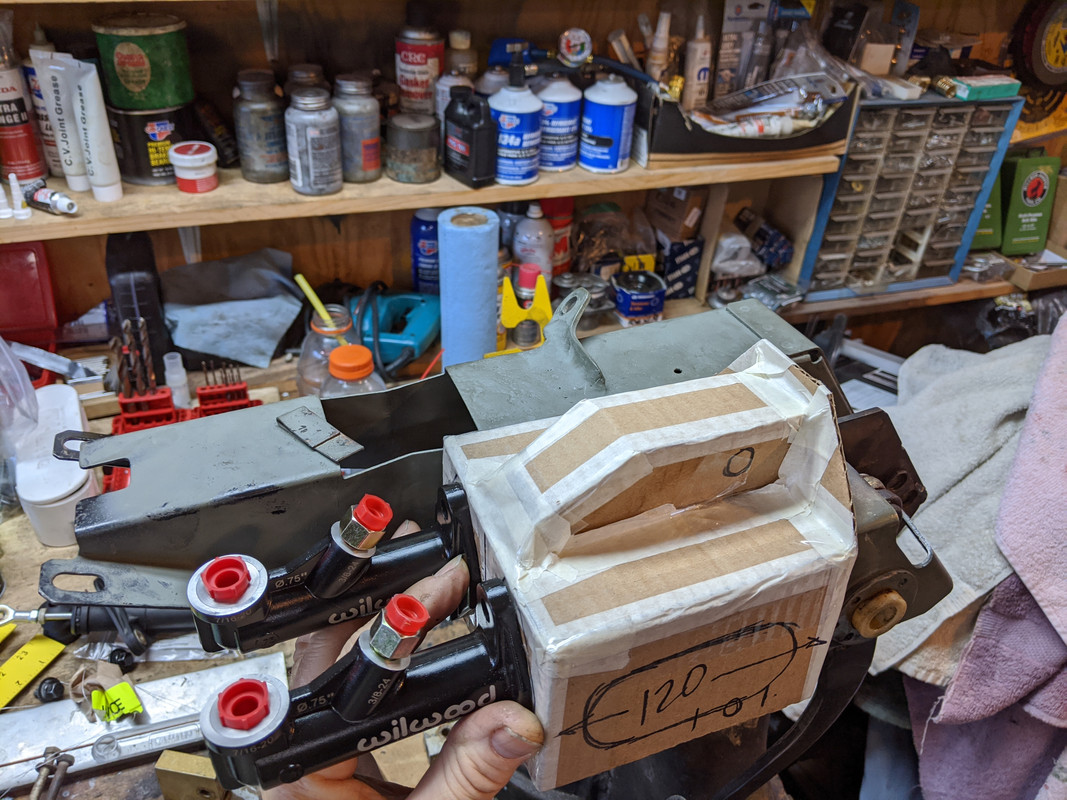
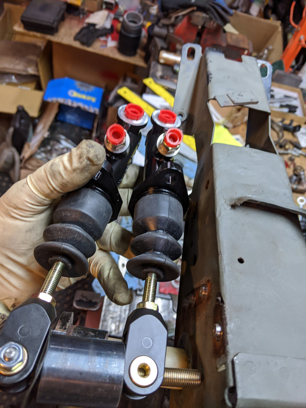
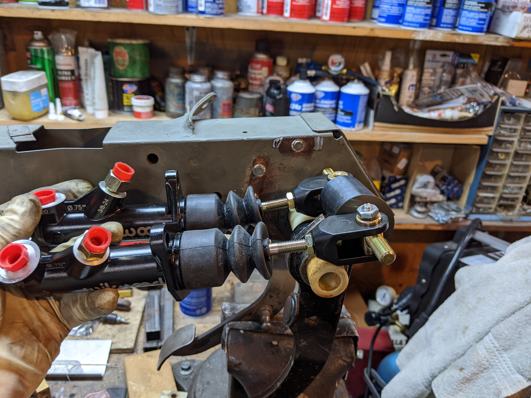
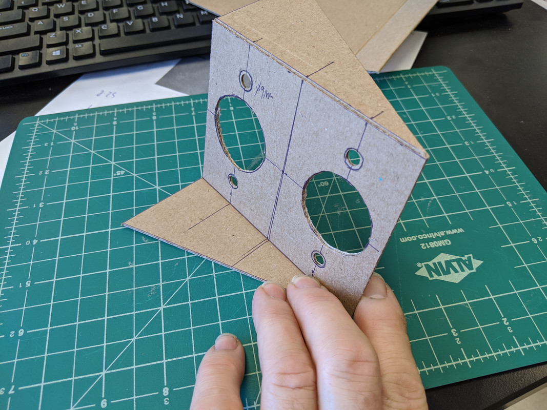
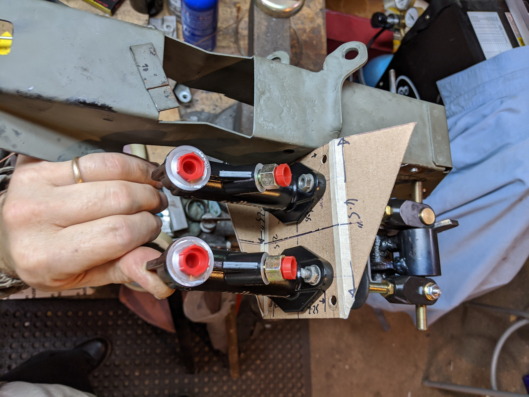
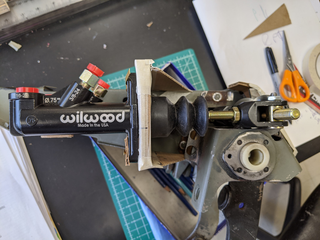
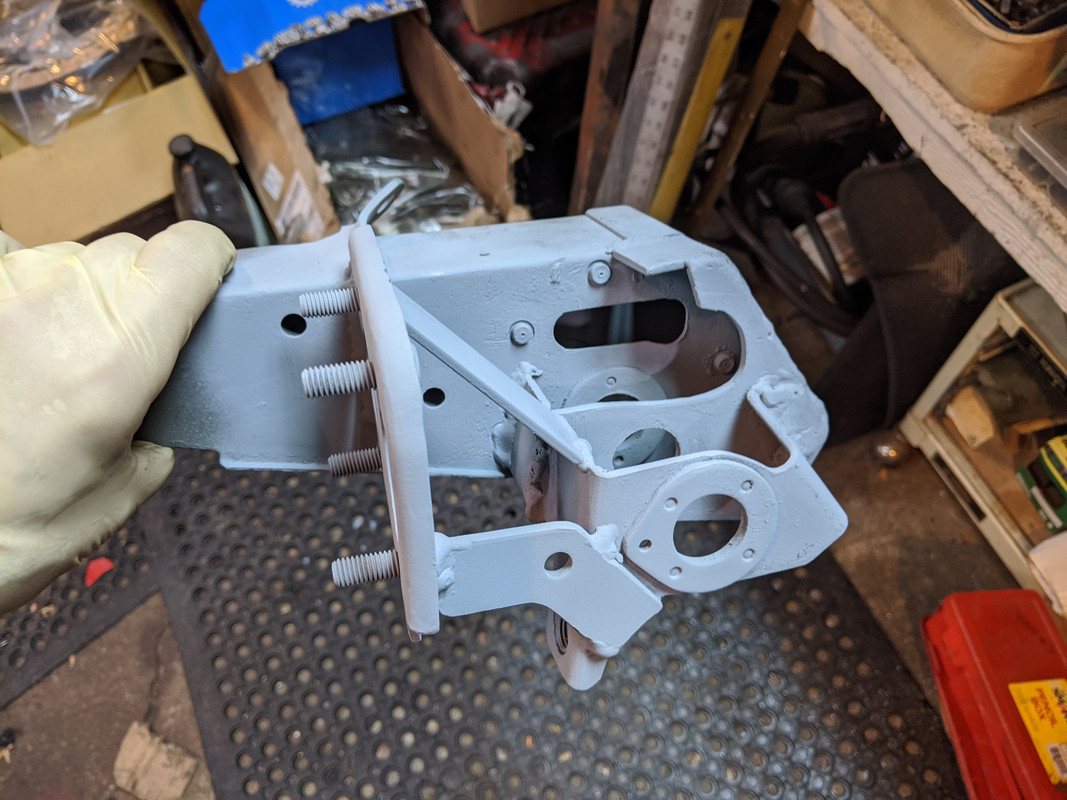
Worked on the MC mount plate mock up

IMG-20200131-075932.jpg


IMG-20200131-075928.jpg


Need to add ridge to make plate more rigid

IMG-20200131-090404.jpg


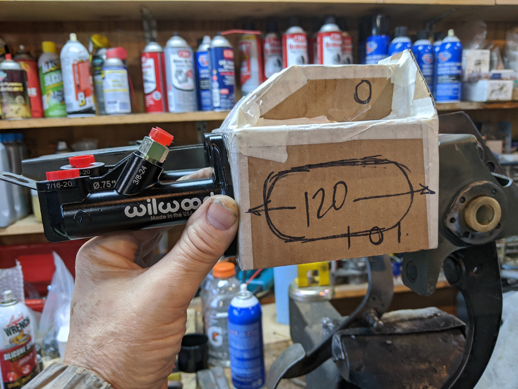
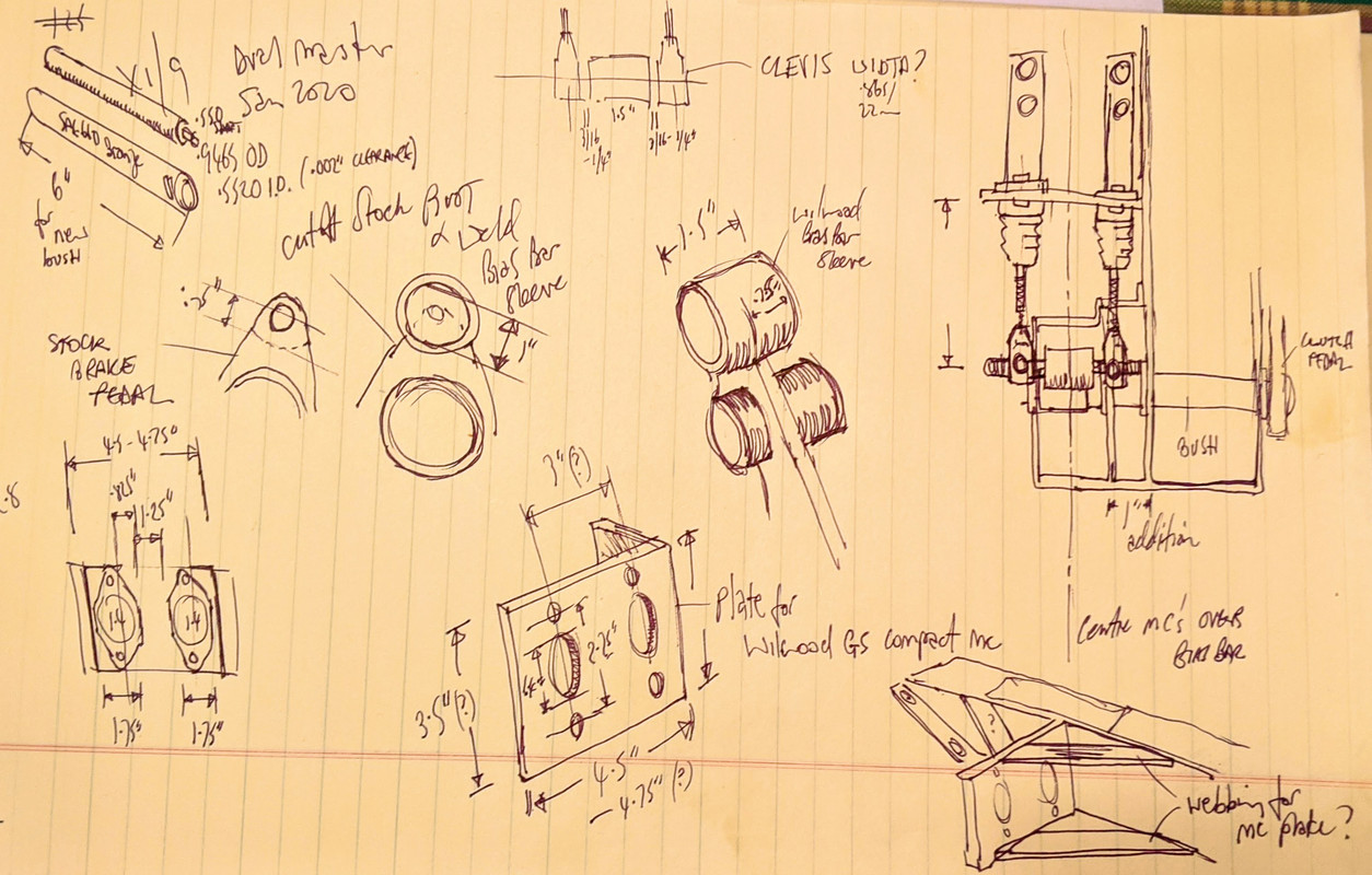
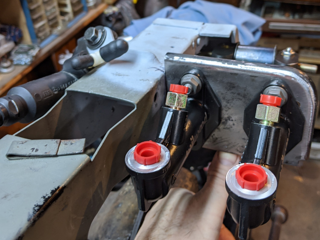
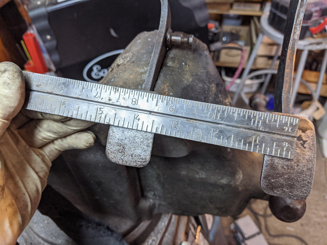
1.25" offset will be good

IMG-20200131-080116.jpg


3.25" height, 4.5" wide

IMG-20200131-090528.jpg

Will add webbing to support mount plate

IMG-20200131-090408.jpg


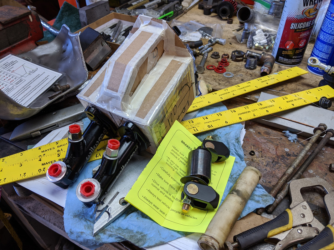
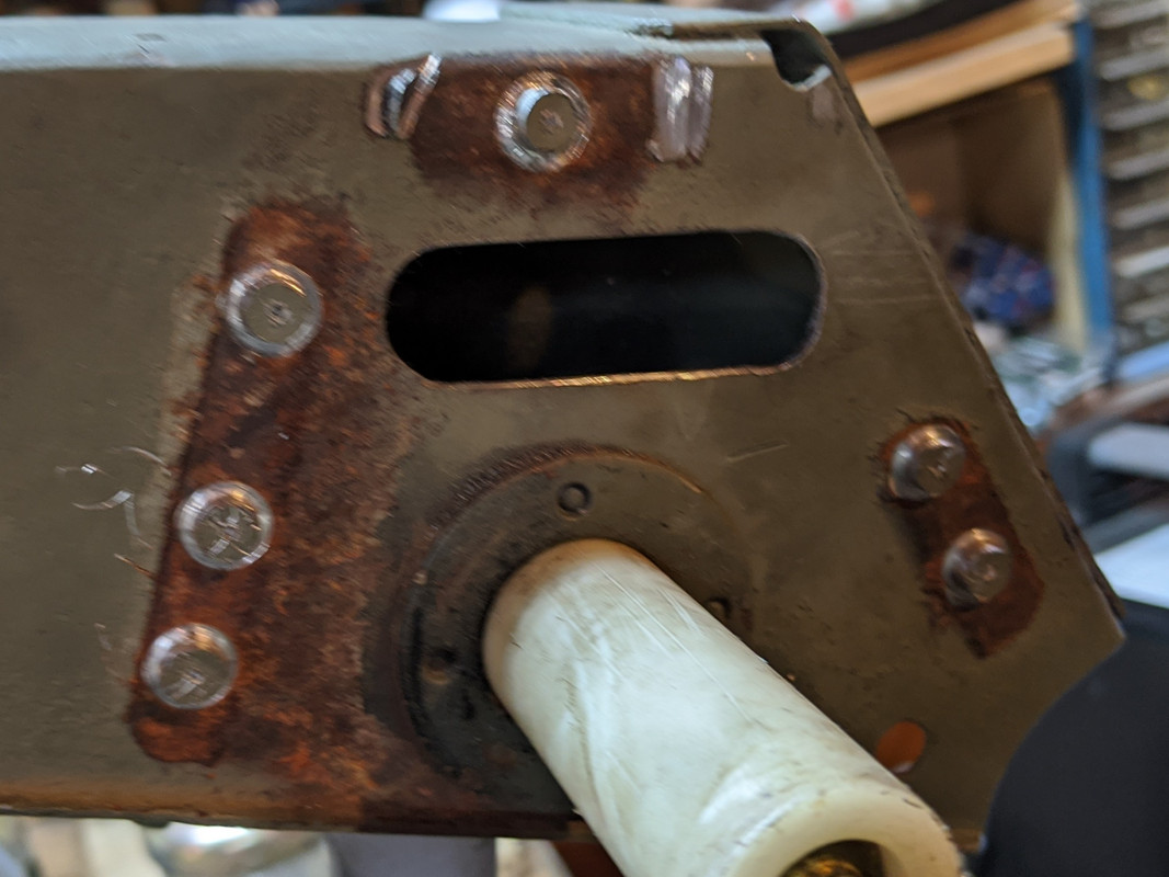
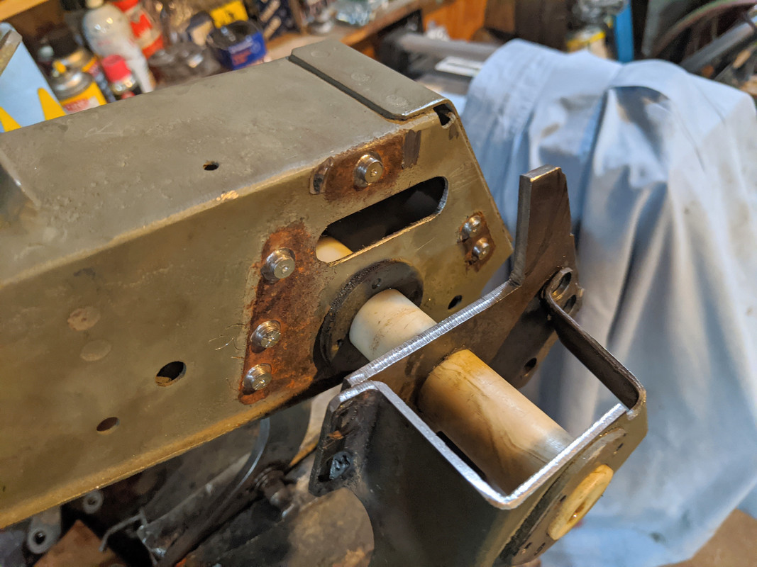
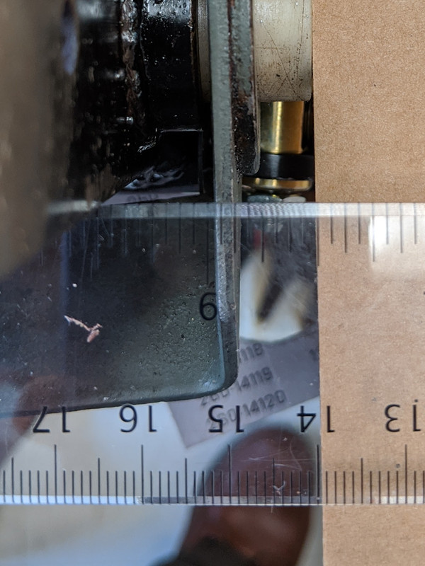
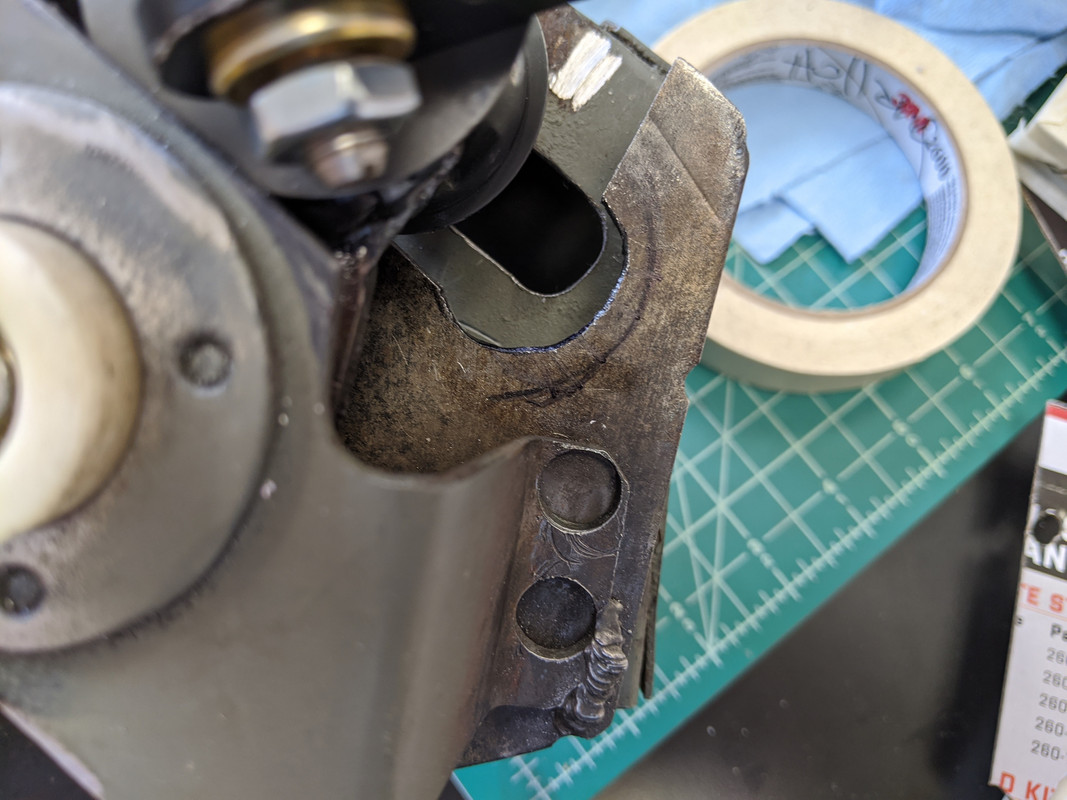
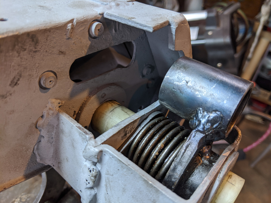
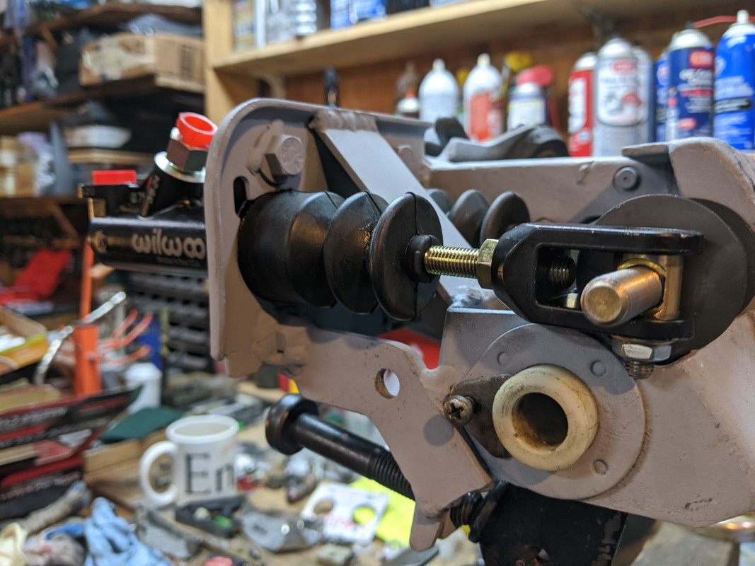
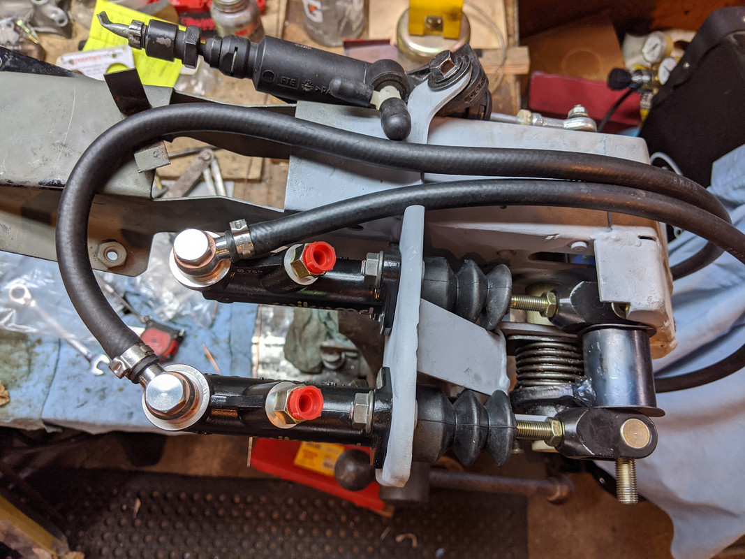
clutch pedal needs to sit approx 1/4" out for stop to sit on buffer/adjuster

IMG-20200131-094116.jpg


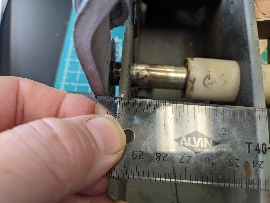
Bushing needs to be 6.375"

IMG-20200131-094232.jpg


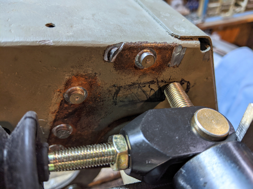
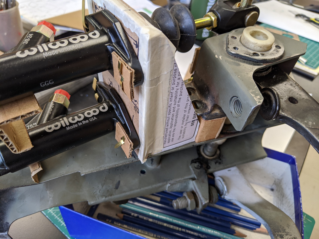
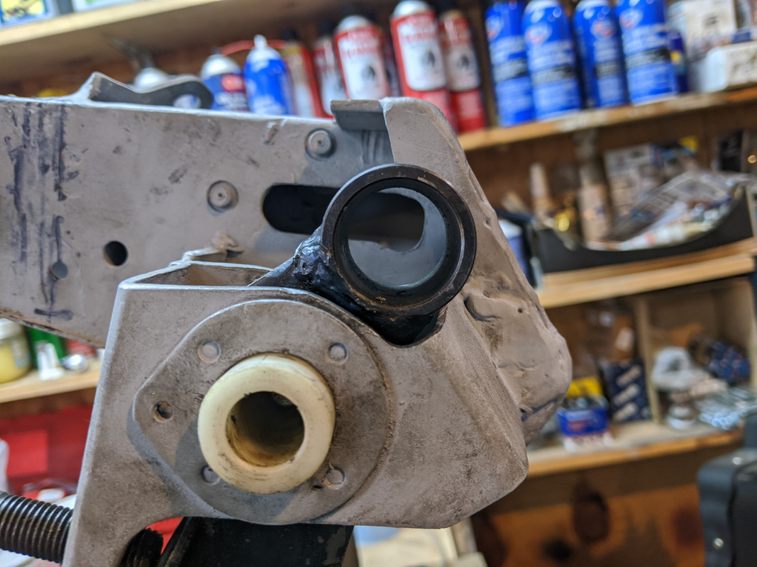
Have to cut this out more where mrker line is to allow pedal to come forward / up

IMG-20200131-094726.jpg


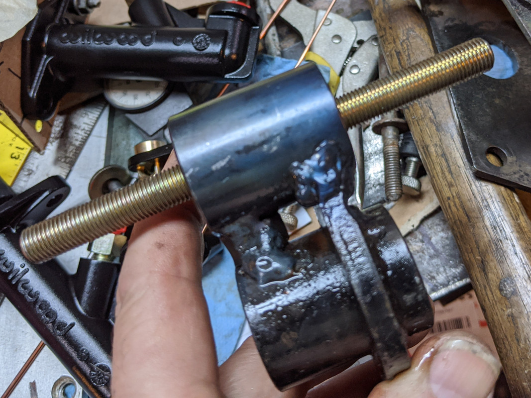
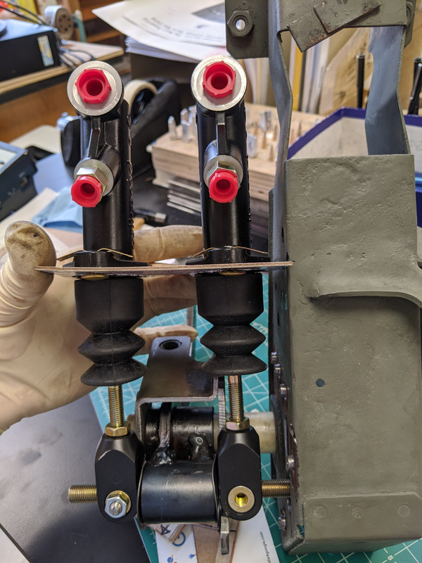
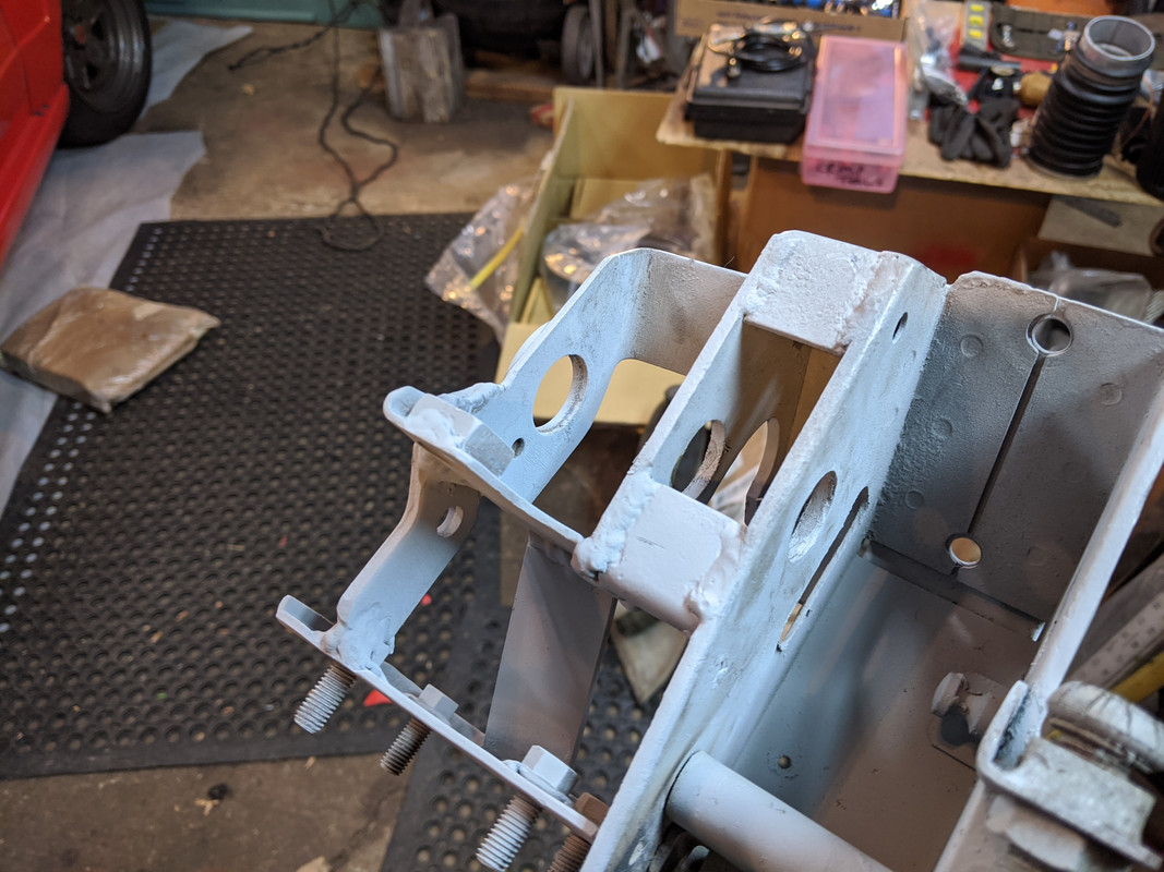
Bought some 1.25" and 3" flat bar stock to work with. Then I remembered I had a spare eBrake pulley cover from the parts car, so I cut that down. Alrady has a nice rolled edge for rigidity

IMG-20200131-170806.jpg


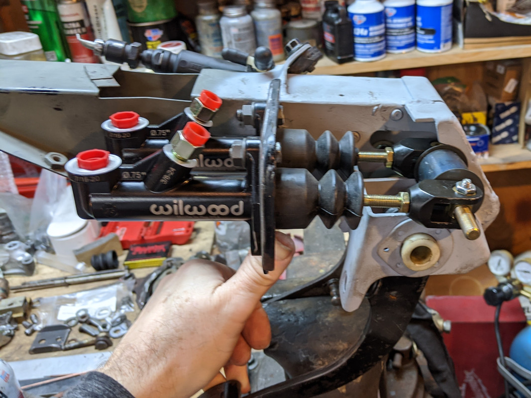
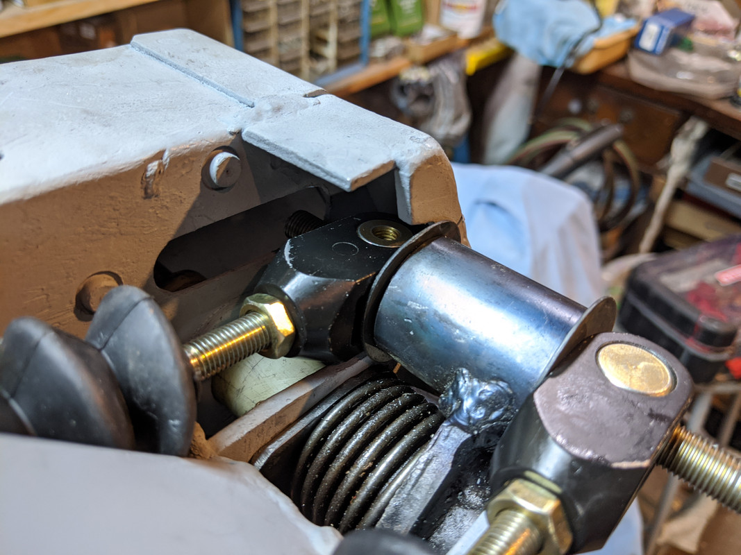
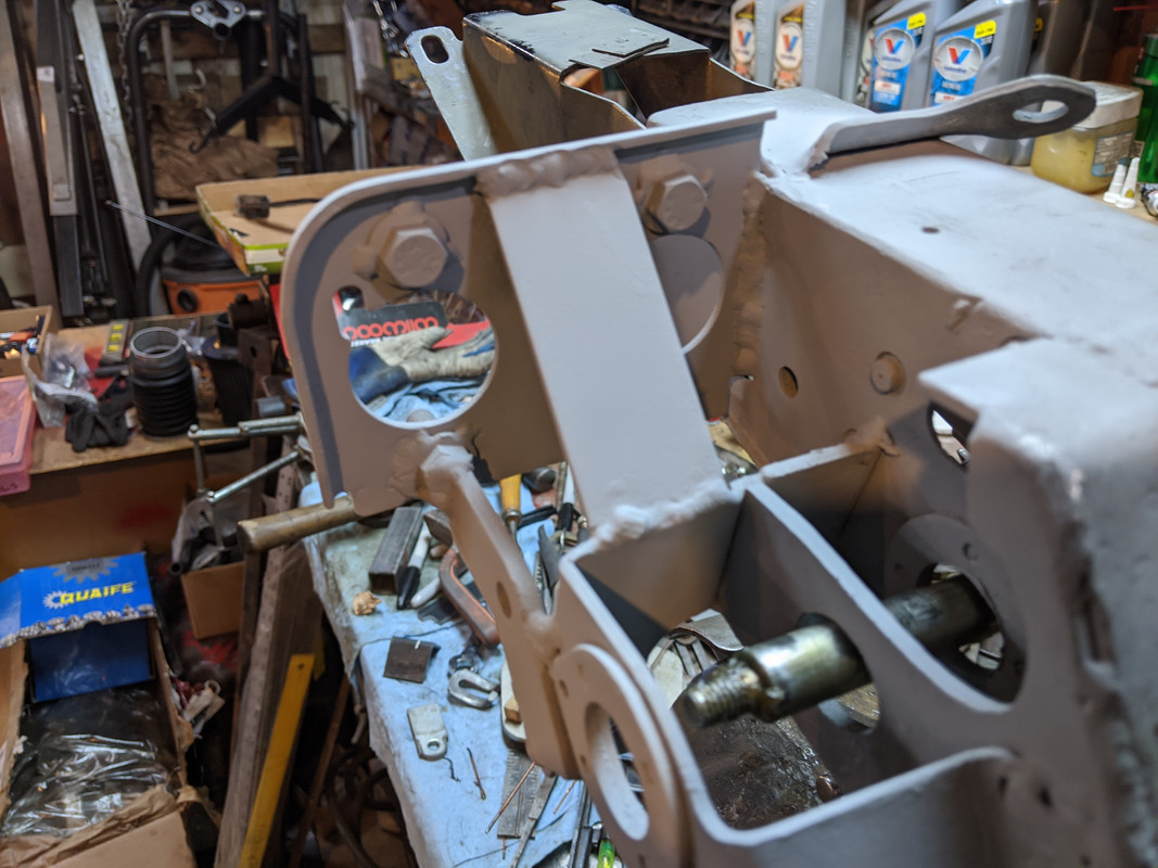
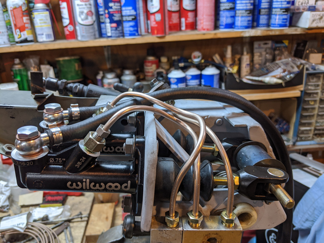
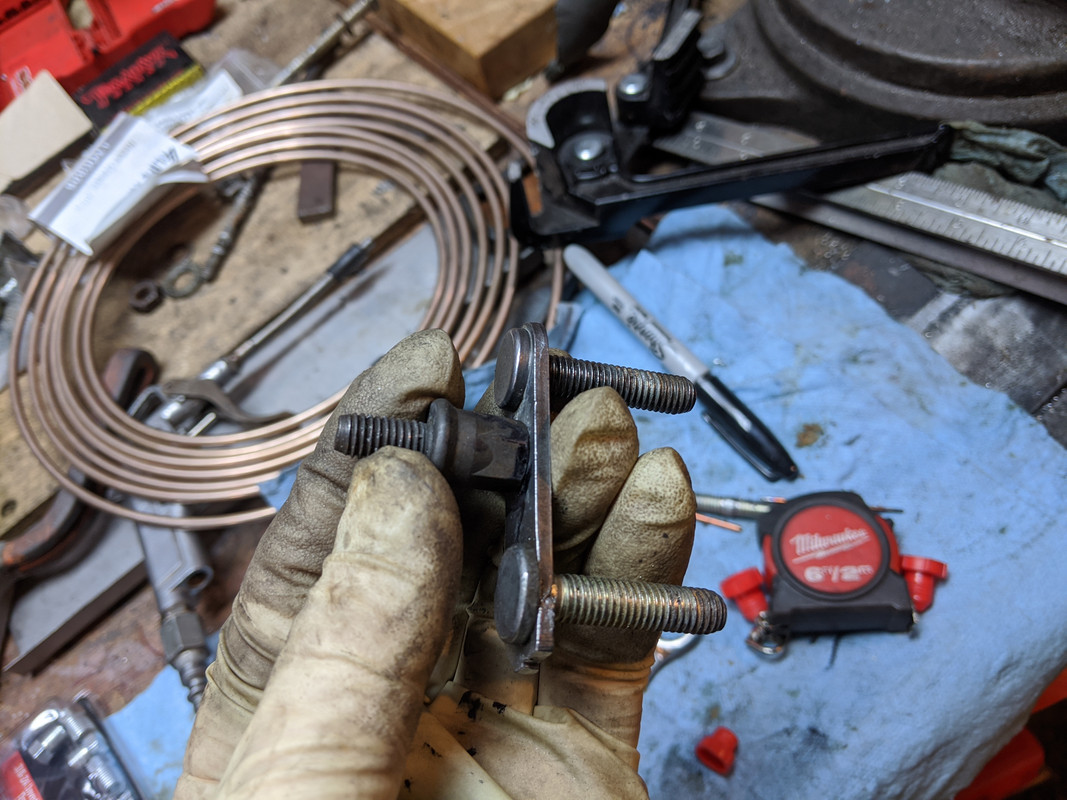
Bolts will be welded in place - reverse position of what is shown here - no practical way to access the bolt heads once the webbing is in

IMG-20200131-174514.jpg


IMG-20200131-174521.jpg


IMG-20200131-173130.jpg


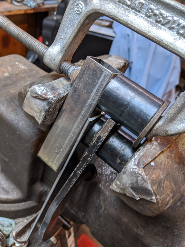
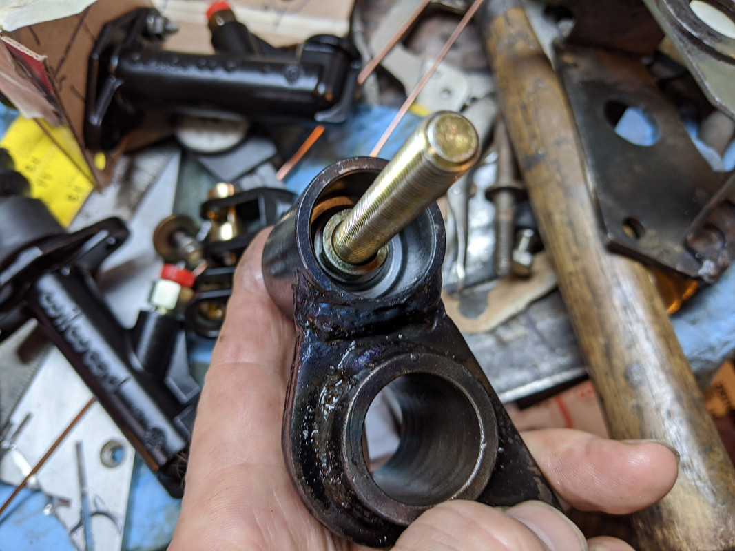
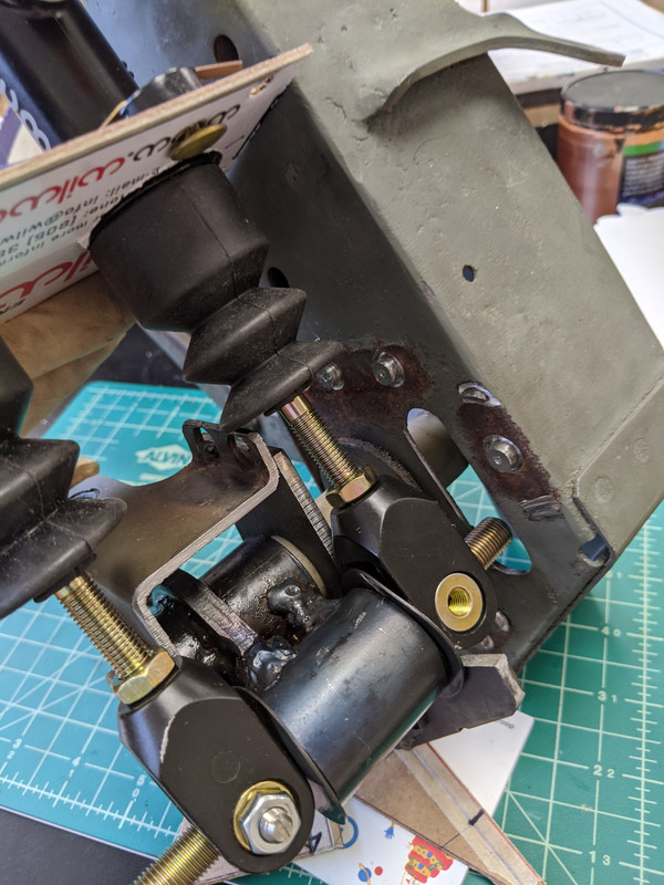
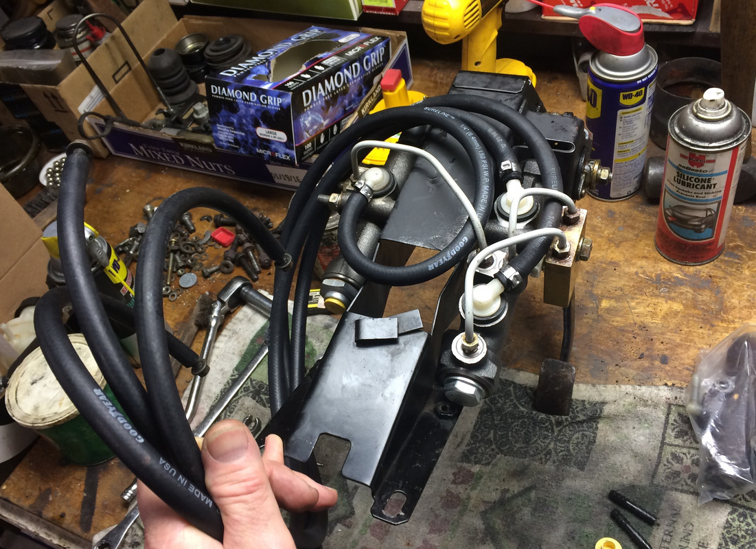
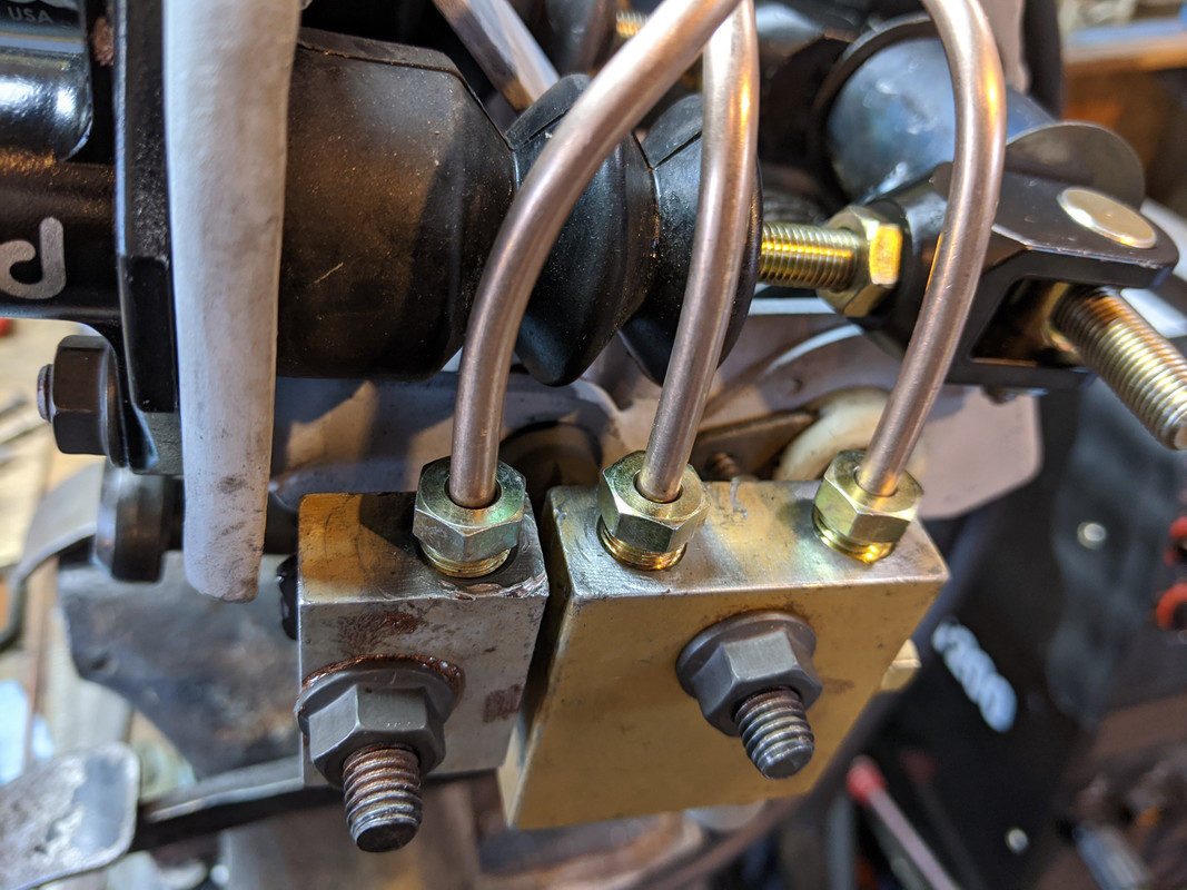
Welded the brake pivot extension

"L" section under the forward edge

IMG-20200131-173105.jpg


rear extension

IMG-20200131-173113.jpg


IMG-20200131-173400.jpg


Have to cut back the bracketry directly under the bias bar - it is just touching on the midsection plate with the pedal at full height/forward rest position

IMG-20200131-173100.jpg
 
Last edited:
Just a friendly reminder if you haven't already, make sure when the whole assembly is in position under the dash that everything clears before all of the final welding is done. ;)
 
I will not be much help. If I only took a picture at the time, but it was before intelligent cell. In the past, I bought a x19 racecar for parts. The seller wanted to keep the wilwood (or Tilton?) pedals and master. I remember the bottles were in the frunk and probably also the masters. The pedals, for sure, were still Under the dash! :D

But I have no pics and can't remember any détails.
 
I remember the bottles were in the frunk and probably also the masters.
I don't remember who this belongs to here, but we've seen this pic before:

FUEL TANK_1440509605_thumb800x600.jpg


If for any reason you wanted to add a vacuum booster to the brakes (i.e. single master), then a forward mounting position like this would make it possible. I believe someone else here has also done that too?
 
Just a friendly reminder if you haven't already, make sure when the whole assembly is in position under the dash that everything clears before all of the final welding is done. ;)

Where would be the fun in that? :D - seriously though, there is room above in that area

X19-0084e.jpg


X19-0084f.jpg


I would think that some reinforcement from the point of where the force comes from to the MC mounting bracket would be of value.

Thanks for the mockups, Karl. That is what I was working on today, once the main plate was attached. Had to work it so that there was room to install the individual components, which is quite fiddly even with no bracketry :(

Wrapping up the pedal box welding. Required assembly/diassembly multiple times to check fit, clearances, adjustments, tweaking of clearance areas around the Bias Bar, MC fitment area fettling after welding, etc.,

IMG-20200201-143449.jpg


IMG-20200201-143454.jpg


bent pedal arm again to get 4" offset back. Can't be wider, just no room under there

IMG-20200201-143515.jpg


IMG-20200201-173134.jpg


IMG-20200201-151443.jpg


IMG-20200201-151448.jpg


As Karl pointed out, can't be left as is -
IMG-20200201-161542.jpg


IMG-20200201-170731.jpg


IMG-20200201-170743.jpg


IMG-20200201-170750.jpg


IMG-20200201-171525.jpg


IMG-20200201-172946.jpg


IMG-20200201-172955.jpg


IMG-20200201-173000.jpg


IMG-20200201-173028.jpg


Brake lines from MC's have to go the this junction. Have to make those next. 3/-24 at MC to M10x1.25 (or is it 1.00 pitch, I forget) at junction

IMG-20200201-173231.jpg


Hose routing

IMG-20200201-173529.jpg


or more likely

IMG-20200201-173601.jpg
 
Last edited:
I made the brake lines today. The stock MC had two front outlets, so I needed to split the front output to two lines. I repurposed one of the stock junction boxes.

Cross-drilled the channels & tapped with 1/8 NPT to block it off

IMG-20200202-163349.jpg


Blocked off one of the outlets

IMG-20200202-163537.jpg


Lines done

IMG-20200202-173054.jpg


Rear MC goes to the single junction. MC ends are 3/8-24, junction end is M10x1.25

IMG-20200202-173101.jpg


Bracket will retain the two junctions

IMG-20200202-173232.jpg


IMG-20200202-180311.jpg
 
In wait mode - hopefully I'll get the bushing and new shaft from the machine shop tomorrow afternoon.

I painted the pedal bracket assembly in the meantime

IMG-20200205-173908.jpg
 
Back
Top