socalx19

True Classic
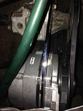
With all of the electrical upgrades I have just completed, I had hoped to wrap everything up in a nice bow just in time for Christmas by installing the GM alternator. Installation was easy and painless. My results are not what I was expecting, however.


I am getting a "good reading" of 12.3 before starting, dip to 11.1 upon crank, which I believe is just right, however voltage never reads above 12.1 after. With the engine off, it returns to 12.3.

https://www.youtube.com/watch?v=QW_fCsjfQ8U

I'm doing my research on some tests I can do - I don't pretend to fully understand all of it, but I'm able to follow directions. YouTube has been great for this. Results of my positive side voltage drop test:

http://youtu.be/MzdwNQ2xokA

With the (+) of the VOM connected to the (+) battery terminal:

At :03 - reading is .2 to .3, engine off
At :46 - reading is 3.6 to 9.0, engine running idle at 900rpm
At 1:24 reading is -4.3 to -3.4, engine revv'd between 1500-2000rpm

Also, just to rule it out, I've had the brand new alternator tested at O'Reilly's and its working properly. Since it was out, I had the old Bosch alt tested and it is fine also.

Maybe this could be executed better?


Recent work completed:
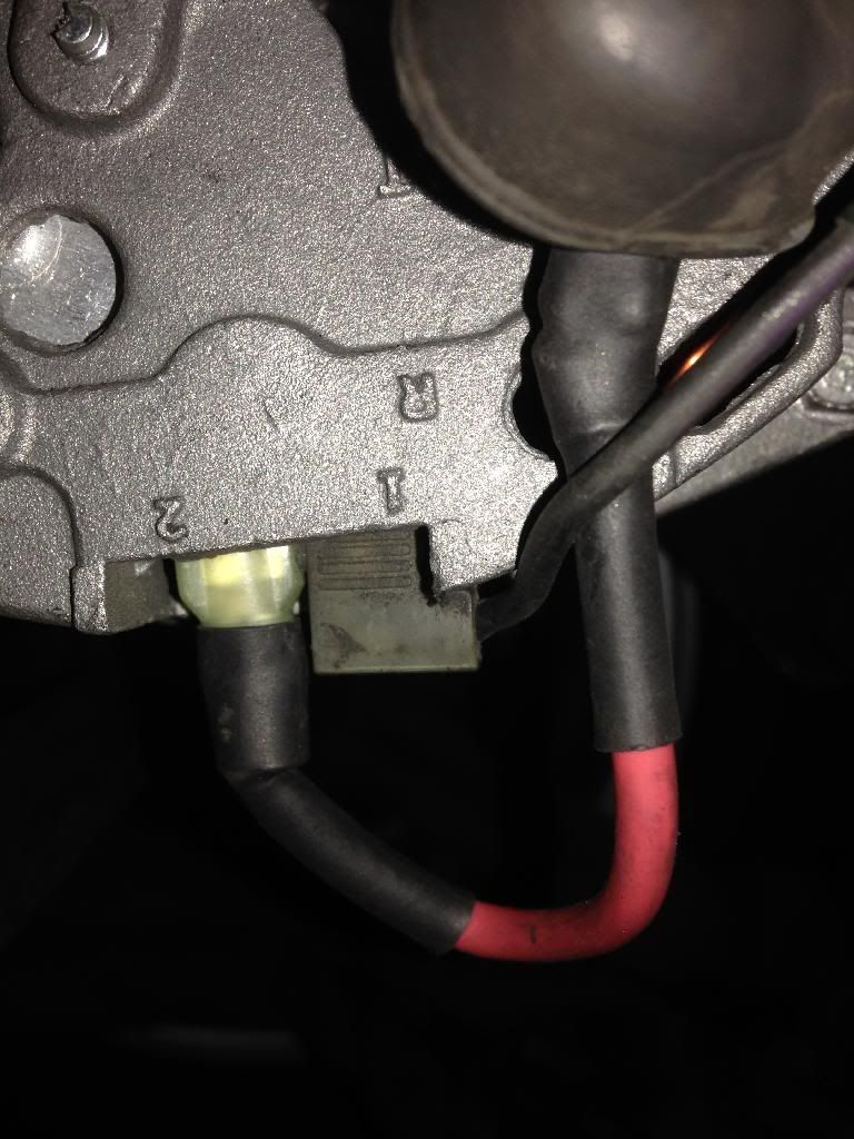
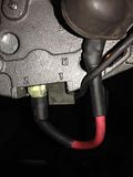
Brown wire mod
Power window relay mod
Wiper relay mod
Headlight relay mod
New ground wire from transmission to body (4ga)
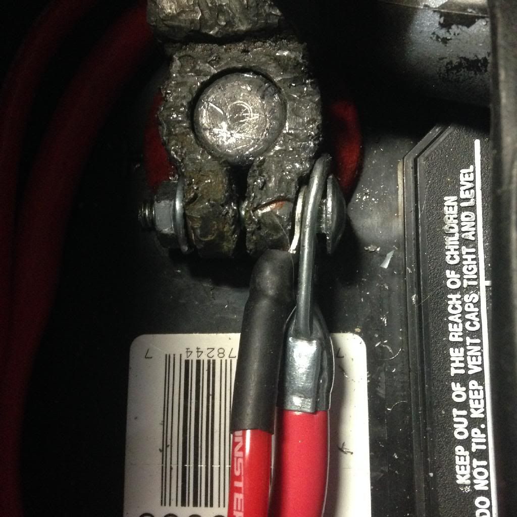
New battery terminal wires (4ga)
All ground pods refreshed

So what am I looking at here? Thanks in advance.
 
Those bolt on cable terninals are crap (your negative post terminal), you should buy a cable with crimped /soldered ends, the ground side is extremely important, as I'm sure you're aware. You should have higher voltage at the bat, esp when charging. Perhaps you don't have the exciter circuit correctly attached?
 
Good suggestion. I can solder that ground wire, no problem. If I see an improvement, I'll swap it for a "real" one. Please explain "exciter" circuit?

Few more readings -

Wipers on - 12.0
Lights on - 11.9
Wipers, lights, power windows on - 11.8
Turn signals 11.9/11.8 blink off/on
 
Those are some very odd readings. It does suggest you have incorrect connections to the alternator. Where are you applying the meter probes?

Have you got the correct charge warning light bulb in the dash? It usually needs to be a 3W bulb at least to provide sufficient excitation current. The alternator regulator needs to "see" the battery voltage via the charge warning light, which is more than just an indicator light - a small current needs to flow via the warning bulb to the regulator sense terminal in order to "excite" the alternator at start up. Once it is spinning fast enough the alternator can sustain itself. If you put too small a wattage bulb, or put an LED in there, the regulator can't get enough excitation current and the alternator never kicks off.

Measure the alternator voltage with the + probe on the output terminal and the - probe on the alternator body. Then take a reading with the - probe on the head, and then again on the car body. That will tell you if the alternator is properly grounded.

You can do similar for the battery with the meter probes placed directly on the terminals to see what the battery truly sees, and placing the probes at various points on the wiring/body to trace where you are losing volts along the hot side and the grounded side.
 
exciter circuit: one of the Alt's wires wants to see 12v before it will charge, most often you can just take that wire off the alt and connect to the big fat cable that's on there already, the one that runs to the starter/battery. looking at your pictures, looks like you got that:
CD3EEA19-824D-4A40-8D6C-2D1C83FBF60A_zps4ykcywmg.jpg

There's at least one other wire to run to the idiot light (the black one from #1?). My GM CS 130 ended up like that.

If that idiot bulb is bad: no charge.
 
Those are some very odd readings. It does suggest you have incorrect connections to the alternator. Where are you applying the meter probes?

For this test I had the (+) probe on the positive post of the battery and the (-) probe on the alt output. I was following this testing:

http://youtu.be/nQysE2oJAuo?t=8m6s

Measure the alternator voltage with the + probe on the output terminal and the - probe on the alternator body. Then take a reading with the - probe on the head, and then again on the car body. That will tell you if the alternator is properly grounded.

I am measuring 16.6 on the alt body, head and car body. Also, I did have an LED light in the instrument cluster, but I have now replaced it with a 3w bulb. Nothing has changed - 12.1 when running.
 
sounds like it's mak'n elec-trickity then, eh? maybe too much!

It would appear so! But the rest of the car ain't feeling it. I'm thinking the alt is just fine, perhaps the drop off is with the battery which has been drained more than once. Maybe I should try Tony's "good battery, bad battery" test?
 
I am measuring 16.6 on the alt body, head and car body. Also, I did have an LED light in the instrument cluster, but I have now replaced it with a 3w bulb. Nothing has changed - 12.1 when running.

Voltage regulator in the alternator or external as in the early cars?
 
How about grounding the terminal at the alternator through a bulb? Using a test light should do it - that would indicate if the issue is in your trigger wiring between the alt & the cluster ground
 
Voltage regulator in the alternator or external as in the early cars?

Internal regulator. Specs are:

  • UPC: 769754200035
  • Amperage (A): 63 Amp
  • Clock Position: 3:00
  • New Or Remanufactured: Remanufactured
  • Pulley Included: Yes
  • Pulley Type: V-Belt
  • Voltage (V): 12 Volt
  • Voltage Regulator Type: Internal Regulator
 
How about grounding the terminal at the alternator through a bulb? Using a test light should do it - that would indicate if the issue is in your trigger wiring between the alt & the cluster ground

I used a test light to confirm current through to the idiot light from terminal 1. I am also grounding the alternator with a 4ga wire to an unused post on the cam box.
 
I think the problem is with the connection between the alternator output terminal and the battery positive terminal.

Stock, the fat wire from the alternator goes to the starter, where it meets the fat wire from the battery. Is this how your setup is still? Is the junction at the starter clean and tight?

I see two extra wires at your battery positive terminal, what are these for? Is the fatter of the two a replacement connection between alternator and battery? I would disconnect both ends of this cable and check continuity. You should see way less than 1 ohm, except contact resistance between probe tip and cable, and also between cable plug and meter socket makes it difficult to measure sub 1 ohm resistances.

16V between alternator body and alternator output terminal is a problem, it means the regulator is not regulating. I assume the wire from the spade terminal labeled "2" (= remote sense) on the alternator goes to the alternator output stud? Do you have a good connection here?
 
I used a test light to confirm current through to the idiot light from terminal 1. I am also grounding the alternator with a 4ga wire to an unused post on the cam box.

Its not the alt ground that's the issue - it's the ground of the sense/exciter wire. What I was suggesting is to bypass the stock exciter circuit by providing a path to ground for the alternator exciter. With a voltmeter on the battery, you should see 13-14V with the engine running.

With the key on, not running, vBat to going out the alternator, to the cluster bulb, and then to ground which illuminates the bulb. With the car running, vBat is applied to the other side of the cluster bulb, effectively removing the ground since there is no longer a difference in potential in the circuit. Bulb will come on when there is a path to ground either due to loss of output from the alternator trigger, or through the cluster circuit.
You have that backwards, one side of the alternator dummy light is connected to the battery through the ignition switch. The other side of the dummy light is connected to the exciter. Current flows from the battery, through the bulb and through the exciter circuit to ground until the alternator starts charging.
 
You have that backwards, one side of the alternator dummy light is connected to the battery through the ignition switch. The other side of the dummy light is connected to the exciter. Current flows from the battery, through the bulb and through the exciter circuit to ground until the alternator starts charging.


Yes, you are correct - sorry for the misinformation :roll eyes:

So you would need to connect the test light between the + terminal on the Alt, and the trigger connector to provide the exciter feed.
 
Before performing the Battery "Drop Test"...

Go here and tell me you have your alt wired as instructed.

http://www.network54.com/Forum/12159/message/1142890167/GM+alternator+conversion

Your heavy brown wire should be bolted to the "post" where it is also jumpered to the number "2" terminal.


The violet/black lead attaches to the number "1" terminal (or the white lead with the spade connector in this foto). I believe you do NOT have yours wired correctly.

Also, anytime you are not getting 13-14 volts at the battery your alternator is NOT charging. Readings of 12.5 or below is simply the battery voltage.

Additionally, I would also replace the cable clamps for the battery and as others have said, the bolt-on ones can be trouble. If you TIN the cable with solder and then bolt new clamps on, and maybe even apply some more heat and solder them to the clamps, you should not have any problems with them for many, many years. I did this with my stock cables and applied a bunch of solder down the "throat" of the c lamp for a great electrical "seal" as it were. It appears your clamps are pretty well butchered though...

ANYWAY, get the alternator working first... I should be home all day, you have my number.
 
^ +1 - What Black Tooth said

If it tests correctly but not charging while in car it is highly likely to be miswired. I can not understand from the previous pictures / posts how you actually have it wired.
 
I can confirm that I did have the alternator wired as per previously discussed here - this is how I did it:


I decided to read the instructions that came with the unit then re-wired as stated here in #2:


Here is my result: 14.5v!

https://www.youtube.com/watch?v=3h5g6IKL0iE

Here's the result running lights, wipers, radio: 14.3-14.4 range:

https://www.youtube.com/watch?v=oaJyx48h0ps

I realize this isn't how it's done by everyone else, but it appears to be doing what it should. Note that I connected BAT to the starter, not as in the directions above. So the only change I have here is connecting #2 directly to the battery. Thoughts before I button up the wiring on this?
 
Back
Top