lezesig1
expatriot
Re: IMI starter assembly sold by our favored vendors.
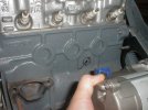
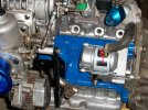
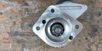
Mounted on the 850/903cc block. Notice the riding condition
on the electrical stud/nut which has been expressed by MANY, repeat
MANY people who have fitted this starter.
I'm not happy with the riding condition. (Even)
with the protective silicone cap squished against
the cast iron of the block acting as insulation.
Vibration, fatigue, and degradation of the elastomer boot comes to mind.
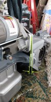
What I have done to help mitigate the riding condition is
reduced the height of the interferring electrical stud by 4mm,
and trimmed the height of flanged hexnut on that stud by 3mm.
Clamping force has still been maintained on that stud. It is now
at its barest minimum though.
Still fitting too tight to the block for my liking after the stud/nut trimming.
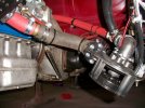
One vendor has recommended to relieve (locally grind) the block
in that area to reduce this riding condition. This seems a good
course of action providing that we don't thin it too much in that area
and create stress risers.
Anyone relieved the block in that area ? How much material is available there ?
Thanks upfront into any insight on this one.
lezesig
'72 850
Mounted on the 850/903cc block. Notice the riding condition
on the electrical stud/nut which has been expressed by MANY, repeat
MANY people who have fitted this starter.
I'm not happy with the riding condition. (Even)
with the protective silicone cap squished against
the cast iron of the block acting as insulation.
Vibration, fatigue, and degradation of the elastomer boot comes to mind.
What I have done to help mitigate the riding condition is
reduced the height of the interferring electrical stud by 4mm,
and trimmed the height of flanged hexnut on that stud by 3mm.
Clamping force has still been maintained on that stud. It is now
at its barest minimum though.
Still fitting too tight to the block for my liking after the stud/nut trimming.
One vendor has recommended to relieve (locally grind) the block
in that area to reduce this riding condition. This seems a good
course of action providing that we don't thin it too much in that area
and create stress risers.
Anyone relieved the block in that area ? How much material is available there ?
Thanks upfront into any insight on this one.
lezesig
'72 850