Bertone X1/9 fuse panel feed/brown wire/junction question

Fiataccompli

Chris Granju
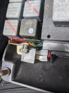
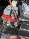
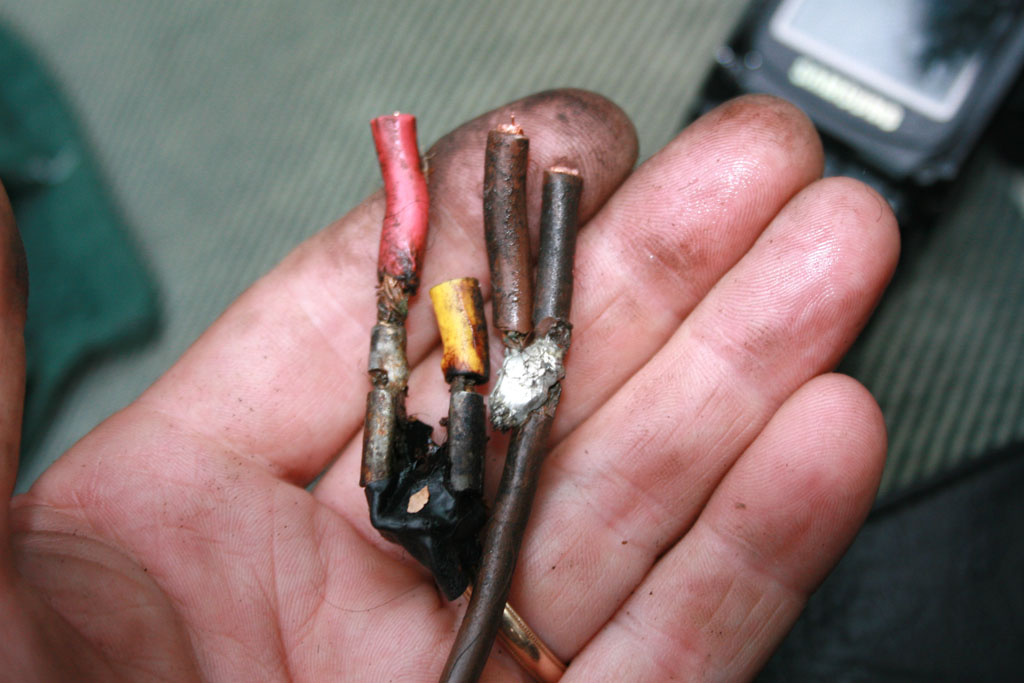
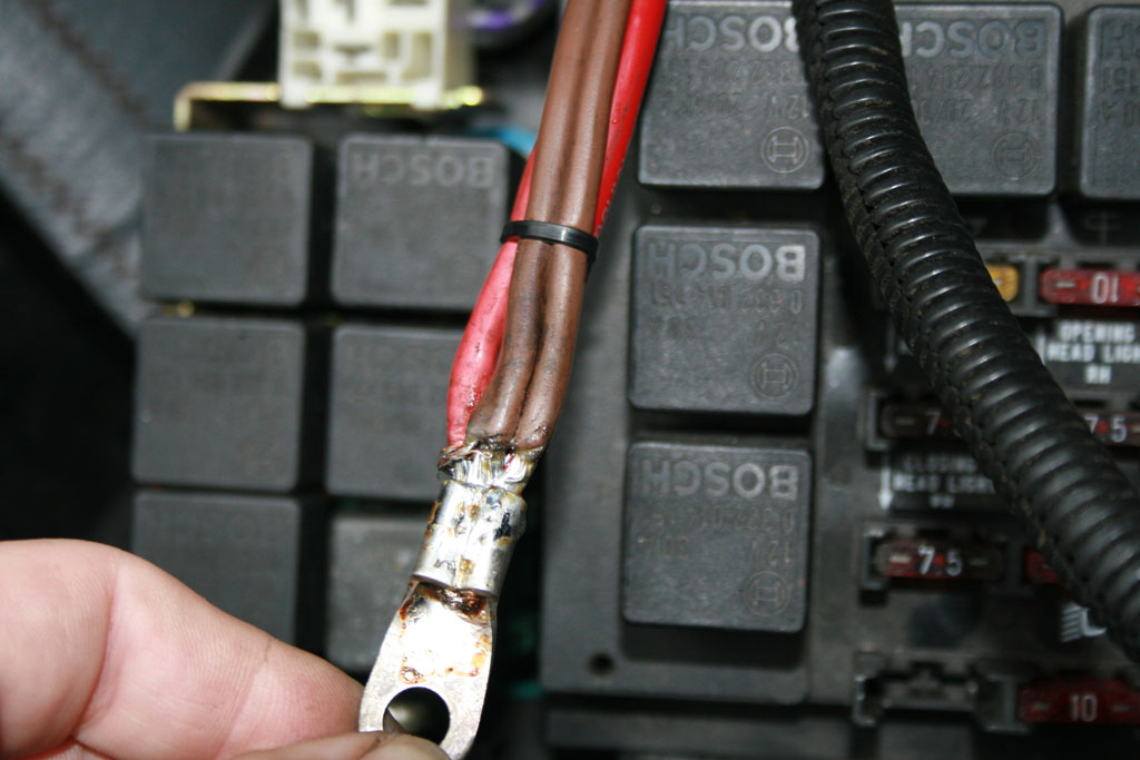
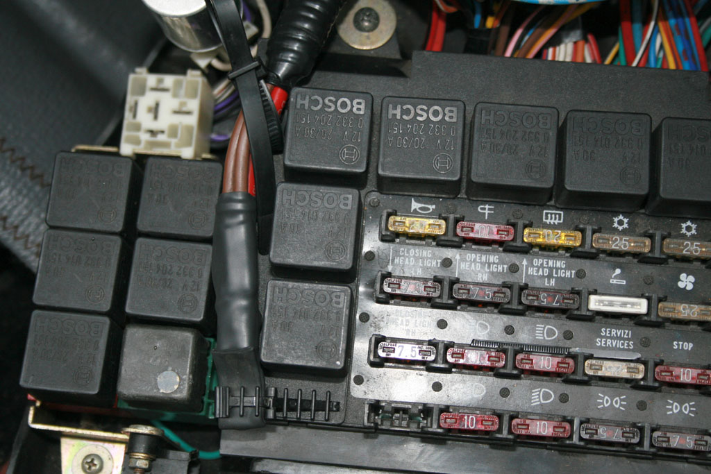
this may be a very dumb question, but I was having trouble finding a clear visual or description on what the factory entry point for the + lead into the fuse panel, brown wire, etc junction actually is. My car has 3 wires (2 from battery & brown wire to I presume ignition) joined with a wire nut. Remarkably, this works and has not been a problem source yet as I've been sorting things out little by little...but it's time to clean it up. At the very least (or temporarily), it will be soldered and heat shrinked. Would a power distribution lug of some sort be better? I'm guessing this is also where I need to pick up the feed for relaying the low beams (can't say I know where the + for the factory relayed high beams is sourced). Guess I'd like to know what others have done with success for this. Clearly the wire but thing was effective enough for whatever issue the PO was having, but it's a little too much for me to leave as is! Thanks in advance.

Chris G
85 x19
 
On the '85 to '88s, the large gauge brown wire from the battery went into a 4 spade terminal block attached to the bracket that holds the 6 relays to the left of the fuse/relay panel. One of the wires that comes out of that goes to the fuse panel for unswitched 12V and the other goes to the ignition switch for switched 12V. The amount of amps going through that block created lots of heat and can melt it, so a PO probably swapped it out and just tied the three wires together with a nut. Here's a picture of the fuse panel from a used one I picked up. You can see the black junction box on the front of the 6 relay holder.
IMG_0527.JPG


Here is a close up of it showing the meltdown.
Bertone fuse box 07.JPG


This is the rational behind the brown wire mod. It is best to get a power distribution block with fuses to supply power to relays for the headlight mod, wiper mod, etc.
 
Thanks. Okay, that make sense on all levels. Don't know how many circuits I would end up wanting to relay but having the option in a clean way is desirable.
 
Currently, the serious Xheads in DCfiats have relay kits for their wipers, the headlights and the electric windows. In an ideal world you probably don't want current directly from a Fiat ignition switch to anything.
 
I appear to be getting serious & I have a car with their sticker on a window, so maybe I need to get on the ball here! I believe the '85 already has relays for high beams & window motors. I should not say anything about the wipers on this car for fear I will jinx them, but suffice it to say that I have not had concerns about wiper performance. Switch wiring capacity noted however.

So, do those serious Xheads install a nice input/distribution block in place of the problematic connector that seems to melt per factory spec?
 
This is what mine looked like
X19_1138.jpg


I added an extra feed from the battery terminal and crimped them all as one. EDIT - soldered at the time - I would not do that again, just get the proper crimp tool for heavier gauge terminals.

X19_1133.jpg


tucked in-between to avoid cable stress
X19_1134.jpg
 
Last edited:
I ran an 8 gauge wire from the battery to a new distribution block took all the wires that were in that plastic square junction box and hooked them to the distribution block.
 
I went to a Father's Day Car Show today, and when I went to leave the car was stone dead and wouldn't take a jump. Even the chime didn't ring so I checked the fuse box and found that the brown wire connection was totally melted (picture below), and after a simple "wiggle" the car started right up. I'll bet I melted the connector when I was having my starting problems (I cranked so much then I burned out my starter) and it was a problem waiting to happen. The plastic connector crumbled away, and after cleaning up the spade it starts fine. Maybe I'll do the brown wire mod after all.

Melted!.jpg
 
I went to a Father's Day Car Show today, and when I went to leave the car was stone dead and wouldn't take a jump. Even the chime didn't ring so I checked the fuse box and found that the brown wire connection was totally melted (picture below), and after a simple "wiggle" the car started right up. I'll bet I melted the connector when I was having my starting problems (I cranked so much then I burned out my starter) and it was a problem waiting to happen. The plastic connector crumbled away, and after cleaning up the spade it starts fine. Maybe I'll do the brown wire mod after all.
Definitely remove that. The connector melts due to excessive resistance from poor connection, so it won't get better. Cut the spades off & either replace with like, or crimp them all together as one, just don't solder them, it's not good practice for automotive. I used to do it, and have changed my ways :)
 
I went to a Father's Day Car Show today, and when I went to leave the car was stone dead and wouldn't take a jump. Even the chime didn't ring so I checked the fuse box and found that the brown wire connection was totally melted (picture below), and after a simple "wiggle" the car started right up. I'll bet I melted the connector when I was having my starting problems (I cranked so much then I burned out my starter) and it was a problem waiting to happen. The plastic connector crumbled away, and after cleaning up the spade it starts fine. Maybe I'll do the brown wire mod after all.

View attachment 74470
Running a second wire to the same junction area isn’t a bad idea. Going to ring connectors so they are through bolted is a good idea. Less heat in each supply cable will mean less heat to each of the cables. Going 1:1 for the two cables makes a lot of sense given the loads.

Adding the appropriate relays will unload both cables (all the switched power going through the ignition switch and the constant supply power going to the fuse box and the relays), so starter relay, low beam relay and wiper relays will all pull load off the fuse box and the ignition switch.
So only three of the four male spades in that junction box are used. If I add another piece of 8 gauge wire from the battery can't I just use the open spade to connect it?
 
Mike I agree with the others, do not retain that stock connector unit. Completely eliminate it and connect all of the power wires (including a newly added one) to a power distribution block/post. This applies equally for the earlier X models. They have a similar thing but with a very different style 4-way connector. And it is also problematic like the newer style. Simply too much current/heat for the plastic housing to handle. No sense trying to "repair" the original one, replace it with a better design. Something like this works well:
download (1).jpg
 
So only three of the four male spades in that junction box are used. If I add another piece of 8 gauge wire from the battery can't I just use the open spade to connect it?
I would personally abandon the spade approach. Having a bolted connection as shown by Dr Jeff above would be my preference with an insulating cap (most come with one.)

Using ring connectors secured by the fastener, some dielectric grease and you will never have a change in the resistance. I would stack it with power from the battery, the two leads (one to the fuse box and the other to the ignition switch) and the second power supply from the battery on top.

Alternatively you could use two separate assemblies and keep the ignition and fuse box supplies separate.
 
Last edited:
Thanks guys! First, I purchased the negative cable Bob suggested in the negative battery cable thread. Big difference in the gauge for sure. I purchased a terminal lug as suggested above, and installed it in place of the spade junction box. Next cut off the spades and installed lugs, then ran an additional 8AWG wire from the battery to sister with the existing 10AWG brown wire. I got lucky that the prior owner has an alarm wired in (that I've removed) which left a predrilled passthrough for the new wire. The car wasn't hard to start up before, but starts on the first or second crank now. Good times!!
 

Attachments

  • Ground.jpg
    Ground.jpg
    146.7 KB · Views: 166
  • Old connectors.jpg
    Old connectors.jpg
    116.4 KB · Views: 150
  • lugs.jpg
    lugs.jpg
    109.7 KB · Views: 162
  • Final product.jpg
    Final product.jpg
    99.5 KB · Views: 165
Thanks guys! First, I purchased the negative cable Bob suggested in the negative battery cable thread. Big difference in the gauge for sure. I purchased a terminal lug as suggested above, and installed it in place of the spade junction box. Next cut off the spades and installed lugs, then ran an additional 8AWG wire from the battery to sister with the existing 10AWG brown wire. I got lucky that the prior owner has an alarm wired in (that I've removed) which left a predrilled passthrough for the new wire. The car wasn't hard to start up before, but starts on the first or second crank now. Good times!!
Looks great.

So you have a cover for that power terminal assembly right? You might adjust the relationship of the main supply wires to better be conformal to each other and reduce the stress on them when you close the fuse box assembly

Hint hint… :)
 
Last edited:
Can I be a little lazy and just ask you experts which switch does each of these go to? (‘87 model)
image.jpg
 
Can I be a little lazy and just ask you experts which switch does each of these go to? (‘87 model)View attachment 77511
I recently answered this. I will see if I can find that thread.


The late wiring diagram is also in that thread for download.

Yellow goes to your rear defrost
Large White is hazard switch
Red interior light switch
Green goes to the power antenna switch or perhaps in your case the fog light.
Small White to rheostat
 
Last edited:
Back
Top