Coolant Pipe Rework Surprise! Pipe Maker?

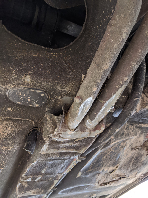
Alrighty then I think we have answers: The Coolant pipes stick out the front far enough and the original set up for the heater pipes is to connect the hose from the Head to the Heater Valve Pipe under the dash.

So the heater pipe that "used to" run through the inside of the car is the Water Return and connects to the Heater Tube Pipe. Correct?

Oh and remember my Lord Fusor curing problems? Well that was during winter and took weeks to cure. Now during the summer it starts to kick in about a half hour!!! And this is the medium speed Fusor. Final tunnel box mounting will be next week on a foggy cool morning!
 
So the heater pipe that "used to" run through the inside of the car is the Water Return and connects to the Heater Tube Pipe. Correct?
I think it's the opposite: the hot side.

Here's a nice shot from the FIAT parts catalogue:
Screen Shot 2018-06-14 at 6.43.06 PM.png
This is for the non-ac and early model ('74). Again, I think in practice that the "hot" tube from the engine terminates ahead of the return line which is different than the drawing shown.

Hope it helps.
 
So the heater pipe that "used to" run through the inside of the car is the Water Return and connects to the Heater Tube Pipe. Correct?
I'd have to go look on my car to remember. But Darin knows his stuff so I'd go with that. However, as we said it really does not matter which one was what on the stock layout. Because you are building a custom system and can assign either tube to either path (depending on how you want to plumb it). But I believe the convention is to have the "hot" water go to the valve first, then to the heater core, and back to the engine. So route the tubes accordingly, independent of what it was stock.
 
The (original) in car tube is definitely the hot feed to the valve. The soft hose from it goes through the bulkhead and attaches to the head port. As Jeff said, with yours, you just need to make sure the valve connects to whichever you choose to attach to the head feed port.
 
Are you sure about the flow direction not mattering?

years ago I had a Ford Maverick that I got cheap and put a motor in and could not get the heater to work. (even installed a 12v pump).

then on a well it won't make a difference but I got nothing to lose, I swapped the hoses (flowing the water the other way) and I had a GREAT heater!!

(I swapped it again just to see and again no heat)
 
Hi Rod, a bit of misunderstanding.
We are not saying it does not matter which way the water travels through the heater. We are saying it does not matter which pipe he uses for either side, so long as the related attachments of the pipes directs the water to the correct side of the heater. Due to his system being completely remade he can assign either pipe to either function, he just needs to then connect those pipes accordingly, to assure the correct flow as you said.
Hope I was able to say that without it sounding like a line from Austin Powers ["Allow myself to introduce...myself"].
 
Ahhh, I thought you were asking about the attachment to the new heater pipes discussed before.

As for your prior experience, I assume it had something to do with the design of the valve. Perhaps it was something of a "trap door" style, so when the water flowed in reverse it pushed the door closed? Not really sure if it was designed intentionally to only flow one direction, or if it was more of a consequence of the particular design that was needed for other reasons. Perhaps the design of the cooling system was such that if the heater were to flow backwards it would interfere with some aspect of the system's ability to properly cool the engine? Mostly guessing here. But for whatever reasons I've always known heaters to flow to the valve first, then to the core. I assume it is to help prevent flooding in the event the core springs a leak (which seems the most common location for a heater leak in my experience).
 
It really doesn't matter where the heater valve is placed, unless the design of the valve is directional. The flow path is dictated by the cooling system/engine design. On mine, the original valve is stuck wide open. Since it didn't leak, the OP simply had a manual valve added on the return line over the transmission. System works just fine. I replaced that with a vacuum operated valve so I can control it from the cabin, but kept it in the same location.
Once the valve is fully closed, regardless of location, the circuit is 'dead' - no flow can occur & no heat transfer takes place. Feel the temp of the feed hose with the heat off, you will see what I mean.
 
Tunnel box and pipes are officially mounted!
20180627_122624.jpg 20180627_123001.jpg

Time to connect in dash heater hoses and somehow with what everyone has said I got confused on what connects where. I understand that in my case it's just a matter of making sure they connect correctly to the engine but I want it like it was stock.

So one more time - does the hose from the head connect to the heater valve OR to the return pipe off the heater?

Thanks

P.S. You can't show a Fiat schematic and say you think it is the opposite! My brain can't comprehend that, lol.
 
Hose from head connects to the heater valve.

Regarding the PS, the opposite part was the layout of the tubes as they emerge up from the tunnel, so safely ignore it. You can trace it yourself knowing the head connects to heater valve.

Your pipes all mounted look amazing! Nice work.
 
Thread Revival.

Since I have to rework the box due to damage, I'm thinking I need to do the SS pipes to avoid jinxing myself DTR.

IMG-20200502-174203.jpg


I see several mentions of the SS pipes coming from BRMS (I think) - but no links or contact info for the manufacturer. Does someone have the relevant info?

EDIT: Found Dan linked another thread, with a post from Bernice, with the website link
 
Hey Hussein,

You are right and here is Rick White's email - rwhite@bmrsusa.com and # 704-793-4319.

If you tell him you want what I had built he should be able to do it as he keeps all cnc files. Since I don't weld I cut metal pieces for the ends to fit around the pipes then used Fusor to weld the ends closed. I also glued on with the Fusor strips of metal to cover all the holes left from drilling out the box (62 holes I think). I ended up screwing the box to the floor in about 10 places with the Fusor. I'm sure you will be welding!

This is what I ordered from Rick, he had made 3 out of the 4 pipes before. My 4th pipe (heater) was shorter so i could fit it in the box now. All SS.
  1. Two (2) Coolant Pipes, Right and Left without any drains.
  2. One (1) Heater Pipe, just like you made before.
  3. One (1) Heater Pipe with 2 dimension changes. A) The riser needs to be 1” shorter. B) The long straight of the pipe needs to be 1 1/8” shorter. (When I assemble the pipes the 2nd heater pipe will sit just above the 1st heater pipe in the tunnel box i.e. why it is shorter in two directions.
I've included the invoice and images of the 4 pipes in the box along with my original drawing I gave him to work from.

Any questions feel free to ask!

Carl


Heater Pipes Stacked new.jpgFront Pipes Box.jpgFront Coolant to Rad w (2).jpg20180625_122329.jpg20180625_122338.jpg20180627_122624.jpg20200611_202051_resized.jpg
 

Attachments

  • so235662_0.pdf
    5.1 KB · Views: 127
I ordered the same tubes, but I asked that they move the location of the drain ports to the side like the originals. They had no problem accommodating my request, but if I didn't ask they would have placed them at the bottom of the tube. If they would have been there on your car when you went off road they would have been torn off.
 
You can also request that they not put the drain ports in at all.
Draining the tubes is best done by removing the hoses from the ends anyway.
You want those deposits out of the tubes, right?
 
Alright. Pipes are ordered. Shoudl be only couple weeks turnaround. I'm stuck off my feet for another week with the foot surgery recovery, so not much I can do besides plan my basic approach to the tunnel reattachment at this point.
 
Back
Top