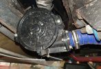
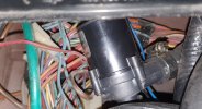
This is exactly what I did. I use the craig davies water pump, which is smaller and a bit cheaper than the BMW model. I still have the stock thermostat, and I have the pump between the thermostat housing and the new pipe that I had made that replaced the mechanical water pump.

I run my pump permanently, while the ignition is on. I did try running it at different speeds using a pulse width modulator, to be honest slowing down the pump only maintained or increased the temperature. So in the end I removed it.

Great thing with this set up, once I threw a fan belt and the car continued to run without overheating. Also I find that on a hot day when I stop in traffic the engine temp goes down and not up like it used to.
If I recall correctly, your new pipe from the original T-stat to the new E-pump and the block-off plate on the engine also reroutes it away from the exhaust manifold (like the stock return pipe is)?
 
May I ask, why you kept the half of the water pump on the engine block, instead of making a plate that will connect the pipe to the engine block directly?
What are the advantages by doing this?
I am asking because I am thinking to make a conversion like yours.
Pretty much my only justification for doing this is the reduction in fabrication work needed, so that I did not have to figure out how to create an adapter from the engine blocks port to a standard pipe.

The stock water pumps inlet may be a slight restriction, but I don't think its a huge ordeal. I will add - I went with a CWA200, as that is advantageous for me (I have multiple vehicles that use one), but after looking at the impeller design of each, I would just go with a CWA400 tbh. Should be a minimal efficiency difference, and can be capped to a reasonable speed using the tinyCWA if it is excessive.
 
Just my opinion, but I think some of it might depend on whether or not you intend to retain the stock thermostat function vs utilizing a electronically controlled T-stat to control the electric pump. If the stock T-stat arrangement is to be retained, then keeping the stock water pump housing as well as the "water return pipe" that connects them is a far easier approach. Why would you want to retain the stock T-stat? At least for the X1/9, given the overall coolant system layout, with two large hoses connecting to the two metal pipes running to the front mounted radiator, and the internal "bypass" T-stat design between them, it avoids having to redesign those components. In other words it's a much easier task to keep it. Kind of a 'all or none' situation I suppose; change a whole bunch of stuff, or keep it simple and just change the water pump. Personally I would change everything, but that's just me.

I think someone else took a slightly different approach to converting the water pump to a electric one. They used a different style E-pump and they replaced the entire stock one with a block-off plate as you suggest. So it is one viable option.
Yeah, I wanted to retain the stock bypass thermostat functionality as my goal for this project was giving the engine the best possible conditions I can provide for longevity. As we all know there's an exhaustingly large amount of me blabbering about the theory behind this in the first 5 or so pages. One day when I get back to driving the thing I'm going to condense everything into a single concise post to make it easier to follow.
 
This is exactly what I did. I use the craig davies water pump, which is smaller and a bit cheaper than the BMW model. I still have the stock thermostat, and I have the pump between the thermostat housing and the new pipe that I had made that replaced the mechanical water pump.

I run my pump permanently, while the ignition is on. I did try running it at different speeds using a pulse width modulator, to be honest slowing down the pump only maintained or increased the temperature. So in the end I removed it.

Great thing with this set up, once I threw a fan belt and the car continued to run without overheating. Also I find that on a hot day when I stop in traffic the engine temp goes down and not up like it used to.
I took the approach Ulix did, but used a CWA200 rather than the DC pump.

Depending on coolant temp target vs thermostat temp, and the pump characteristics (if i remember right, those Davies Craig pumps performance falls off pretty quick as speed goes down below usual), reduction in speed can just be a bad move in general, so that makes sense.
 
If I recall correctly, your new pipe from the original T-stat to the new E-pump and the block-off plate on the engine also reroutes it away from the exhaust manifold (like the stock return pipe is)?
My new pipe still runs under the manifold, with everything else going on there is not much space to try anything else.
But its a big fat stainless steel pipe, 90 degree bend onto a plate that leads to the old water pump. seems to work ok
 
My new pipe still runs under the manifold, with everything else going on there is not much space to try anything else.
But its a big fat stainless steel pipe, 90 degree bend onto a plate that leads to the old water pump. seems to work ok
Yeah the space restriction is kind of a pain, especially with the larger bodied CWA. The DC pump seems to offer more mounting flexibility - pros and cons to everything I guess.
 
I haven't thought this through really, so just throwing it out to everyone for curiosity sake. Could the electric pump (e.g. CWA or DC) be mounted somewhere up front, near the radiator, rather than in the engine bay? Mainly to reduce the clutter in the bay, but that would also improve the car's weight distribution some (the CWA pumps are a bit heavy). Jon, you might have already addressed this, sorry I don't recall.


I'm wondering...... if the pump could be located anywhere (relatively speaking), and a "block-off / adaptor plate" replaced the stock pump, then could the routing from the pump, T-stat, and said plate go completely away from the exhaust manifold? In other words a revamp of the overall routing of hoses and such? This would address the issue discussed about heat from the exhaust manifold and might allow more flexibility in locating components.


Jon, also interesting to read your comment on preferring the "400" over the "200". I'm curious to hear more about that, especially considering the CWA I was given for free happens to be a 400. :)
 
I think that would involve a lot more plumbing to make it work.

When I did mine, I wanted to make sure that, on warm up, the pump would still circulate water through the engine, so as not to create any hot spots. So when the thermostat is closed the coolant rushes around the block.

If the pump where at the front, I don't see how you could do that very easily. Maybe if you have a controller that has coolant temp as an input, so pump slow when cold and faster when warm. Remove the thermostat (or more properly lock into an open position). Then maybe but I wouldn't know about that.

I find the pump fitted neatly under the coolant tank, so space was not such an issue and I don't think the coolant warms up significantly from being close the the manifold.
 
Yes.
The other consideration is the heater.
For water to flow through the heater, the heater inlet hose needs to be connected after the pump and the exit before the pump.
You could completely reroute the heater hoses towards the front and it should work.
 
Yes.
The other consideration is the heater.
For water to flow through the heater, the heater inlet hose needs to be connected after the pump and the exit before the pump.
You could completely reroute the heater hoses towards the front and it should work.
I'm not entirely sure that would be necessary. In my view, regardless where the pump is located in the system, it is a closed loop that travels in only one direction. Therefore there will always be a "low side" (sucking) and a "high side" (pushing) causing a pressure differential. So long as one side of the heater is connected to one of those two and the other side connected to the other, then you will get flow across the heater core. Granted it could possibly result in the heater flow being slightly reduced, but for those of us in a warm climate that isn't an issue - especially for the very small cabin of a car that is only driven in fair weather anyway. Naturally this might differ for others in other conditions. :)
 
I used a DC pump mounted behind the radiator with a controller using a heat sensor fed into the head. I fitted a plate into the thermostat housing to act like a fully open thermostat. I also used a small DC booster pump to feed the heater circuit.
My setup wasn't successful! I had severe over-heating issues!

I've just realised my profile picture shows my car broken down, with these overheating issues, during an Owners club trip to Ireland!
 

Attachments

  • DC Pump.jpg
    DC Pump.jpg
    212.3 KB · Views: 53
  • DC Booster Pump.jpg
    DC Booster Pump.jpg
    235 KB · Views: 56
Last edited:
I haven't thought this through really, so just throwing it out to everyone for curiosity sake. Could the electric pump (e.g. CWA or DC) be mounted somewhere up front, near the radiator, rather than in the engine bay? Mainly to reduce the clutter in the bay, but that would also improve the car's weight distribution some (the CWA pumps are a bit heavy). Jon, you might have already addressed this, sorry I don't recall.


I'm wondering...... if the pump could be located anywhere (relatively speaking), and a "block-off / adaptor plate" replaced the stock pump, then could the routing from the pump, T-stat, and said plate go completely away from the exhaust manifold? In other words a revamp of the overall routing of hoses and such? This would address the issue discussed about heat from the exhaust manifold and might allow more flexibility in locating components.


Jon, also interesting to read your comment on preferring the "400" over the "200". I'm curious to hear more about that, especially considering the CWA I was given for free happens to be a 400. :)
The pump could be mounted up front, and an external thermostat housing used, but at first thought I think that'd require running an additional large hose up to the front of the car to enable a flow path during bypass operation. Definitely don't want all of the water going through the engine to have had to go through the radiator first, due to the engine coolant temperature gradient Karl and I mentioned above.


As far as my shift shift of mentality on the CWA pump to use... the CWA200 was better suited for me, but for the bit of extra money that a CWA400 costs, you get the same size package, vastly more performance, and likely nearly identical efficiency at low flow rates. Previously I was under the impression the impeller design is different, but as it seems to be the same, the efficiency should be similar.
 
I used a DC pump mounted behind the radiator with a controller using a heat sensor fed into the head. I fitted a plate into the thermostat housing to act like a fully open thermostat. I also used a small DC booster pump to feed the heater circuit.
My setup wasn't successful! I had severe over-heating issues!

I've just realised my profile picture shows my car broken down, with these overheating issues, during an Owners club trip to Ireland!
Just curious if you determined what the problem and solution was.
 
I think it was the controller. It seemed to struggle adjusting the water flow. The pump seemed to run at full flow or no flow. My installation was 15 years ago, I'm sure that DC's new controllers work much better.
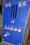
I really liked the booster pump for the heater. It and the heater fan had a dash override, so I'd run them after shutting down.
 

Attachments

  • Dash.jpg
    Dash.jpg
    231.5 KB · Views: 54
I used a DC pump mounted behind the radiator with a controller using a heat sensor fed into the head. I fitted a plate into the thermostat housing to act like a fully open thermostat. I also used a small DC booster pump to feed the heater circuit.
My setup wasn't successful! I had severe over-heating issues!

I've just realised my profile picture shows my car broken down, with these overheating issues, during an Owners club trip to Ireland!
Please offer more information. Why or how was it not successful? Thanks.

EDIT: Opps, I did not see your second post when I posted this reply. Thanks for the additional info.
 
Last edited:
The pump could be mounted up front, and an external thermostat housing used, but at first thought I think that'd require running an additional large hose up to the front of the car to enable a flow path during bypass operation. Definitely don't want all of the water going through the engine to have had to go through the radiator first, due to the engine coolant temperature gradient Karl and I mentioned above.


As far as my shift shift of mentality on the CWA pump to use... the CWA200 was better suited for me, but for the bit of extra money that a CWA400 costs, you get the same size package, vastly more performance, and likely nearly identical efficiency at low flow rates. Previously I was under the impression the impeller design is different, but as it seems to be the same, the efficiency should be similar.
I think with a E-pump that is electronically regulated (in lieu of a traditional T-stat), you would not need the bypass circuit. I would eliminate the stock T-stat and mount a block-off disk in its place. Then only two pipes run to the radiator (already existing). The basic layout would be the pipes connect to the stock T-stat housing as normal, with the pump somewhere in that loop. Then the original water pump is completely eliminated with a block-off plate and the coolant line from the T-stat housing connected to it. Or something to that effect.

I might be wrong, but from various prior posts I get the impression the CWA pumps are designed to be electronically controlled for engine temp regulation (e.g. the "tiny controller"). Therefore I'm guessing they should not have the issues others found with the DC pump when temperature controlled in place of a traditional T-stat.
 
Last edited:
I think it was the controller. It seemed to struggle adjusting the water flow. The pump seemed to run at full flow or no flow. My installation was 15 years ago, I'm sure that DC's new controllers work much better.
I really liked the booster pump for the heater. It and the heater fan had a dash override, so I'd run them after shutting down.
Sorry for the earlier post asking for more info, I missed the above response.

Someone else said a similar thing about the DC pump; it doesn't seem to do well at reduced speeds. So perhaps it might be in the design of the pump as well as the controller.
 
The pump could be mounted up front, and an external thermostat housing used, but at first thought I think that'd require running an additional large hose up to the front of the car to enable a flow path during bypass operation. Definitely don't want all of the water going through the engine to have had to go through the radiator first, due to the engine coolant temperature gradient Karl and I mentioned above.


As far as my shift shift of mentality on the CWA pump to use... the CWA200 was better suited for me, but for the bit of extra money that a CWA400 costs, you get the same size package, vastly more performance, and likely nearly identical efficiency at low flow rates. Previously I was under the impression the impeller design is different, but as it seems to be the same, the efficiency should be similar.
One could have the thermostat before the radiator with a bypass hose across the back of the radiator to the pump. This would give you effectively what the existing X system does and would take the thermostat off the back of the engine. Using the 124 type bypass thermostat for this would work well.

The first negative would be you would have much more coolant to warm up during startup mode. The second and to me bigger problem is the hysteresis in the system would increase the temperature variation of the engine as it overshoots the cooling need. Using the sensor for temp at the outlet of the head would reduce this but you would likely have a harder time managing it as the bypass thermostat would be reacting to slightly cooled coolant having run the length of the car and so on.

I see this as a solution looking for a problem.

As for reaching around the back of the engine to avoid the backside of the exhaust manifold, there is quite a bit of stuff around that side but the bigger issue is there isn’t much room between the engine and the sidewall for the tube to traverse to the back of the engine and you still have to get to the opening where the pump is. On an AC car the belts will pose an additional element to negotiate.

Personally I think the concern about heat gain from the manifold is minor and certainly could be minimized with insulation and shielding for the cross tube pipe to the header/exhaust manifold.

I think one could run the tube delivering coolant across the back firewall and make an adapter straight into the opening the water pump uses to access provide coolant into the engine. Basically come from the thermostat to the best arrangement of the pump, across the back of the engine bay and turn 90 degrees to run straight into the engine block. This works well until you think about an AC car which uses the water pump housing to to mount the alternator, this would need to be replicated. At this point the cross tube into the existing housing and it being capped off where the pulley was makes a ton of sense. It would be worth looking at this approach but I am thinking it will be more trouble than it is worth given the engine rocks front to back and the hose would need to deal with that over time.

Personally I don’t see using just the pump to regulate temp to be a reasonable solution. The pump is a crude means of controlling flow even with PWM, I am sure it could be managed but given that BMW and others still use some form of a thermostat in the face of being able to control all parts of the cooling process digitally, we aren’t there yet. Further, too slow of a flow rate will cause hot spots in the block/head as some areas flow better and will leave eddies of over heated coolant behind.

My view, worth what you are paying :) further, I have been wrong and will be again.
 
Well, I am going to post these pdfs that go through the whole cooling system saga for any vehicle. These are from another forum but they apply to any vehicle really. Well worth the read just for the general knowledge.
 

Attachments

  • Bill Vista Cooling Bible part 1.pdf
    3.6 MB · Views: 73
  • Bill Vista Cooling Bible part 2.pdf
    3.6 MB · Views: 58
  • Bill Vista Cooling Bible part 3.pdf
    2 MB · Views: 72
Back
Top