Dallara & K24: Recovering From OffRoad Experience

Worked a little this evening on the left headlamp aperture. Cut & bonded pieces of the targa for the under headlamp & marker surround areas. Once that is set, I can fibreglass the backside of the added pieces.

Inner upper radius will eventually match the outer

IMG-20200603-201755.jpg


For the inner side, I should be able to cut out the section of the vertical forward of the headlamp, and angle a new piece from the headlamp bezel to where I have the marker line

IMG-20200603-202421.jpg


IMG-20200603-202123.jpg


IMG-20200603-202306.jpg


Also painted the subframe section

IMG-20200603-202726.jpg
 
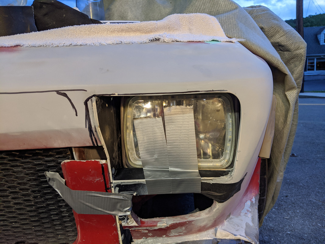
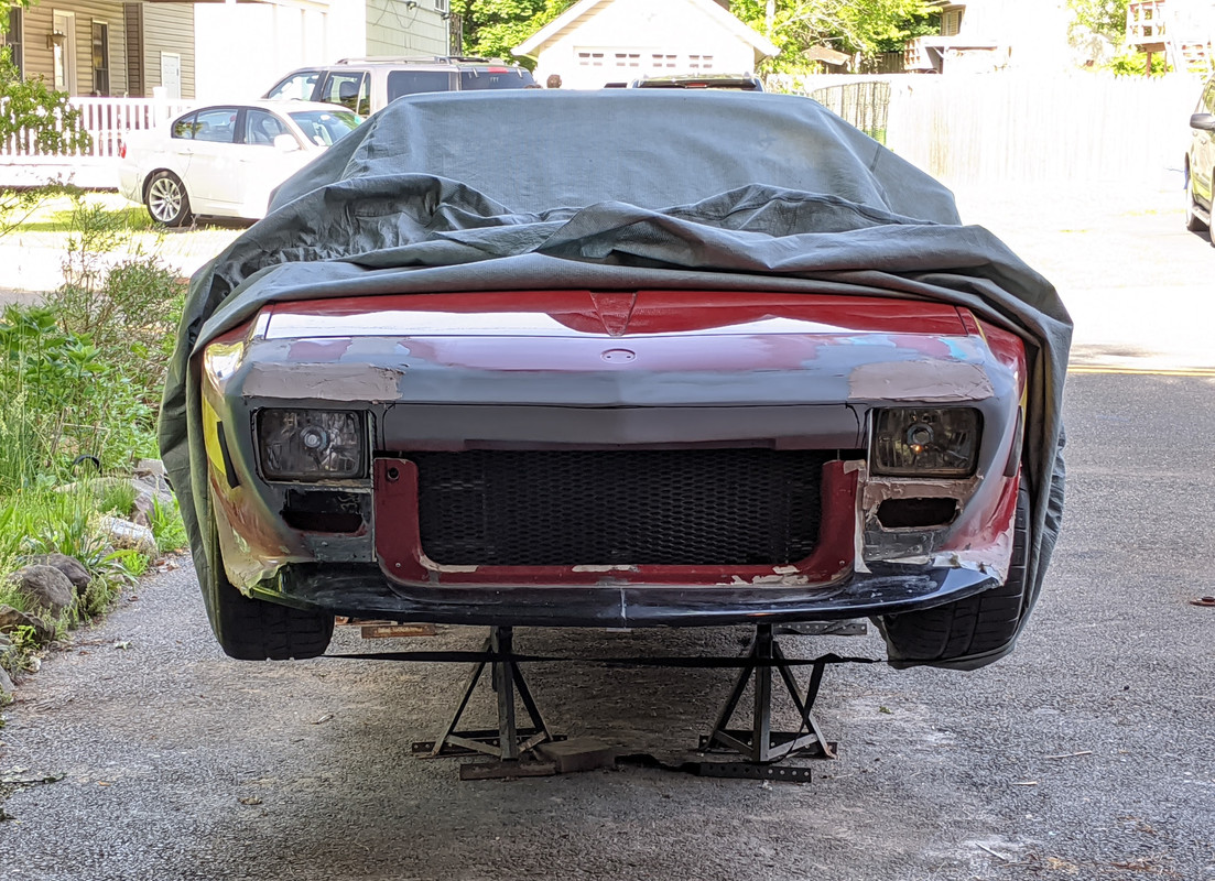
Got some work done on the nose today - focused on the tie-ins beneath the marker aperture to the vertical support, and an issue with the nose panel I didn't see until I looked at it in the mornign light. The headlamp cover contours were really soft still. Gonna be a few days before I get back to this - I'm going for foot surgery in the AM - inflamed ligament (due to or aggravated by bone spur) reduction in right heel. Will be nice to not be in pain anytime I stop moving :D

IMG-20200604-094937.jpg


So this afternoon after I did the tie-ins below the markers

IMG-20200604-211722.jpg


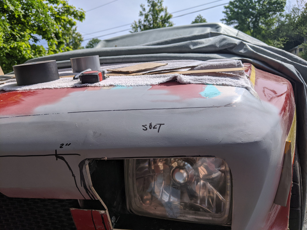
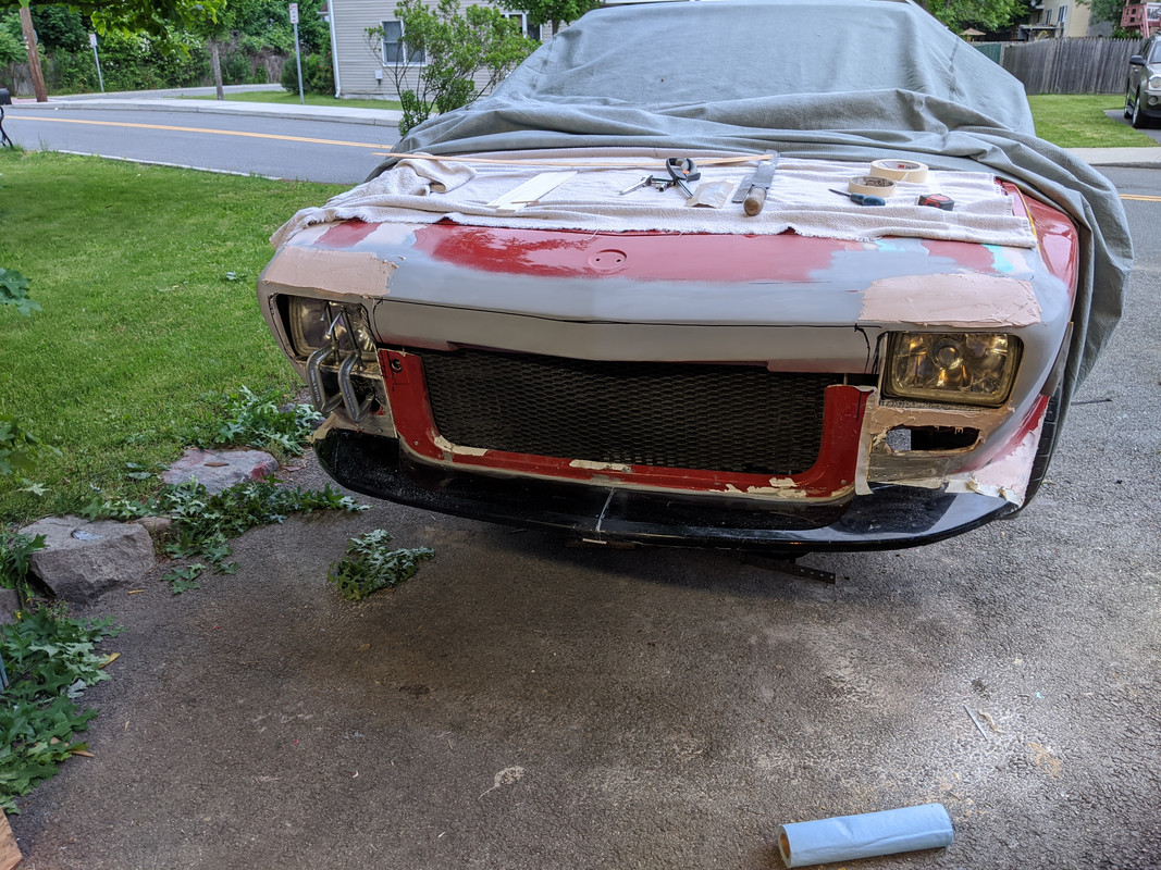
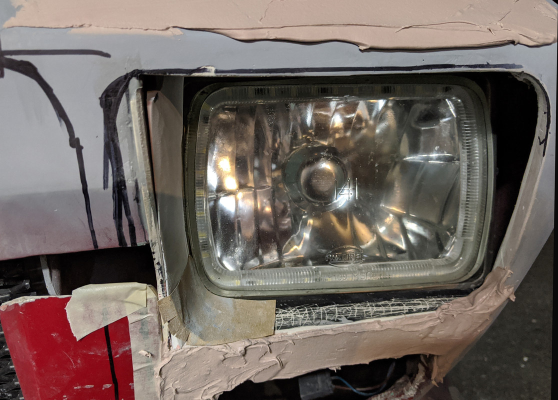
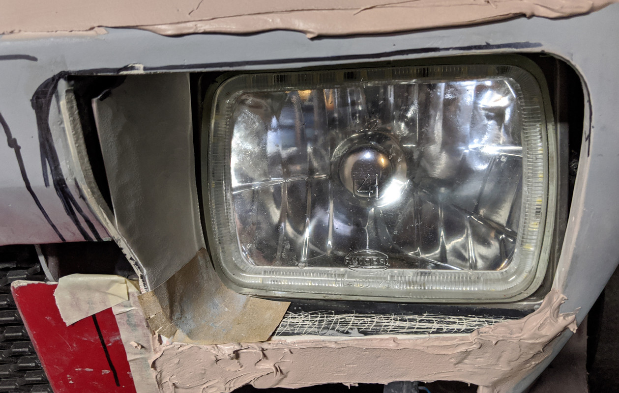
I added bondo to the headlamp cover areas, the ridge between leftside marker & headlamp, and to the fender skirts

IMG-20200604-200614.jpg


Also epoxied the right headlamp lower filler panel

IMG-20200604-200504.jpg


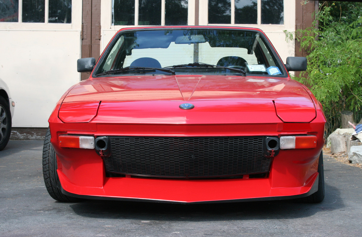
Stepping back and looking at it as a whole - I think I'll be happy with it. Need to get some primer on the spoiler so I can see it...

IMG-20200604-200554.jpg


IMG-20200608-170306.jpg


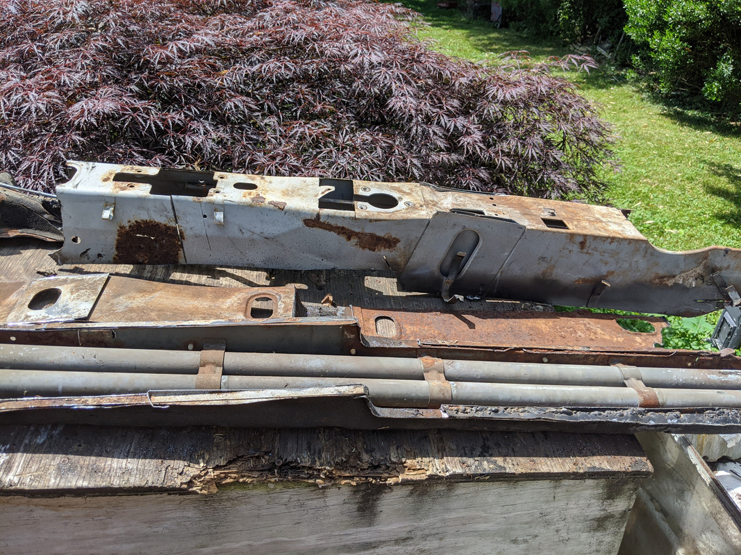
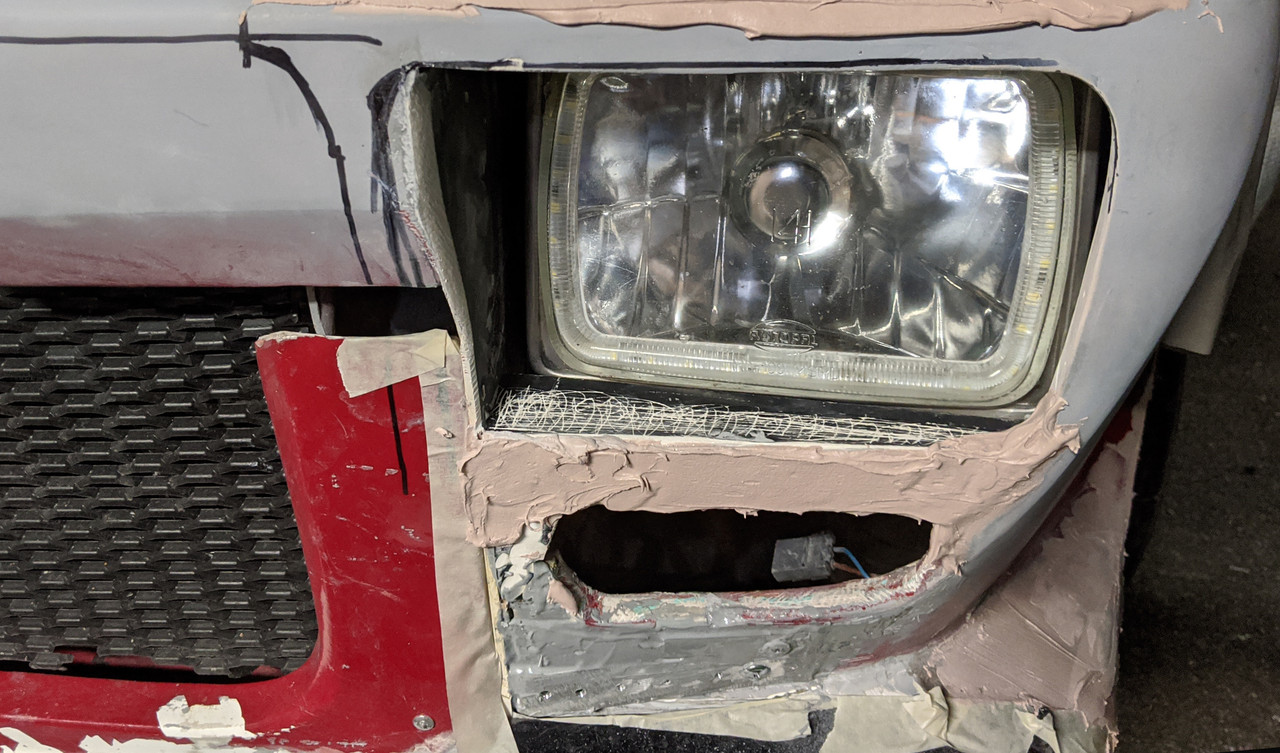
After some (much) thought - I am of the opinion that I can add a taper panel to the inner headlamp filler and round out the corners, without having to remove the vertical support panel - stuck a piece of sandpaper in there to illustrate the corner. That will remove the headache of what to do about securing the grille surround - which will have plastic rivets retaining it to the nose

The outer side opening looks exaggerated in this pic. There will also be a filler panel there.

IMG-20200604-210320.jpg


IMG-20200604-210326.jpg


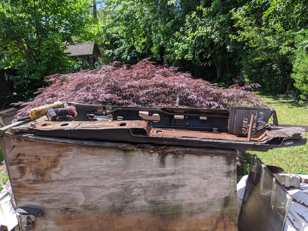
After I got done with all the attachments, I though again about what a PITA it is to work inside those fender/nose sections without an angle drive drill. I though about the fact that I had looked online at various corded/air versions - none of which are cheap - and completely forgot that I had bought a Milwaukee cordless M12 driver that matches my other M12 battery packs - I found it up on the shelf when I was cleaning up. Not sure I even need it anymore - all the awkward tie plates are in....
 
Last edited:
The more I look at the Dallara , mine as it stands, and the original nose, the more I feel I have to get that lip back across the center, even if it's only an 'accent'. Trying to figure out if I can use either my real router or my dremel with a router base to get a consistent depth/width undercut.

12063806-478690208958729-7701397636479919266-n.jpg


IMG-20200604-200504.jpg


X19-1069.jpg
 
Unless you are going to sharp cut the radiator opening to match I don’t think it would be the right thing to do.

Given your lower radiator grille, I would extend the inset you already have across the top and then extend the radiator grille upward to butt the underside of the inset or lap under.

That line is a carry over of the steel lip where the parts are welded, its fine on the production car but looks a little meh on the Jolly.

If you are going to hard cut the radiator opening completely like the Jolly car then yeah it makes sense, similar to your old spoiler.

If you do decide to go that way, don’t cut it so the opening is above the headlight openings (as you have it marked), keep the line in alignment with the top of the headlight openings. Having a consistent line across as opposed to a near miss will keep the design cohesive and related within the composition.

Thanks Karl - always good to have a voice of reason. Cutting a groove & getting it to flow into the nose vertical would be a royal pita, I'll leave that be.

I've left the vertical grille supports for now, as I have to devise an integrated attachment method for where they will bolt/clip to the upper center nose section. The plan is for some sort of lap joint, so the spoiler/grille can be pushed up into position and then clips inserted. I will probably paint all the clips in the spoiler/grille body color so as not to be a distraction .
 
I like the lap joint, the nose being proud of the element coming from below. You could have a flange going across the radiator opening that then mates to a horizontal surface behind the front to then attach to.

A00D655C-81E6-4590-A594-50096232086B.png
 
I like the lap joint, the nose being proud of the element coming from below. You could have a flange going across the radiator opening that then mates to a horizontal surface behind the front to then attach to.

I hadn't thought about adding a horizontal bar/flange across the bottom to use as the anchor point - I like that idea - doing so would take all the load off the uprights, so they can essentially just slot into place with maybe one clip per side to minimize rattle/movement.

EDIT: pic from underside - I already bonded an aluminum angle stock to the spoiler, so I can tie into that with a cross brace

IMG-20200608-170410.jpg
 
Last edited:
Couldn't take it anymore - basically sitting on my butt all day with my leg elevated - so I spent 25min & chopped out the center tunnel from the parts car with my sawsall. I did spend about an hour on my foot on Sunday, doing some yard work/hedge trimming, and that was definitely the limit.

IMG-20200618-152729.jpg


IMG-20200618-155931.jpg


IMG-20200618-155941.jpg


Not sure I wouldn't be better off making my own, it just won't look factory (not sure why I consider that an issue)...

IMG-20200618-160011.jpg


I'll strip it down at some point, from the top side to keep the flange intact.
 
Couldn't take it anymore - basically sitting on my butt all day with my leg elevated - so I spent 25min & chopped out the center tunnel from the parts car with my sawsall. I did spend about an hour on my foot on Sunday, doing some yard work/hedge trimming, and that was definitely the limit.

IMG-20200618-152729.jpg
Phew! You had me thinking for a minute it were some consequences of your off road experimentation...
 
If nothing else, you can practice making different coolant pipe covers without having to climb under your car and work upside down.
 
Coolant pipes arrived. I also ordered fresh Evans (have another gallon in the garage), as the sample test report from them came back:

"Water content is within specification. There is no contamination of oil, fuel or particulate matter. There is measurable mineral content and hardness, which suggests the water, while not excessive in volume, is hard. This is a concern with a largely aluminum system. Wear metals are minimal, but the pH has dropped and some degradation acids are evident. The corrosion inhibitor chemistry is starting to deplete. We feel this coolant should probably be replaced, as a best long-term solution"

Since this is essentially the same batch (since 2013) I've had through all the HG failures (just topped off with fresh each time) I figured might as well start from scratch :D

Only change I made was the shortened heater pipe for K2x install

IMG-20200619-102252.jpg
 
Glad to see my old car can help out in some fashion 😄- I'm sure you'll be able to figure something out even if it's just using the center section as a template!
 
Glad to see my old car can help out in some fashion 😄- I'm sure you'll be able to figure something out even if it's just using the center section as a template!

Yes, the parts car has be invaluable - besides some of the inner sheet metal, there are numerous odds & ends I have used off it at this point. I'm considering cutting out the frame sections where my swaybar ripped out, also.
 
Spent one hour outside on the tunnel. Doc said Friday I need to be careful for another week, or I will just prolong the heel recovery. Got the tunnel cut off the floor, and the floor cut off the pipe cover, main pipes removed. That's all I could manage. Judging from the sheer number of welds & reinforcements within the tunnel, it's really hard not to consider the three elements as integral to the rigidity of the car's structure. I don't think I'm going to weld whatever replacement I make though. Fusor epoxy or bolt-in with closed cell foam seal is the way I'm planning to proceed (as of right now).

IMG-20200622-104542.jpg


IMG-20200622-111016.jpg


Definitely not in the kind of condition I would want to attach to my car, no matter how carefully I prepped it. So, I'll use it as a template. Honestly, If I can get away with cutting off the forward section up to the center rise, and make a new cover for just that, I'd be satisfied. Question would be whether I can extract the old & then install the new without removing that rearward pipe hold-down
IMG-20200622-111942.jpg
 
Last edited:
Not a fan of foam in objects that get significant water driven into spaces.

Is this a structural closed cell foam that will never hold water?
 
Not a fan of foam in objects that get significant water driven into spaces.

Is this a structural closed cell foam that will never hold water?

The foam would only be in the event I bolt vs. bond the cover. Same thin closed cell foam I used for the trunk/bay panel & the spare well access panel - like this product
 
Did Abarth do anything different for the water pipe tunnel on the Prototipo?

I have no idea. Why would they? On that note, I've been thinking that the ideal X1/9 setup would be one essentially stock (when I say stock, I mean of course bumper delete, etc), one Dallara & one Prototipo. I really like mine, but now I do miss looking at the stock body lines also. And the Prototipo is just so cool. Unfortunately, I don't have the physical space to ever comtemplate such a scenario, plus my wife is adamant that one toy is enough. Since I enjoy living indoors (in harmony), I have to honor her wishes. I can dream though. :D
 
I would find it hard to believe you would have time to work on a second or third X in parallel with your current car.
I'm allowed two " silly" cars and I think a third if its in project status and no tags or insurance. At least that's my understanding.
 
Back
Top