
You are using an out of date browser. It may not display this or other websites correctly.
You should upgrade or use an alternative browser.
You should upgrade or use an alternative browser.
digital Gauge cluster
- Thread starter jrweikle
- Start date
Bob Brown coded up a demo for a digital based dash. I don't recall what it ran under ( around 2009, so Win7?), but I have a copy still. It has a Windows installer package for PC. I will see if I can find Bob's post from years ago. It will not install on Win10 or I would provide a screen shot. 
Update: The pictures are dead links, but here is the post.
I also found this one while searching.
Update: The pictures are dead links, but here is the post.
I also found this one while searching.
Last edited:
jrweikle
True Classic
bob browns the one i am thinking about
working on a dual lcd screen set up using pi zeros
pi zeros will be set to low power sleep mode to draw min power while the car is not running
still a ideal in progress
of course I am not a great programmer so we will se what it looks like when finished
working on a dual lcd screen set up using pi zeros
pi zeros will be set to low power sleep mode to draw min power while the car is not running
still a ideal in progress
of course I am not a great programmer so we will se what it looks like when finished
Dr.Jeff
True Classic
Here is the thread that's likely what I was remembering:
Electronic dashboard
Electronic dashboard. Found on Facebook. The guy is from France and got the kit cheap from China. You can see the result in the video
xwebforums.com

You need to talk to Bob, I don't think I should hand out his work.can i get a copy of that file?
No problem handing this out to anyone with an X1/9. :-D
Download HERE
Download HERE
The display is built up of Icons and Bitmaps in layers. The needles are vectors that have origin points and lengths, so I couldn't make those fancy. Had to do that to maintain speed, although with todays processors, you could rotate 1D images rather quickly. I wrote this about 15 years ago using Visual Basic v6.1. I bought a 12-channel data acquisition board that I was going to use as an interface for the gauges but never finished the project. Was doing too much travel at the time and couldn't find time to complete the project. I also bought 2 high brightness TFT displays to make up the display (couldn't find a single display that was bright enough at the time) and was going to split the display between the Tacho and the Speedo, but again, never finished it. Typical of a lot of projects I've started...
Last edited:
jrweikle
True Classic
would you be interested in giving me the code so I can update it to vb.net?
After updating it to VB.net it can be run on a raspberry pi thru Mono (.net for Linux) with little or no change and a Arduino can serve as the interface from the x to the PI computer
And I understand completely if you do not wish to give up the code but with that in mind would you mine me ripping off the image supplied by the Demo program?
Thanks
ng_randolph
Bjorn H
1000 revolutions of the speedometer cable is 1 km, so roughly 1609 revolutions pr mile. Assuming stock tire diameter.working on my idea to connect to my Raspberry pi working on the speedometer first
does anybody know if one revolution of the wheel = 1 revolution if the speedometer drive cable
my x is in a place right now that i cant test it out myself
jrweikle
True Classic
I have done some work on my digital gauge cluster....I have made a analog work stand so I can read the analog signals for the x....the program is wrote in visual basic net. And Bob I stole your display thanks.....I have the idiot lights actually working thru the raspberry pi I will be sending a video later when I get more of the electronics hooked up....I'm designing the speedometer adapter that use a hall effect sensor and will hook up to the pi


jrweikle
True Classic
this is the display i am getting
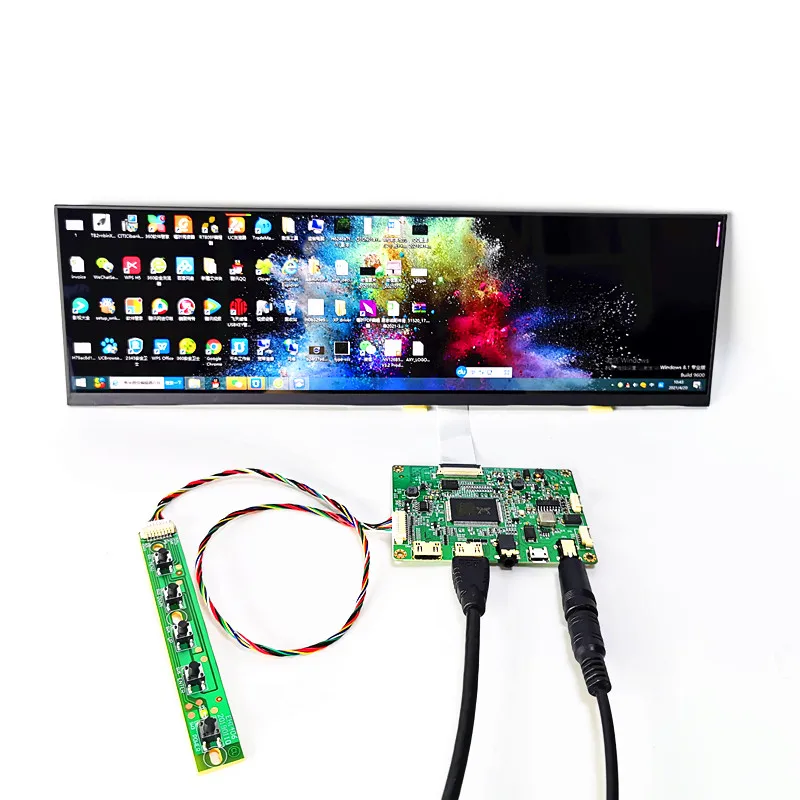
 www.aliexpress.com
56.64US $ 4% OFF|12.6-inch Bar Lcd Module Kit 1920*515 Hdmi-compatible Raspberry Pi Displays Computer Temperature Memory Car Lcd Display Diy Kit - Tablet Lcds & Panels - AliExpress
Smarter Shopping, Better Living! Aliexpress.com
jrweikle I hope you are able to get it working without a lengthy boot-up time.
10 + years ago when I wrote this code, the boot-up time was ridiculous so I shelved the project until I could get a faster computer.
I used a USB interface with analog & digital inputs (12 channel at the time) and was at the end stages of development, only the computer and display was sub-par. Time and technology has progressed, so I'm hoping you can have a working display READY in (say) 10 seconds after power-up.
Let me know how it goes!
darwoodious
Darin Nelson
Yes @bbrown - startup time on a Pi is still over 30 seconds. @jrweikle, maybe consider using a Sleepy Pi on your kit and have it sleep/hibernate when key off or out of the ignition and wake when you put key in/on.
Looks good tho. Keep us updated. I'm going another direction: classic cluster and convert the digital signals from a K20 swap to analog.
Looks good tho. Keep us updated. I'm going another direction: classic cluster and convert the digital signals from a K20 swap to analog.