
You are using an out of date browser. It may not display this or other websites correctly.
You should upgrade or use an alternative browser.
You should upgrade or use an alternative browser.
Electronics question
- Thread starter Dr.Jeff
- Start date
Dr.Jeff
True Classic
Here is the info given for the amp. As I said, it is a very inexpensive little board from China. Unfortunately this is all that's available on it:
2, monaural 18W amplifier circuit design
3,Onboard speaker docking station
4,Onboard 10K adjustable resistance, you can adjust the volume to enlarge
5,Onboard power indicator
6, the chip's main pin has been drawn, you can directly enter the audio signal
7, the working voltage: 6 ~ 12V
8, board size: 31.6 (mm) x23.2 (mm)

The "speaker" is described as to be used for a 12 V car alarm, which I thought would be good for this application - something of a alarm system. However there is no further information given for it at all.
Earlier I was thinking the amp was 14 watts, but I see it is 18 watts. And the voltage range is 6 to 12, while my power supply is actually 12.5 V. So I think the amp is getting enough power, and the output should be enough to drive a small speaker enough for my purposes. Therefore I believe you are right about the input not being enough. I don't think there is anything I can do about that? Keeping in mind I am not capable of reworking the circuit board in any way, that is simply way beyond my skills.
No question these are crappy components, but really just how much is needed for something like this.
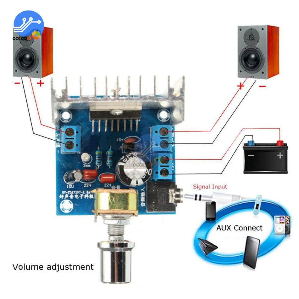
TDA2030 Amplifier Board Module
1, onboard TDA2030A audio amplifier chip2, monaural 18W amplifier circuit design
3,Onboard speaker docking station
4,Onboard 10K adjustable resistance, you can adjust the volume to enlarge
5,Onboard power indicator
6, the chip's main pin has been drawn, you can directly enter the audio signal
7, the working voltage: 6 ~ 12V
8, board size: 31.6 (mm) x23.2 (mm)
The "speaker" is described as to be used for a 12 V car alarm, which I thought would be good for this application - something of a alarm system. However there is no further information given for it at all.
Earlier I was thinking the amp was 14 watts, but I see it is 18 watts. And the voltage range is 6 to 12, while my power supply is actually 12.5 V. So I think the amp is getting enough power, and the output should be enough to drive a small speaker enough for my purposes. Therefore I believe you are right about the input not being enough. I don't think there is anything I can do about that? Keeping in mind I am not capable of reworking the circuit board in any way, that is simply way beyond my skills.
No question these are crappy components, but really just how much is needed for something like this.
Dr.Jeff
True Classic
My common sense tells me this won't work, but I have to ask.
Assuming the reason I'm not getting enough volume from my modified set up is the input signal (from the "receiver unit") isn't strong enough for the little amp I added on (as described earlier). Considering I purchased a couple of those little amps to play with, what will happen if I wire two of them end to end? Such that the signal from the "receiver unit" feeds into one amp, and the output from that amp feeds into the input of another amp; in other words use one of the amps as a pre-amp signal booster to feed another amp?
Assuming the reason I'm not getting enough volume from my modified set up is the input signal (from the "receiver unit") isn't strong enough for the little amp I added on (as described earlier). Considering I purchased a couple of those little amps to play with, what will happen if I wire two of them end to end? Such that the signal from the "receiver unit" feeds into one amp, and the output from that amp feeds into the input of another amp; in other words use one of the amps as a pre-amp signal booster to feed another amp?
Last edited:
dllubin
Don
I checked the IC they are using and it has more than enough gain (80dB) to amplify the signal. The question is how they configured it on the board. If you have a schematic, it could reveal something. Do you have the volume control turned all the way up? Most amps are designed to achieve full output with 1 to 1.5 volts in because that is what most audio sources supply.
Bjorn Nilson
True Classic
Don't do that. You will destroy at least one of the amps. First of all test the power amp with a line out or ear phone signal (from a stereo receiver or similar) that you know is working. You can also shorten the input on the amp to see if it makes noice on the speaker.Considering I purchased a couple of those little amps to play with, what will happen if I wire two of them end to end? Such that the signal from the "receiver unit" feeds into one amp, and the output from that amp feeds into the input of another amp
I have similar setup for my bedroom TV. It has no Line Out signal so I am using the head phone output to feed an external Dolby 2.0 device with subwoofer. If you can't have your amp working, buy a cheap external computer speaker. They work with almost any input impedance.
Dr.Jeff
True Classic
Believe it or not, I also looked up the data on the IC; that was something I learned from your past comments when I was attempting to build the fuel injector trigger device.I checked the IC they are using and it has more than enough gain (80dB) to amplify the signal. The question is how they configured it on the board. If you have a schematic, it could reveal something. Do you have the volume control turned all the way up? Most amps are designed to achieve full output with 1 to 1.5 volts in because that is what most audio sources supply.
 It seemed to look ok to me for what I wanted to do (well, at least as much of it that I understood).
Unfortunately there are no schematics that I can find for these amps.
Funny about the volume control. At first I assumed turning it clockwise would be full volume, like with every other electrical component I know of. So that's where I set it before the first test. No sound at all. Feared I'd installed it wrong, until I tried turning the control counter-clockwise. It's been on full volume ever since.
Dr.Jeff
True Classic
I figured it wouldn't work to connect two of the amps together. But the concept of adding a "pre-amp" might be a solution to the input being too low? I could look on AliExpress for a cheap pre-amp.Don't do that. You will destroy at least one of the amps. First of all test the power amp with a line out or ear phone signal (from a stereo receiver or similar) that you know is working. You can also shorten the input on the amp to see if it makes noice on the speaker.
I have similar setup for my bedroom TV. It has no Line Out signal so I am using the head phone output to feed an external Dolby 2.0 device with subwoofer. If you can't have your amp working, buy a cheap external computer speaker. They work with almost any input impedance.
I haven't tried connecting it to another source yet. Right now the connections are soldered on because I did not have the proper electrical connector to make it removable. So I'd have to unsolder the leads and add new ones. And if you understood my soldering skills then you would know why I'm reluctant to do that.

Not clear what you mean by "You can also shorten the input on the amp to see if it makes noice on the speaker" ?
I have some old computer speakers that I thought about using before buying the new siren ones. But they are not for outdoor use so I didn't try one. But I can to see what happens. I understand that would be without the external amp in use, but what about with the amp as well?
dllubin
Don
If you can find the feedback resistor on that board, you might be able to increase its value to bump up the gain. The data sheet I found had a typical applications circuit with it. That is probably not too far off what they are using on the board. You might try feeding the amp with a different device (cellphone, computer, radio ...) to determine how much input is required to get the desired sound level. Then, you can compare that to the output of your intended device to see how much extra gain to add.Believe it or not, I also looked up the data on the IC; that was something I learned from your past comments when I was attempting to build the fuel injector trigger device.
Unfortunately there are no schematics that I can find for these amps.
Funny about the volume control. At first I assumed turning it clockwise would be full volume, like with every other electrical component I know of. So that's where I set it before the first test. No sound at all. Feared I'd installed it wrong, until I tried turning the control counter-clockwise. It's been on full volume ever since.
Dr.Jeff
True Classic
What language is this?If you can find the feedback resistor on that board, you might be able to increase its value to bump up the gain.

I get the general idea of what you are saying, unfortunately it is well beyond my scope to do it though.
Although I haven't been able to actually measure or test the output and input values, based on what you guys have said I think it comes down to the fact the "receiver unit" doesn't have a strong enough output to give the add-on amp what it needs. With my limited abilities I doubt I'm going to be able to modify the receiver unit or the amp to change that. So perhaps my best approach might be to see if there is a small, simple, cheap pre-amp that can be added in between the two components. However that means another power source and more complexity to put everything together. But I'll take a look to see what's available. Otherwise finding a different speaker, driven directly from the receiver unit, that offers more volume (along the lines of what Bjorn suggested) is another approach.
Dr.Jeff
True Classic
Took a quick look on AliExpress for a preamp and saw this:
 www.aliexpress.com
But in the description it says something that caught my attention:
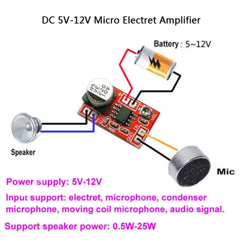
"Amplifier board IN and GND use shielded cable access electret microphone, access to the attention of the polarity, the electret after the reverse will be very little or no sound"
By my translation, it says if the polarity of the input leads is reversed, then you may get little or no output. Could this be possible on my existing setup? I would not think so, but can't say for sure. I'm assuming in the quoted description the polarity issue is only when a "electret microphone" is the input source?
1.52US $ 23% OFF|Dc 5v-12v Micro Electret Amplifier Mic Condenser Mini Microphone Amplifier Board - Operational Amplifier Chips - AliExpress
Smarter Shopping, Better Living! Aliexpress.com
But in the description it says something that caught my attention:
"Amplifier board IN and GND use shielded cable access electret microphone, access to the attention of the polarity, the electret after the reverse will be very little or no sound"
By my translation, it says if the polarity of the input leads is reversed, then you may get little or no output. Could this be possible on my existing setup? I would not think so, but can't say for sure. I'm assuming in the quoted description the polarity issue is only when a "electret microphone" is the input source?
dllubin
Don
Electret mics require power to operate (they have a built in preamp) and will only work with the correct polarity. I think that is what they are getting at. If this amp will work with electrets, which don't necessarily have huge output levels, it should work with your .7V signal. I am actually wondering if you might be overdriving it. Maybe try it with the volume control very low and see what it sounds like, then bring it up slowly.Took a quick look on AliExpress for a preamp and saw this:
1.52US $ 23% OFF|Dc 5v-12v Micro Electret Amplifier Mic Condenser Mini Microphone Amplifier Board - Operational Amplifier Chips - AliExpress
Smarter Shopping, Better Living! Aliexpress.com
But in the description it says something that caught my attention:
"Amplifier board IN and GND use shielded cable access electret microphone, access to the attention of the polarity, the electret after the reverse will be very little or no sound"
By my translation, it says if the polarity of the input leads is reversed, then you may get little or no output. Could this be possible on my existing setup? I would not think so, but can't say for sure. I'm assuming in the quoted description the polarity issue is only when a "electret microphone" is the input source?
Dr.Jeff
True Classic
I also found a couple of other preamps on AliExpress that may work for this. Here are a couple example just to show:
 www.aliexpress.com
 www.aliexpress.com
 www.aliexpress.com
And I also see a couple of amps that appear to include both a preamp and main amp:
 www.aliexpress.com
 www.aliexpress.com
I haven't sorted through them yet to see if any appear to be good candidates. But there seems to be a few ways to go with it.
3.56US $ 31% OFF|DC 5V 12V Micro Electret Amplifier MIC Condenser Mini Microphone Amplifier Board|Operational Amplifier Chips| - AliExpress
Smarter Shopping, Better Living! Aliexpress.com
0.86US $ 12% OFF|DC 3.8V 15V AD828 Stereo Dynamic Microphone Preamplifier Board MIC Preamp Module Amplifier Board|Integrated Circuits| - AliExpress
Smarter Shopping, Better Living! Aliexpress.com
1.68US $ |Wavgat Dc 3.8v-15v Ad828 Stereo Dynamic Microphone Preamplifier Board Mic Preamp Module Amplifier Board - Integrated Circuits - AliExpress
Smarter Shopping, Better Living! Aliexpress.com
And I also see a couple of amps that appear to include both a preamp and main amp:
4.27US $ 26% OFF|DC 12V TDA7379 38W+38W Stereo Amplifier Board with AD828 Preamp super than NE5532|Amplifier| - AliExpress
Smarter Shopping, Better Living! Aliexpress.com
1.65US $ 39% OFF|Tda7297 Version B Amplifier Board Dc 9-15v 15w*2 Digital Audio Power Amplifier Module Stereo Dual Channel 15w + 15w Amplificador - Operational Amplifier Chips - AliExpress
Smarter Shopping, Better Living! Aliexpress.com
I haven't sorted through them yet to see if any appear to be good candidates. But there seems to be a few ways to go with it.
Dr.Jeff
True Classic
That comment reminded me that the 'receiver unit' (as described in my first post) has a volume control. In the original configuration that increases or decreases the volume to the little onboard speaker. In the modified configuration it would control the signal level going into the add-on amp. This is one reason I thought I could connect the receiver directly to the amp, with the receiver acting similar to a preamp. I set the receiver's volume to the highest level before doing anything else (I'll double check to make sure it is still at max), but apparently that still isn't enough. However if I add a preamp between the receiver and the external amp, then that volume control on the receiver should allow me to lower the input to preamp if needed (i.e. it's being overdriven).I am actually wondering if you might be overdriving it. Maybe try it with the volume control very low and see what it sounds like, then bring it up slowly.
By the way, does anything standout with those little preamps I linked?
dllubin
Don
Before going to a preamp, I would connect a signal source (cellphone, radio, etc.) to what you already have and see if you are getting any reasonable output. I am a little suspicious that something is not right with the amp and/or speaker.
Another thing to try is capacitively coupling the input just in case it has a DC value that is screwing things up.
Another thing to try is capacitively coupling the input just in case it has a DC value that is screwing things up.
Dr.Jeff
True Classic
Yesterday I only had a minute to play with it, so wanted to make sure the receiver unit volume was still on max (it was). While doing that I decided to see if the output voltage (VAC) changed much at the three volume settings. With the signal only being short bursts (the "ding-dong" tone) it is difficult to get accurate readings. But at the highest volume level I'm still getting close to 1 VAC. Then I measured it at the amp output (not sure if that is a valid test) and got about 10 VAC. If I'm correct then I believe that means the amp is increasing the signal 10 times, and therefore must be working at least to some extent?
Dr.Jeff
True Classic
When I get more time I will try to perform some of the tests suggested.
Until then I came up with an idea that I don't know is valid. For the moment let's assume a preamp is needed. I reviewed the listings that I linked previously and narrowed the selection down to a couple. Which is where the new idea came in....one is mono and another is stereo.
Question: can I use a stereo preamp, wired from the "receiver unit" mono output to both sides/channels of the preamp input (i.e. a common ground and split the "+" lead to both the left and right stereo inputs), then wire the preamp output channels to two of the outboard amps (i.e. left preamp channel output to one amp and right preamp channel output to another amp)? This would allow me to have two speakers (one connected to each amp), that I can wire to different locations. With each speaker being supported by its own amp it should have the volume needed.
Previously I was going to build two of these modified 'receiver units' with external amps, each supplying a speaker in a different location. This way I only need to modify one receiver unit, but still be able to locate two speakers. What I don't know is if the mono source signal can be split like that into the stereo preamp? I'm sure the source signal's strength will be lowered, but hopefully the preamp/amp combo will be strong enough to work with that. Afterall we were concerned the receiver unit's signal may be too strong for these preamps.
Alternatively, another possibility is to scrap the external amps I currently have and buy one with a preamp and main amp together on one circuit board. By using a stereo amp I could locate each of the two speakers (left and right) in the desired locations. However the same question exists; can the mono source signal from the receiver unit be split to feed both channels on a stereo preamp/amp board?
dllubin
Don
The gain of 10 sounds like it is in the range of what you would expect. It looks like the resistors are accessible and mostly marked in value. The feedback resistor could be replaced with a higher value which would increase the gain. That resistor is normally connected to the output and the inverting input. If you wanted twice the gain, you could double the value of the feedback resistor.