Eurosport body, K20 power

I'm also converting from a siphon tube to the bottom feed valve. I think that will make the biggest difference. I just bought a cyclone from China pretty cheap. Previously I've had my cabinet set up as pressurized to blow the dust out and through a water trap filter. But the surrounding room air still gets full of dust. I think the pressurized cabinet allows too much escape from elsewhere beyond the exit port to the filter. Hopefully changing to a vacuum system with the cyclone will work better.
 
Still waiting for the media blaster - it has been wet here so he is backed up with work waiting on the weather. Also waiting for the machine shop to hone/bore the K20Z1 block and do up the head. While waiting I decided to go ahead and fit the engine - I have a spare K20A2 and trans to use for this (will be sold after I have the Z1 built).

Here I have fit and welded up the subframe:
Subframe.jpg

This went well, there was some minor clearancing to do for the small bolts.

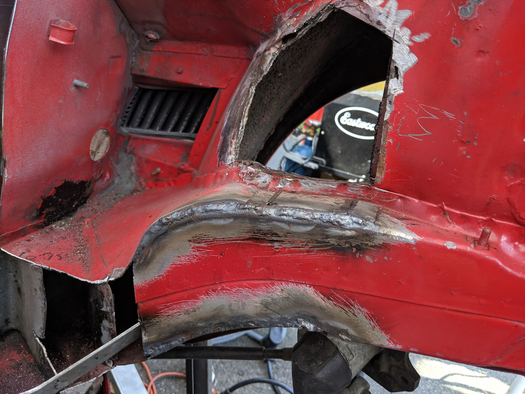
Front frame and firewall cut:
Front cut.jpg


Left cut, side view:
Left cut final side vewi.jpg


Left cut again, from bottom:
Left cut final bottom view.jpg


I thought I was cutting minimal amounts, but on the left cut the rear portion of the initial cut still had about an inch more clearance than required:

Left cut excess.jpg


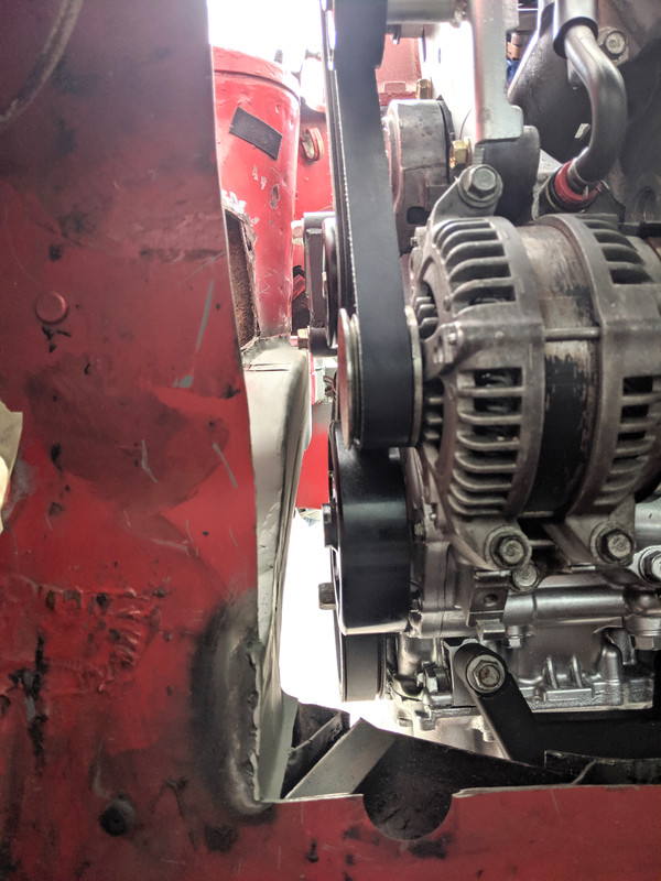
On the right side I did an initial small cut but the clearance for the water pump pulley was paper thin - it turned freely but who wants to pull the motor to change the belt........:
Initial right cut Water pump clearance.jpg


So I cut some more - here is the final right cut from the side:
Right cut final side view.jpg


And here is the right cut from the bottom - I was able to bend that bumper frame extension enough so the filler piece will clear it:
Right cut final bottom view.jpg


And now the water pump pulley has reasonable clearance:
Right cut final water pump clearance.jpg


Engine in place, ready to fit the torque suppression mount:
Engine in place.jpg


When I initially fit the torque suppression mount the bottom of the arm was hitting the frame rail...... so I notched the frame rail a bit. When I went to tack the mount to the frame rail it was a little lower than some of the pictures I had seen (by ~1/8"). I then remembered a post discussing taking some of the weight off the engine before tacking the mount in position. So I lifted the right rear corner a wee bit with my floor jack. The mount came into position, and now the arm was well clear of the frame rail as well. So now I had to fill the notch I had taken out - thus as you can see in the pic below one corner of the mount got a bit more heat.

Mount welded in position:
Welded top mount.jpg


I have 2 intake manifolds, a PRB and an RBC. I wanted to use the RBC but the runners are too long and the manifold tilts up too high, so I will stick with the PRB.

Intake in place:
Intake clearance.jpg


Intake top view - angle for tube clearance:
Intake tube angle.jpg


This is without the tube adapter thickness and the firewall insulation accounted for. I still might massage the firewall bulge a little for more clearance, will wait till the fuel tank is in place to see how much room there is. I am also cognizant of the need to be able to get the bolts into the flange, I recall reading Roger's account of this issue.

Next I will fab up the firewall enclosure and it's door.
 

Attachments

  • Initial right cut Water pump clearance.jpg
    Initial right cut Water pump clearance.jpg
    288.1 KB · Views: 118
  • Firewall cut final.jpg
    Firewall cut final.jpg
    365.2 KB · Views: 108
  • Firewall cut final.jpg
    Firewall cut final.jpg
    365.2 KB · Views: 116
Coming along! Just noting the variations in your frame mods. I didn't need to cut the right skin back as much to get clearance off the pulley. Your frame kit is quite different than the version I have - curious if it's an older gen?
 
I don't know for sure the frame kit is, I got it from Brett a couple years ago off this forum, along with the body kit.
 
I spoke with Brett from Molalla, Oregon that was an early Midwest bayless kit, (I was wishing to be able to aford that setup and start my own K20, but can't justify the money or the time right now.)
 
Been puzzing over the variation in depth of frame cut required for yours. This is mine:

IMG-20190819-085538.jpg


narrow pie cut tapered towards rear & welded outer skin back in place. Forward edge is similar depth to yours, based on corner of cross rail cover overlap of for/aft rail

IMG-20190812-160240.jpg


On the right, I made a smaller cutout than yours:

IMG-20190818-162042.jpg


Clearance is good on the inside - on the outside (inner fender/strut tower) the skin needs to be pushed out to clear that centrally located (in pic) boss & web

IMG_20190818_162100.jpg


I'm wondering if the diffferences are all due to the subframe kit - perhaps your version set the drivetrain 1/2"-3/4" further to the right, I think that would explain it.
 
I suspect you are correct, and there is a difference in the kit. Here is a picture of the left side clearance - I did not have to massage the outer skin and have ~1/4" clearance there.

IMG_20200707_061127.jpg
 
"You've go to know when to hold em, know when to fold em, know when to walk away, and know when to run........" (Kenny Rogers - The Gambler)

The blaster came and did his thing yesterday and today, and what was revealed was not nice at all - let me show you:

Floor pan, left:
Floor pan drivers side.jpg


Floor pan, right:
Floor pan passenger side.jpg


Frunk, left:
Frunk divers side .jpg


Frunk, right:
Frunk Psgr side.jpg


Spare tire well:
Spare tire well.jpg


Windshield frame, left side:
Windshield frame drivers side.jpg


Left outer frame rail from bottom:
Left outer frame rail from bottom.jpg


Left outer frame rail from inside cab:
Left outer frame rail from inside .jpg


Right outer frame rail:

Right outer frame rail.jpg


Left side, bottom of door pillar:
Left side bottoom of door pillar.jpg


Right side middle crossmember:
Middle crossmember right side.jpg


Rear crossmember left side:
Rear crossmember left side.jpg


Rear crossmember from right end:
Rear crossmember right end.jpg


So far, while pretty extensive, I believe this is all repairable. However the worst is yet to come.......

While inspecting the results from the media blasting it became obvious there was a lot of brazing that had been done on the left front inner fender area, and a fair bit of crumpling had occurred and been subsequently somewhat straightened. This car had experienced a significant hit on the left front. There was an area by the steering rack outlet where the metal had folded and not been repaired, and may not be reasonably repairable. A measurement between the fore and aft front suspension points revealed a half inch difference side to side. Here are a few pics of this:

Left side measures 18 3/8:
Crink Left side 18 3 8ths.jpg


Right side measure 18 7/8:
Crink Right side 18 7 8ths.jpg


Left side cross brace under steering rack, note the profile:
Crink Left side.jpg


And the right side, same spot, this is what the profile should be:
Crink Right side.jpg


So with all that, as Mr. Rogers says, I think it is time to walk away. To repair this would be a major undertaking. The entire front end would have to come off.

I will have a look for another body to use, but will probably need to go State side, and that won't happen until the travel restrictions are removed.

BAH!
 
"You've go to know when to hold em, know when to fold em, know when to walk away, and know when to run........" (Kenny Rogers - The Gambler)

The blaster came and did his thing yesterday and today, and what was revealed was not nice at all - let me show you:


So with all that, as Mr. Rogers says, I think it is time to walk away. To repair this would be a major undertaking. The entire front end would have to come off.

I will have a look for another body to use, but will probably need to go State side, and that won't happen until the travel restrictions are removed.

BAH!

Dang. Makes my heart sink as I scroll down through all the pics. Would have been quite a daunting task to work over the ENTIRE chassis fixing all that perforation. The crumpled left front - that must have wreaked havoc with alignments - it's hard to see how they could possibly have compensated for that much push-back on the left?

There's no way you could talk to a frame shop about trying to pull it back, or is the perforation just so extensive that it would just shred at all the seams?

Very sad indeed if that is the case.
 
That certainly sucks. While most of that rust seems rather common for these cars, and anything is repairable, yours does seem quite a lot in total. Some of those areas look like they've already been replaced/patched previously. Add the collision damage (also not uncommon unfortunately), and I'd have to agree finding a better condition candidate may be best. That's assuming the replacement chassis is actually better. We've seen a lot of similar looking X's on the forum, and initially they often look much better than they really are (as you found out). But there are still goods ones to be found. ;)
 
“or is the perforation just so extensive that it would just shred at all the seams?”

I think this is the issue with trying to pull the areas that are distorted, many areas of the car are so weak that the areas which have been distorted would stay distorted and find the weak points tearing them open and further distorting the rest of the chassis.

Definitely not fun. At first I was oh the floor boards are a little worse than usual and then it was, oh my.

Sorry.
 
As you say, pulling it would just pull the car apart. The only way to fix this would be to dismantle the entire front section up to the frunk "firewall", straighten/replace and then put it back together. Could be done but very time consuming, especially without a jig of some sort. I would be tempted to try it if the rest of the car was in reasonable condition but the combination is just too much for me. This is a setback, but I will eventually find another body to use for this project and carry on.
 
Finding another body didn't take as long as I expected. My son found this one in Medicine Hat, Alberta and we made the journey Monday (8 hours travel each way) and brought it home. Appears to be in much better condition, not perfect but what do you expect for $700 Cdn?

77 X19.jpg


Dropped the engine out today:
IMG_20200723_194002.jpg


Was quite surprised to see the insulation/SS in the muffler well fully intact.
 
I will watch with great interest, Mark. I like watching the "ground-up" builds. And BTW, I wish I could get some of these X's floating around here to you guys in "rust-belts". If you can find an X that lived it's life from Sacramento down to Mexico, and east through Utah, you will likely find a car with very little rust. We sometimes take it for granted here. But seeing Mark's last swiss-cheese mobile makes me sad. I will always keep my eye open for a clean X. Needed or not.
 
Last edited:
Thanks for the details and the pictures of your project. Posts like this give inspiration to those of us that are just starting out. I look forward to future status updates.
 
I seem to recall reading somewhere that the X19 wheelbase is different for European cars versus North American cars. Is that correct? The reason I ask is that the front wheels do not sit centered in the wheel well. I noticed this when fitting the body kit to the '74 as well. I can fix this by cutting a piece out of the bumper and reshaping the wheel well on the fender portion, but I wonder if there is another fix available.

Wheel well.jpg
 
Back
Top