
You are using an out of date browser. It may not display this or other websites correctly.
You should upgrade or use an alternative browser.
You should upgrade or use an alternative browser.
Front end shake
- Thread starter TonyK
- Start date
LarryC
Curator of #10105275
Update: I did the 65 mph drive and I an surprised and pleased to report that the steering wheel shake is much abated with new front hoses. Looks like culprit in at least this scenario. No more pull to the right either. So brake drag coupled with a little rotor run-out.
TonyK
True Classic
Ordered bushings from Vic's and having sent to Bob Martin's in Kentucky as I will be there at the end of this month. Shipping $12 USD. Looked on UK sites but price was about double for what appeared to be the same part.
As for someone else working on my car...not going to happen.
TonyK.
Grimsby Ontario Canada.
As for someone else working on my car...not going to happen.
TonyK.
Grimsby Ontario Canada.
PaulD
Paul Davock
Ordered bushings from Vic's and having sent to Bob Martin's in Kentucky as I will be there at the end of this month. Shipping $12 USD. Looked on UK sites but price was about double for what appeared to be the same part.
As for someone else working on my car...not going to happen.
TonyK.
Grimsby Ontario Canada.
To do it yourself, you can check out Smart Racing products. They sell a smart level camber gauge (not cheap) which will work well without leveling the car. They also sell a castor adjusting fitting, only you can make guides for how far to turn the wheel for multiple camber measurements and some math that will give you a castor reading.
Paul D.
ArtBasement
Erwin Timmers
The differing number of washers cause the different thread lengths you saw at the end of the radius rods.Keep track of the washers and their placement as that is the means of adjusting caster.
TonyK
True Classic
Interesting set up and not complicated for me to fabricate. I did not see what was being used for Castor, could you tell me where to look for it.To do it yourself, you can check out Smart Racing products. They sell a smart level camber gauge (not cheap) which will work well without leveling the car. They also sell a castor adjusting fitting, only you can make guides for how far to turn the wheel for multiple camber measurements and some math that will give you a castor reading.
Paul D.
Thanks.
TonyK.
Grimsby Ontario Canada
kmead
Old enough to know better
I would get one of these or a similar means of measuring camber angle. A bubble camber gauge would work fine.
https://www.amazon.com/dp/B006JR8XB...t=&hvlocphy=9017530&hvtargid=pla-313284583886
You will need two turn plates which allow the tire to turn left to right easily without binding on the floor. They are marked with degrees to understand the angle turned.
There is a reasonable amount of discussion here: http://www.pro-touring.com/threads/75589-checking-caster-angle I am sure there are other better directions one could find.
From that thread:
So yes you can do it without taking it to someone else...
https://www.amazon.com/dp/B006JR8XB...t=&hvlocphy=9017530&hvtargid=pla-313284583886
You will need two turn plates which allow the tire to turn left to right easily without binding on the floor. They are marked with degrees to understand the angle turned.
There is a reasonable amount of discussion here: http://www.pro-touring.com/threads/75589-checking-caster-angle I am sure there are other better directions one could find.
From that thread:
Turn the front of the tire your 20 degrees inboard first and take your angle reading (if you were doing the RF, then turn the tire like you are making a left turn), then turn the front of the wheel outboard the 20 degrees and take the second angle measurement.
If when turning the front of the tire inboard (for first measurement), the tire/wheel goes more negative (inboard at the top) and then goes more positive (outboard at the top) when you swing the tire out for the second measurement, you have positive caster.
Like was stated, add the total amount of angle change by 1.5 and you will have your caster reading. Put slightly more caster on the right side (1/4 to 1/2 degree) to help the car track straighter on a crowned road, or make the measurements the same for a track car.
So yes you can do it without taking it to someone else...
Dan Sarandrea (Phila)
Waitin' On Parts...
Ordered bushings from Vic's and having sent to Bob Martin's in Kentucky as I will be there at the end of this month. Shipping $12 USD. Looked on UK sites but price was about double for what appeared to be the same part.
As for someone else working on my car...not going to happen.
TonyK.
Grimsby Ontario Canada.
There's no shame in having others work on your car if the job at hand requires specialized tooling or equipment.
For example, you could refinish cylinder walls with a drill and a $50 ball hone, but yeah the machine shop with the $150,000 Sunnen CNC SV-25 automatic hone is gonna yield a better end result.
Same could be said for having suspension geometry checked at a shop with state-of-the-art alignment equipment and (probably more importantly) trained operators.
Rupunzell
Bernice Loui
The common automotive alignment shop with computer aided wheel alignment systems have an inherent and designed in problem for accuracy. The optical or similar wheel sensors are mounted to the wheel's rim. This attachment is inherently fully of accuracy problems due to the wheel rim to sensor attachment, condition of the rim and actual contact surfaces involved. This why no serious race teams will used them for high accuracy, high precision suspension alignment. These wheel alignment systems are designed to produce fast accurate enough results with the focus of reducing operator time required to set up wheel alignment on a vehicle.
To gain high accuracy and precision, the moto sports folks resort to hub-wheel stands with string and the better speciality system have load cells built into these wheel-hub stands to measure corner weight. Wheel-hub stands takes the inherent problems with attaching the sensor to the wheel out of the wheel alignment process greatly improving accuracy and precision. The modern angle sensor is more than accurate enough for measuring camber and castor.
Essentially, the "low tech" string alignment set up can be remarkably accurate and precise if properly applied and using a digital level with zero degree offset capability is good enough to measure camber and castor.
Bernice
There's no shame in having others work on your car if the job at hand requires specialized tooling or equipment.
Same could be said for having suspension geometry checked at a shop with state-of-the-art alignment equipment and (probably more importantly) trained operators.
Rupunzell
Bernice Loui
Large stability bar (anti-roll bar) end bushings can be used for the radius rod bushings they are essentially much the same and can be had in urethane if desired. These are lower cost and not difficult to get. Take one of the original bushings measure or visually compare them to the target stability bar coupler bushing for a reasonable match, then install.
Bernice
Bernice
Ordered bushings from Vic's and having sent to Bob Martin's in Kentucky as I will be there at the end of this month. Shipping $12 USD. Looked on UK sites but price was about double for what appeared to be the same part.
As for someone else working on my car...not going to happen.
TonyK.
Grimsby Ontario Canada.
PaulD
Paul Davock
Interesting set up and not complicated for me to fabricate. I did not see what was being used for Castor, could you tell me where to look for it.
Thanks.
TonyK.
Grimsby Ontario Canada
Instructions are here:
http://smartracingproducts.com/smartcamber/SmartCamber Instructions_2014_final_update.pdf
Starting on page 8
Paul
TonyK
True Classic
Thanks Bernice, I never thought of sway bar bushings like from a pick up truck. If made from Urethane they can be turned in the Lathe to size.Large stability bar (anti-roll bar) end bushings can be used for the radius rod bushings they are essentially much the same and can be had in urethane if desired. These are lower cost and not difficult to get. Take one of the original bushings measure or visually compare them to the target stability bar coupler bushing for a reasonable match, then install.
Bernice
TonyK.
Grimsby Ontario Canada.
Paul Valente
Automotive Engineer
With the current optical systems (since the late 90's), you roll the car backwards and forwards and it calculates the axis of rotation of the wheel. It doesn't matter if the rim is bent or not it still rotates about the same centerline. The machine calculates toe and camber off of the axis of rotaion, not the rim.
http://www.freepatentsonline.com/5535522.pdf
One could read the whole patent if you want but the relavent parts are:
Column 5 line 1 to 4
Column 8 line 12 to 35
Oh...and this one is prior art:
http://www.freepatentsonline.com/4180915.pdf
http://www.freepatentsonline.com/5535522.pdf
One could read the whole patent if you want but the relavent parts are:
Column 5 line 1 to 4
Column 8 line 12 to 35
Oh...and this one is prior art:
http://www.freepatentsonline.com/4180915.pdf
Last edited:
Rupunzell
Bernice Loui
What happens to wheel data point acquisition when:
*The center axis of the reflector is not directly in line with the wheel axis?
*Defective or damaged reflector element on the wheel sensor?
*Optical projection and camera out of alignment/calibration?
*The tire/wheel is not round causing vertical movement of the acquired data points when the vehicle is rolled?
*The surface is not smooth causing vertical movement of the acquired data points when the vehicle is rolled (like rolling over the turn plates of a typical alignment rack) ?
*If the vehicle is steered during rolling data point acquisition?
Bernice
With the current optical systems (since the late 90's), you roll the car backwards and forwards and it calculates the axis of rotation of the wheel. It doesn't matter if the rim is bent or not it still rotates about the same centerline. The machine calculates toe and camber off of the axis of rotaion, not the rim.
http://www.freepatentsonline.com/5535522.pdf
One could read the whole patent if you want but the relavent parts are:
Column 5 line 1 to 4
Column 8 line 12 to 35
Oh...and this one:
http://www.freepatentsonline.com/4180915.pdf
Paul Valente
Automotive Engineer
What happens to wheel data point acquisition when:
*The center axis of the reflector is not directly in line with the wheel axis?
There is no center axis of the reflector. It is just a flat panel. The reflector is firmly attached to the wheel and rotates with it about the wheel's axis.
*Defective or damaged reflector element on the wheel sensor?
A tool aficianado such as yourself would not expect a broken or miscalibrated tool to work, would they?
*Optical projection and camera out of alignment/calibration?
Again, do you expect a broken tool to work? How could you expect a resonable torque reading from a torque wrench that is out of calibration?
*The tire/wheel is not round causing vertical movement of the acquired data points when the vehicle is rolled?
The algorithm calculates the axis of rotation. It doesn't matter if the wheel is round or has runout. It rotates about the same axis regardless. The math is in the bodies of the two referenced patents.
*The surface is not smooth causing vertical movement of the acquired data points when the vehicle is rolled (like rolling over the turn plates of a typical alignment rack) ?
It is looking at the angular position of the targets. They can move up or down to some degree and still be accurate. If it moves so much that it would be in error, the machine will ask you to start over and re-roll the car.
*If the vehicle is steered during rolling data point acquisition?
It can tell that the axis has rotated about the kingpin axis and will ask that you re-roll the car.
Hey I don't sell these things, but I have used them when we were working on suspension modules. Some of the statements you made lead me to believe that perhaps people were not aware of the principles of these machines so I thought I'd point out how they worked. If you care to learn about them, I would hope that you would read the references. At least the "Summary of Invention" parts. You will find that there are people that have thought about these questions already and have documented it.
IMHO it is far superior to any method where you are measuring from the tire or rim precisely because of the reasons you point out, the tire and rim have run-out and roundness issues whereas the axis of rotation does not.
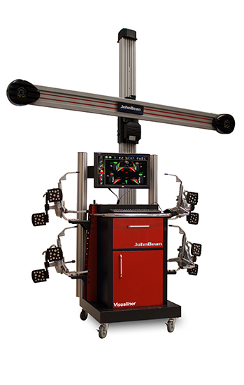
Just to clairify, the machines I'm talking about and that the patents reference basically look like this one...
*The center axis of the reflector is not directly in line with the wheel axis?
There is no center axis of the reflector. It is just a flat panel. The reflector is firmly attached to the wheel and rotates with it about the wheel's axis.
*Defective or damaged reflector element on the wheel sensor?
A tool aficianado such as yourself would not expect a broken or miscalibrated tool to work, would they?
*Optical projection and camera out of alignment/calibration?
Again, do you expect a broken tool to work? How could you expect a resonable torque reading from a torque wrench that is out of calibration?
*The tire/wheel is not round causing vertical movement of the acquired data points when the vehicle is rolled?
The algorithm calculates the axis of rotation. It doesn't matter if the wheel is round or has runout. It rotates about the same axis regardless. The math is in the bodies of the two referenced patents.
*The surface is not smooth causing vertical movement of the acquired data points when the vehicle is rolled (like rolling over the turn plates of a typical alignment rack) ?
It is looking at the angular position of the targets. They can move up or down to some degree and still be accurate. If it moves so much that it would be in error, the machine will ask you to start over and re-roll the car.
*If the vehicle is steered during rolling data point acquisition?
It can tell that the axis has rotated about the kingpin axis and will ask that you re-roll the car.
Hey I don't sell these things, but I have used them when we were working on suspension modules. Some of the statements you made lead me to believe that perhaps people were not aware of the principles of these machines so I thought I'd point out how they worked. If you care to learn about them, I would hope that you would read the references. At least the "Summary of Invention" parts. You will find that there are people that have thought about these questions already and have documented it.
IMHO it is far superior to any method where you are measuring from the tire or rim precisely because of the reasons you point out, the tire and rim have run-out and roundness issues whereas the axis of rotation does not.
Just to clairify, the machines I'm talking about and that the patents reference basically look like this one...
Last edited:
Rupunzell
Bernice Loui
Service-operatiors manual like this alignment machine:
http://www.snaponequipment.com/common/productmanuals/wa/teewa546p4/teewa546p4.pdf
Resulting in this patent:
https://www.google.com/patents/US20160273914
Not a fan of software compensated measurement system without knowing precisely how and what they are compensating for. Similar to modeling and simulations where the models and simulation software is creator dependent.
Point being, if these optical alignment system are that superior, why are so many race teams still using string, wheel-hub stands? These optical system can work well, but as with all measurement systems, they have limitations. Knowing what they are is significant.
Bernice
Paul Valente
Automotive Engineer
It may be that the teams feel that they want one system of measurement be it at the track or in the shop. The visual ones aren't very portable so taking them to the track rules them out. I'm not saying the hub mounted systems are inferior; they take the wheel and tire out of the measurement so they are as accurate as the operator cares to be. The techniques that are suspect are the ones where one is measuring off of the wheel/tire without any sort of compensation for run-out...and I guess my original point (and the only point I really care to make) is that the modern visual systems do compensate for run-out.
*FYI that link you shared is actually still an application. The patent office requires that applications be made public after 18 months if it hasn't yet issued. Reading the proposed claims it seems pretty broad to me at this point (the lawyers always try to get as broad coverage as possible and I'm not a lawyer). They are basically claiming, you roll the car, you measure the wheel assembly while it is rolling, you do a calculation and then if there is a deviated value you select an action. I suspect the examiner will ask them to get more specific.
*FYI that link you shared is actually still an application. The patent office requires that applications be made public after 18 months if it hasn't yet issued. Reading the proposed claims it seems pretty broad to me at this point (the lawyers always try to get as broad coverage as possible and I'm not a lawyer). They are basically claiming, you roll the car, you measure the wheel assembly while it is rolling, you do a calculation and then if there is a deviated value you select an action. I suspect the examiner will ask them to get more specific.
Rupunzell
Bernice Loui
For race folks portability does matter. These modern optical alignment system tend to be bulky due to their complexity and set up (stand, camera-illumiation system and more) complexity and space required. The modern system DO compensate do run out after folks who make these began to address inherent sources or error in these systems.
In the electronic instrumentation world, this technique that is being used on these optical alignment systems is known as Normalization. Have been using instrumentation with this feature since the early 1980's. It works and can improve accuracy if the sensor and input data points is completely predictable and repeatable. Problem with this method, tolerances in the real world tend to limit the amount of accuracy enhancement possible unless the user/designer(s) are extremely careful of all possible variables.
My first exposure to these optical wheel alignment systems were in the mid-1990's when a company asked me to design (consulting job) a high power LED driver for them. Turns out this company who asked for the design to be done was used in the first generation Snap-On optical alignment system. Got a proto demo and a pretty good idea of how these systems work including the machine vision software-hardware.
Do not think or believe I'm totally negative or un-accepting of these optical wheel alignment systems, they are a compromise for vehicle production and vehicle service environments where speed, ease of use and enough accuracy is a must. The racer folk's portable alignment system with hub-wheel stands, string, load cells at each wheel is difficult to set up and the users MUST know precisely and exactly what they are doing or there will be a disaster. When done properly, these alignment systems are remarkably accurate and precise and repeatable trading off ease of use-set up, reduction of possible user errors and many other real world factors that would make the racer's rig nearly impossible to be effective in the shop or production vehicle environment.
Bernice
Last edited:
Rupunzell
Bernice Loui
MK technologies, one of some who makes these wheel/hub stand/string chassis_suspension alignment systems.
http://www.mktechnologies.com/whats_new/whats_new.htm
VelocityHass:
http://velocityhaus.com/set-up-tools/set-up-wheels-gt-cars.html
Some of the major teams build their own for a specific car with load cells like this:
https://www.novatechloadcells.co.uk/ds/set.htm
Made these some years ago. They are height adjustable using a screw to allow setting the stand to loaded tire-wheel height with precision, rolls on precision PTFE lined spherical bearings to allow for angular movement of the suspension as adjustments are made. Stainless steel sheet on top of the corner weight pad reduces roller to pad friction. Entire set up can be taken to the track allowing suspension and chassis set up as needed on location with enough accuracy, precision and repeatability.
Pretty much what the majority of racer folks do and it works quite well.

Bernice
http://www.mktechnologies.com/whats_new/whats_new.htm
VelocityHass:
http://velocityhaus.com/set-up-tools/set-up-wheels-gt-cars.html
Some of the major teams build their own for a specific car with load cells like this:
https://www.novatechloadcells.co.uk/ds/set.htm
Made these some years ago. They are height adjustable using a screw to allow setting the stand to loaded tire-wheel height with precision, rolls on precision PTFE lined spherical bearings to allow for angular movement of the suspension as adjustments are made. Stainless steel sheet on top of the corner weight pad reduces roller to pad friction. Entire set up can be taken to the track allowing suspension and chassis set up as needed on location with enough accuracy, precision and repeatability.
Pretty much what the majority of racer folks do and it works quite well.
Bernice
Last edited:
Simon Oaten
Daily Driver
string, level surface, and digital inclinometer, and a couple of bits of ally ......
cost - 100
http://imexlasers.com.au/product/imex-160mm-digital-level/
can set up car just abt anywhere .....
setup time - 5min's
Bernice - do those scales have a "hold function" ????
rgds
simon
cost - 100
http://imexlasers.com.au/product/imex-160mm-digital-level/
can set up car just abt anywhere .....
setup time - 5min's
Bernice - do those scales have a "hold function" ????
rgds
simon