Has anyone done a custom manifold?

I was planning to build some custom tubular manifolds for both turbo and NA applications. The starting point was to get some proper flanges made. Here is the thread on that:
https://xwebforums.com/forum/index.php?threads/manifold-flanges.32715/
As you can see that thread died without success so the project has stalled.

Not totally stalled, I'm waiting on some more time to work on it, like so many on here time is the limiting factor. I will restart this project sometime this spring, maybe sooner if I can find some free time for sale somewhere...
 
Here is one I prototyped for a friends car a few years ago, A FD RX7 with a 20B engine.
Number 1.JPG

IMG_5922.JPG

unfortunately this project stalled and is still sitting like this. this is just a thin wall mock up, the final will be .120" wall 318 stainless.
 
Well done Brian, nice looking design. I love how you are able to develop it in CAD first.

One possible difficulty in making a "equal-length high-flow" turbo header design for the X's engine is the location of the exhaust ports (relative to one another on the head). In the various examples of twisted-tube type (either in my earlier post or the one Brian developed), they are for engines that have equal distances between all of the exhaust ports. This allows the header to be designed with equal length tubes more easily. The X's head has exhaust ports that are not equal distant; the middle two (#2 and 3) are next to each other and the outer two (#1 and 4) are further apart to allow the intake manifold to fit in between. This makes it more difficult to get all four tubes equal length with very short runs (close to the head, where you want the turbo to be). Also it must be arranged to place the turbo well within the engine bay; so the extremely high heat from it does not cause issues, the inlet/outlet compressor piping can be routed for good efficiency, there are no clearance problems, etc.. Making a equal length header is not as difficult to do for a long tube design (i.e. non-turbo application), but with a turbo there are many more considerations. I'm not saying it can't be done, just that it requires more thought and likely more compromise in the design. Perhaps this is one reason the "log" design works well, as it allows for easier placement of everything with a much simpler design. I'd really like to learn how much difference these two types make in terms of turbo efficiency/performance.

From what I learned from the engine builder on that project, at least for a rotary engine but I don't think it would be very different for a piston engine, having the exhaust pulses evenly timed does give it a small advantage but it was his belief that it wasn't enough of an advantage to make it worth the effort to get equal length tubes. His theory was to get each tube to flow smoothly from flange to turbo and that was good enough, much better than a log style manifold. In the case of the RX7 space was at a premium, he wanted a 4" down pipe and a 2" waste gate pipe and both of those had to merge at the back of the engine bay into a 3" pipe out the back so space was the main factor in deciding on equal length of unequal length. (Disclaimer: I have never had a turbo so everything I just said is based on what I was told by the engine builder on that project.)
 
Brian, that sounds about what I would think also. For a turbo application the small advantage of pulse balancing may not be practical to achieve in many cases due to other constraints. But overall good flow should be a goal.

I wonder just how much the total flow differs between a individual runner/merged design and some of the smoother "log" designs (one example below)...where the smooth, gentle bends flow directly into a wide open turbo flange (unless this is not what you meant by "log", it can differ like I mentioned in my prior post). But I'm certainly not a flow dynamic specialist so no idea.

download.jpg
 
Well done Brian, nice looking design. I love how you are able to develop it in CAD first.

That worked well, I had made up some standard bends and could make any I needed on the fly in a matter of minutes. so when it came time to cut the material I could just click on that bend and get the degrees of bend and the clocking information, then I made a jig that the bend clamped to with a protractor on it each bend had a line drawn down the center line on the outside of the bend for clocking, just set the protractor to the degrees needed and run it into the vertical bandsaw then I had a small 360 degree protractor to mark the degrees of clocking from the center line we drew on it and tack it in place. Had to make a few minor adjustments which could be noted on the cad for future reference.
IMG_20180111_131940951.jpg
IMG_20180111_131954531.jpg
 
Brian, that sounds about what I would think also. For a turbo application the small advantage of pulse balancing may not be practical to achieve in many cases due to other constraints. But overall good flow should be a goal.

I wonder just how much the total flow differs between a individual runner/merged design and some of the smoother "log" designs (one example below)...where the smooth, gentle bends flow directly into a wide open turbo flange (unless this is not what you meant by "log", it can differ like I mentioned in my prior post). But I'm certainly not a flow dynamic specialist so no idea.

View attachment 7598
The one you pictured I wouldn't call it a log as each runner ends at the flange, they may be short but they don't really share the log.

This is more what I consider a log style.
images.logmanifold.jpg
 
Nice jig for cutting curved tube sections. There is a tool/equipment company that specializes in fabrication aids with a similar jig for the same purpose. Yours does every thing it does without the cost.
Tube angle fixture 2.jpg Tube angle fixture 3.JPG


This is more what I consider a log style.
Regarding a "log" manifold. I think we are showing our age; that last picture you posted is what I would call a "log" manifold also. But if you search Google Image for "turbo log manifold" all you see are ones like the last picture I posted. So the definition seems to have changed since we used it.

As I mentioned earlier, the old style "log" as we knew it (your last picture) was actually considered a better design for turbos at one point. "Breaking up" the flow or something. Clearly I don't think that is considered true any longer. I would guess the newer style "log" (like in my last picture) might work well; decent flow, good strength, easy to "package" the layout, good heat tolerance, and not difficult to make (those sections come pre-made, for the most part you just weld them together).
 
Nice jig for cutting curved tube sections. There is a tool/equipment company that specializes in fabrication aids with a similar jig for the same purpose. Yours does every thing it does without the cost.
View attachment 7613 View attachment 7614


Regarding a "log" manifold. I think we are showing our age; that last picture you posted is what I would call a "log" manifold also. But if you search Google Image for "turbo log manifold" all you see are ones like the last picture I posted. So the definition seems to have changed since we used it.

As I mentioned earlier, the old style "log" as we knew it (your last picture) was actually considered a better design for turbos at one point. "Breaking up" the flow or something. Clearly I don't think that is considered true any longer. I would guess the newer style "log" (like in my last picture) might work well; decent flow, good strength, easy to "package" the layout, good heat tolerance, and not difficult to make (those sections come pre-made, for the most part you just weld them together).

Showing Age.... remember the old log intake manifolds for the flatheads where you would just keep adding more 2 bbl carbs....
 
Some difficulties with building a proposed "log" turbo exhaust manifold for the X1/9. In this case I'm referring to the modern "log" style as in the examples by "lanchiahf" and "stingray250", earlier in this thread. However their examples were not for the X1/9, and this makes a difference (as we'll see).

I am not a turbo expert by any means, and have no experience building this particular type manifold. So this is merely some thoughts on what might need to be considered when building one for a X1/9.

If we start with the pre-made "els" (as noted by Simon), using common sizes, the closest to the X's port diameter is 1.25", however the actual ID is closer to 1.38" depending on material and thickness (gauge). Not an ideal size but it could work.

We could use two "Elbow"s (90*) for the ends of the log, and two "T"s for the middle section...as in the prior examples:
download (1).jpg
Something like this, but as we will see the arrangement will differ for the X.

The "T"s in that size have a total width of 1.75" (according to one manufacturer's chart). That means when you weld two of them together, you end up with a center to center distance of 1.75" for the ports:
images.jpg
.875 X 2 = 1.75

The "Elbow"s are 1.25" from the port center-line to the end of the bend (where it will join the middle sections):
download (2).jpg
1.25" (elbow) + .875" (one half of a T) = 2.125"


Looking at the X's head / port design, the center two (#2 and #3) are close together, and the outer two (#1 and #4) are spaced out further:
download.jpg
images (1).jpg


If the distance between #2 and #3 is closer than 1.75" (I have not measured to see), then some material could be trimmed off the "T"s ends to bring them closer.
It appears the gaps between [#1 and #2], and [#3 and #4] are greater than 2.125" (again, I have not measured), so additional material will need to be added to join them at the correct distances apart.
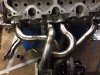
Welding these pieces together and onto a manifold flange (similar shape as the pictured manifold gasket above) completes the "log" portion. Something like this:

images (4).jpg


Placement of the turbo's flange is the next decision. It can be joined to the log with a beveled section of larger tube:
images.jpg
images (2).jpg


In most cases it seems the best flow is achieved by locating the turbo in the center of the log, between cylinders #2 and #3. However that might not be ideal on the X1/9, due to the center two ports being so close together. This gives an almost straight shot from ports #2 and #3 into the turbo flange, but a considerably longer run (and around a 90* turn) for ports #1 and #4. I do not know how much this matters.

The turbo could be located off-set to either side of the middle two ports, but this biases the run from the outer two ports. That is how the cast iron manifold for the Uno Turbo is made, mainly to re-position the turbo for packaging reasons on that particular application I believe. I'm not sure if this is any better than the centered layout above. Uno Turbo cast iron manifold:
s-l225.jpg

Another design option is something of a part "new style log" and part "old style log". This might be necessary if the two center ports are too close together to allow use of two "T"s. Here #2 and #3 are simple straight runners hitting the main log head on, which is also a compromise in flow:

images (3).jpg


This discussion is merely a starting point. Hopefully someone can offer further input about the ideas suggested here; the good and bad points of various options and any fabrication considerations to making a manifold like this.
 
Last edited:
Looks good. Miata? How long have you run that manifold, and any signs of cracking, etc? I'm just trying to gauge my options. Thanks

Chevy 2.4 Ecotec... This one (below) was for my 2.2 Ecotec in my 72' VW... No problems thus far... It makes it really easy if you get a piece of 2x2-1/8" angle and lay the fittings in the "V" of the angle iron then tack em together... Nice and straight... I had to trim mine down and oblong the fittings @ the ports to match the flange/head.

DSC01282.JPG DSC01152.JPG
 
Also, be aware, no matter how hard you try unless you have the fittings/manifold tig welded, the flange will want to pull up at the ends and will require a little bit of resurfacing to get a proper seal against the head... Being that mine was made of regular carbon steel, you can imagine how hot it got during the welding process! :) I had to resurface about 0.040" off of it to get it all flat again.
 
here is a pipe chart that shows the different sizes and wall thicknesses for the different schedules.

pipe chart.JPG

The stock port size I just measured is roughly 1.1" so the best fit may be 1.25" SCH 80 which would give an ID of 1.278" and a wall thickness of 0.191" which would leave about .090" step from the port to the manifold flange. it would allow for some port matching and some porting. if more porting is wanted then step down to SCH 40 for an ID of 1.380".

Then there is tubing sizes.

tubing chart.JPG

which gives some more ID choices, however weld el's are not as available for tubing sizes as they are for pipe sizes so get out your compromise calculator...

I've been thinking of using 1 3/8" 16 gauge for my NA header, might want something heavier for a turbo manifold like the 1 1/4" above.

I think I will be working towards a tubing header with a merge collector if I try to turbo a 1500 as I believe that would be more efficient.
 
I'd love to see what you can come up with in your CAD software.

Stick around, I have the flange modeled just need to model the head, block and engine compartment clearances on the back side of the engine. That's what I did on the RX7.

I did finally get a printer big enough to print out the flange to do the final adjusting.

My biggest problem is I promised the better half that we would move into the new house this spring, somehow the car projects don't get much time right now. lol.
 
somehow the car projects don't get much time right now.
I understand. I have not been able to make any real progress on my projects either for similar reasons.

If you get a chance please send me a copy of the file or a print out for the flange. I'd like to play with some optional intake and exhaust manifold ideas and don't have your computer skills to do it virtually. So I'll play with some cheap materials to make concept models. I can message you my email if you prefer. Thanks.
 
Thanks for the reference. I've looked at a couple others (but don't recall seeing this one). One thing I've noticed is most of the turbo "design" resources are very dated. And turbo technology has come a LONG way. The only 'current' info I've found is internet stuff that I'm not sure is accurate (you know how that is). I'll take a closer look at your reference.
 
imho - its "the" best techo reference ive come across ......

search the online SAE papers:

old mazda paper excerpts"
https://www.rx7club.com/single-turb...s-single-scroll-vs-twin-scroll-turbos-903210/

MHI:

several (incld gamma-ta material)
http://www.mhi.co.jp/technology/review/pdf/e501/e501023.pdf

ditto BorgWarner (see amg turbo's)

ditto garrett....

the "advantages" are not just abt pulse tuning - but more abt the pressures across the cylinder - and what that means as far as reqd cam timing and cylinder fill....

rgds
simon
 

Attachments

  • IMG_4570.JPG
    IMG_4570.JPG
    388.6 KB · Views: 93
Thanks, lots of cool info Simon, I'll read through it as I have time.

In my case I'll likely start out just using the factory Uno Turbo (UT) cast iron exhaust manifold and the factory UT turbo. I realize that both are compromised designs but that is what I already have available. And I want to get the basic system built and running before I go too far with developing better components...which I plan to do eventually. I'm sure there will be plenty of learning to do as I progress (this will be my first experience with a turbo system). So I appreciate the input.
 
Back
Top