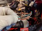
Inexpensive headlight relay kit from Amazon

The circled plug replaces the old headlight

(you remove the plug from the stock headlight, and plug this plug into that socket. then the two orange plugs in your picture plug onto the headlights.
Ah, ok. Does it matter which one, driver’s or passenger?
 
In each headlight pod there is a 3 position connector that plugs into the back of the headlight. You will unplug both of these three position connectors. The plug circled in yellow above will plug into one of the connectors you just unplugged. Either one, your choice; whichever is the most convenient for cable routing. The one you don't use won't plug into anything.
 
Last edited:
I have had my hands on three different types of LED sealed beam replacements, and they all used the same pinout as the incandescent sealed beam units they were meant to replace. If you have conventional sealed beam units now, and you are replacing them with LED "sealed beam" units, you'll need a harness wired for sealed beam headlights.

Disconnect the battery negative before you work in the headlight pods. The headlight motors are powerful and geared for torque; you wouldn't want limbs caught in anything if the motors decide to run.

LED units tend to be a bit bigger than conventional sealed beam units. Before reconnecting the battery, run each headlight through a complete up / down cycle manually by turning the knob at the back of the motor. Make sure nothing catches as the pods go up and down. The motors always run in the same direction (i.e. not one direction for "up" and the other direction for "down"). Just keep turning the knob in the same direction until you've gone through a complete cycle.
 
Last edited:
After looking this over, and looking over the 74’s wiring pods, my question is: where is the single, power connection on the exxe that the circled connector goes to - is it a combination of wires hitting one of the factory relays, because if there’s a single, master, headlight connector, I haven’t found it. In their description it’s called the “vehicle headlamp socket”, or the “vehicle wiring harness”. Guessing I still won’t get any assistance from Mo.? ;)

View attachment 55641
This goes into the existing headlight connector to provide the control signal to the two relays. The headlight sockets are both the same. This connector can go into either headlight socket connector either left or right and control the two relays.
 
I have had my hands on three different types of LED sealed beam replacements, and they all used the same pinout as the incandescent sealed beam units they were meant to replace. If you have conventional sealed beam units now, and you are replacing them with LED "sealed beam" units, you'll need a harness wired for sealed beam headlights.

Disconnect the battery negative before you work in the headlight pods. The headlight motors are powerful and geared for torque; you wouldn't want limbs caught in anything if the motors decide to run.

LED units tend to be a bit bigger than conventional sealed beam units. Before reconnecting the battery, run each headlight through a complete up / down cycle manually by turning the knob at the back of the motor. Make sure nothing catches as the pods go up and down. The motors always run in the same direction (i.e. not one direction for "up" and the other direction for "down"). Just keep turning the knob in the same direction until you've gone through a complete cycle.
After blowing a few fuses and bulbs in my early days with the car, I installed a quick-off, negative battery terminal for ANYTHING electrical. It gets a lot of use :) It’s pretty tight in those pods, so manual testing is a very good idea
 
I have had my hands on three different types of LED sealed beam replacements, and they all used the same pinout as the incandescent sealed beam units they were meant to replace. If you have conventional sealed beam units now, and you are replacing them with LED "sealed beam" units, you'll need a harness wired for sealed beam headlights.

Disconnect the battery negative before you work in the headlight pods. The headlight motors are powerful and geared for torque; you wouldn't want limbs caught in anything if the motors decide to run.

LED units tend to be a bit bigger than conventional sealed beam units. Before reconnecting the battery, run each headlight through a complete up / down cycle manually by turning the knob at the back of the motor. Make sure nothing catches as the pods go up and down. The motors always run in the same direction (i.e. not one direction for "up" and the other direction for "down"). Just keep turning the knob in the same direction until you've gone through a complete cycle.
What's your thinking on maximum distance a fuse should be from the battery? Most articles say 18" (457mm lol), but these kits seem to cut the fuse wire close to the relays, which most people position in the headlight pods. Is the main concern that a longer fuse wire may get clipped/cut by accident, as opposed to any operational/safety advantage?
 
Last edited:
What's your thinking on maximum distance a fuse should be from the battery? Most articles say 18" (457mm lol), but these kits seem to cut the fuse wire close to the relays, which most people position in the headlight pods. Is the main concern that a longer fuse wire may get clipped/cut by accident, as opposed to any operational/safety advantage?
You want the fuse near the battery so if there is a failure in the wire, the short will blow the fuse rather than burn the car down.

This would be particularly true of a solution where there is a relatively long distance from the battery to the point of use.
 
Like in this case. I guess it's easy enough to do some wire editing...it really would be better to have a much longer wire leading to the fuse holder, for cars like ours where the battery is no where near the headlights. I suppose that’s an easy fix.
 
Last edited:
I have been working my way through upgrading the lighting on my 85X. This past week I installed LEDs in the tail lights, front and rear turn signals and reverse lights. I put the proper LED flasher in the relay tray. Somehow, I forgot to order the marker LEDs and license plate LEDs. I will get the markers, but I think I may leave the license bulbs stock. The recommended LED didn't fit very well in the housing.

Today, I finally got around to installing the headlight relay kit I got off Amazon for about $20.00USD. I decided to try the Amazon set, since I had used a similar Ebay set on the 124 Special a few years ago. The kit is not as well made as Bob's kits, and some wires needed to be extended or have their terminators snipped and swapped for something more appropriate.

Anywho... It took me a few hours to work thru the process. I put the relays in the passenger side pod, because there were easily accessible wire grommets to use for routing the power wire to the battery. I ran a 10ga wire from the battery into the pod and attached it to the kit's power wire that had a 30a fuse holder installed. My 85 had two little dimples stamped in the pod ahead of the position where the ground blossom is installed. I drilled the forwardmost dimple and bolted the relay set inside the pod.
View attachment 47454 View attachment 47455

There was plenty of wire between the two head light connectors to reach between the headlight pods. I did have to remove the kit's headlight connector for the "remote" headlight in order to get the wires thru the grommets in the pods. I zip tied the headlight wires to the stock loom that passes between the pods. Horrible picture, I should have taken a picture when the car was in the air. The thicker and cleaner blue and white wires towards the top of the picture are the high/low beam wires running from the relay set to the driver side headlight.
View attachment 47457

The biggest concern I had was the headlight connectors themselves. The X has 90 degree wire connectors to provide a little wiggle room. The kit's connectors are not 90s and I was a little worried that I wouldn't be able to get them on without pulling the headlights. I managed to carefully get them on, but then I was worried the wires would rub on the headlight bucket or the pod's cross support in operation. Thankfully it all worked out and none of the wires is rubbing. You can see there is some clearance between the bucket and the wires on the connector. I will probably go back through and see if there are places that might benefit from another zip tie or two for wire management.

Driver side:View attachment 47453 Passenger side:View attachment 47458

Prior to all this light upgrading, my volt meter would drop significantly when the headlights were on, or brakes were applied. It would swing up and down with the blinkers. If it rained, I just left the wipers off. Try any combination of the above and the volt meter would bottom out. I took a test drive this evening after finishing up and now the voltmeter barely moves no matter which lights I turn on. I am sure the blinkers would still make the VM unhappy, but that is a task for another time.

As I was leaving the garage, I noticed there are lots of open hoods and engine covers. Lots of little tasks to take care of on each car.
View attachment 47460
When you say "I ran a 10ga wire from the battery into the pod and attached it to the kit's power wire that had a 30a fuse holder installed...", did you just cut off the supplied connector and butt them together?
And did you relocate the fuse closer to the battery, outside the headlight pod?
What gauge wire do you figure was attached by the manufacturer which was feeding that fuse, 16 gauge?
 
I'm interested in the original poster and how he cut the wire...
Either make a new one with new connectors or cut it and put in as many inline permanent connections as needed with an insulation applied.

As you are looking to use a fuse box rather than the inline fuse, a single new wire run to there the inline fuse was with a an inline connector would be the thing to do.

Here is an image of a proper connection on a light gauge wire created by Hussien before he added insulation:

D6490030-0051-4C52-BA10-29097A7D5BAC.jpeg
 
Either make a new one with new connectors or cut it and put in as many inline permanent connections as needed with an insulation applied.

As you are looking to use a fuse box rather than the inline fuse, a single new wire run to there the inline fuse was with a an inline connector would be the thing to do.

Here is an image of a proper connection on a light gauge wire created by Hussien before he added insulation:

View attachment 55889
Thanks. I’m sorry you’re the one who has to answer this :) I ’may’ use that fuse box, but I’m also weighing NEG’s use of interlocking fuse holders, which does reduce space requirements. I have both a positive and negative busbar that can be utilized as well.
 
Thanks. I’m sorry you’re the one who has to answer this :) I ’may’ use that fuse box, but I’m also weighing NEG’s use of interlocking fuse holders, which does reduce space requirements. I have both a positive and negative busbar that can be utilized as well.
Do you mean interlocking relay holders with integral fuses?

Personally I like having the run protected by the fuse versus a fuse protecting the short distance to the point of use with a long unprotected run but the biggest factor is just ensuring it is protected and the right gauge of wire is used to deliver the amperage needed to run the item efficiently.

We all have our predilections.
Agreed. That’s why I’d change the fuse wire if the headlight relays are in the pod.
 
Back
Top