Hey Rodger. Thanks for the kind words.
Yes, Rodger and I have been working on this project on and off for a couple of years now. It started when his X was gutted and in the body shop. My chosen rear donor bar required brackets for the mounting bushes to be either welded or bolted to the rear lower chassis member. For his car we decided on weld on. Nice and strong and neat. I made some up and shipped them to him. He had the body shop weld them in. Super strong, and after they were painted along with the rest of the underside, it looked like they were there from the factory. After that, everything else could just be bolted in. Worst case scenario, he could always use the brackets to support something needed for his K20 conversion, or at the very least he now had some nifty new jacking points.
As his project progressed and he got the rear suspension back in, we worked some more on the fitting details. Luckily, Rodger - like me - is rather fussy, and likes to do things right. And is a really smart guy. Together we explored some options, and his input was invaluable. His situation was a bit different because his rear lower crossmember had been heavily reinforced by the addition of some strengthening tubes. Which positioned his bar placement slightly different to mine. And he chose some fancy expensive adjustable racing type end links. Which were very nice, but frankly not ones I could use for making a kit to offer to all you frugal folks......
So our paths kinda differed a bit from that point on. My concept is to have more than one landing point on the control arm. This would of course make the bar adjustable in effective stiffness. So the development continues. At least for me. Rodger has wisely decided that his bar is now mounted, and will concentrate his efforts on getting his X to a running state. And worry about stiffness adjustments when the car is roadworthy and he can test. Smart move....
Meanwhile, at my end I have been working at it more. and have ordered in bits and hardware to begin making a run of them. I'm now sitting on about $3K of really nice high grade metric hardware, so this project will - eventually - come to fruition. And it will be nice. There has been very little in the way of X1/9 suspension development in a lot of years. Time for that to change, and make the most of modern tire advances.
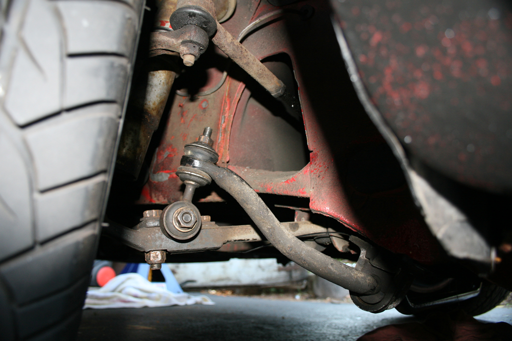
And yes, Hussein, of course I considered that type of end link. Yeah, they are cheap, but I can assure you if you went to the effort of removing the spring and jacking the suspension through it's entire travel ( did you do that Hussein ? ) you would find that link would bind and twist in a most unsatisfactory manner. Not to mention the lost motion of the bar just compressing the rubbers instead of translating motion as it should.....
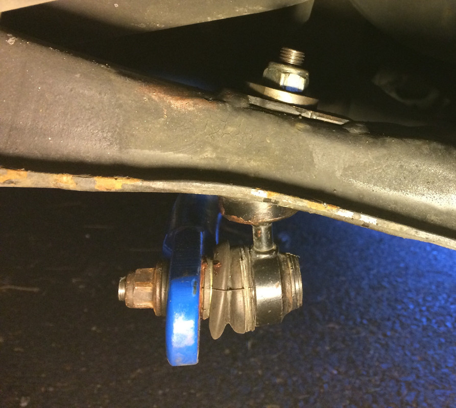
My current chosen end link though should make you happy Hussein. See the pic below. Yup, it is from a Volvo - a C30. Now that is much nicer.
I welcome all thoughts and input.
Cheers, Doug

")