K20 project off to a good start, volume 2

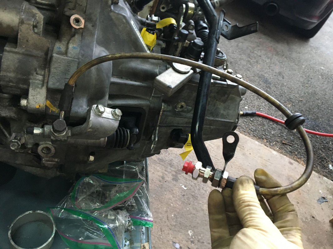
Well, I just got done installing the windshield. First time for me doing something like that and it was probably the scariest thing I have yet done on the car. :eek: Especially after seeing Hussein's post about f...ing up the frame doing his and having to repaint it. That is not an option for me, so I definitely taped it off before I started. I watched some YouTube videos on how to do it, but they were all on newer cars that have the blacked out glass edge that hides the adhesive. I had no idea how long a working time I had with the adhesive, but it turned out to be plenty. I used 3M Single Step Primer first on the pinch weld area and on about half of the rubber U channel trim since the windshield sits on it. I also painted about a 1/4 inch band of the primer on the inside windshield surface and the entire edge. I used 3M 08693 Urethane Adhesive in a regular hand caulking gun. The video guys all had nice power caulking guns, but they were professionals. The adhesive flowed fine although I did let it warm up in the sun first. I made a couple of small rubber standoffs that I pushed into the first layer of adhesive just above the windshield washer nozzles before I set the windshield. They stuck up just a little past the trim so that the windshield would sit on them and keep it at the right height off the bottom edge of the frame. Once I got the glass in place (with a hand from my wife), I went back around and filled in the gap between the glass and the frame with more adhesive and used a plastic tool to smooth it flush with the glass and remove the excess. I had bought two tubes of it, but was able to do the whole thing with just one. Now just let it set for a day and peel off the tape and hope for the best. :)
81 windshield install 01.JPG
 
Nice work! I also used the primer on the glass bonding surface, and the edge. I think I bought fast acting 3M (08609) urethane, as it was setting within an hour, pretty much by the time I had the glass set & was trying to smooth the edge.
 
I got my intake tube back from the welder today. MWB provides two end plates in their K20 swap kit, but you still have to make the tube.
View attachment 13154

I got a couple of mandrel bent 2.5" steel tubes off of eBay, one 45 degrees and one 25 degrees.
View attachment 13155

After a couple of hours with a hack saw, some duct tape, and super glue, I had my intake parts connected.
View attachment 13156

Here it is welded together. My welder friend wasn't too thrilled about the superglue as it created some nasty fumes as it burned off. :oops: Also, I had bought aluminized tubes. That just creates issues with the TIG welding as the aluminum layer tends to bubble. Best to use plain steel. Anyway, here it is ready to go to powder coating.
View attachment 13157

I tried it in to make sure that everything came out as I hoped. I was pretty pleased. :D
View attachment 13158
The air filter is a K&N cone filter for a snowmobile of all things. It has an angle to it that helps to fit the cone in the space better, plus allows a place to mount the air intake temperature sensor.

A couple of notes on the throttle body. The way it comes on the RSX is with two pulleys, one for the throttle and one for the cruise control. I found a couple of cool parts from a company called Karcepts. They make a pulley kit that deletes the cruise control pulley and also provides a nice bracket for the throttle cable. They also make a block off plate to eliminate the Idle Air Control Valve. They claim that the K20 engine runs fine without it. It cleans up the engine a bit and eliminates the need for the hose to run from this IACV to the intake manifold, along side the intake tube. Here is the cleaned up throttle body. I ended up painting it black for the final install.
View attachment 13159

For the throttle cable, I decided to reverse the way the cable would normally go. MWB provides what is basically a long brake cable for a tandem bicycle for the throttle cable. There is a round slug that goes into a hole on the throttle body pulley, then the cable goes through a sheath, through the tube in the tunnel to the gas pedal where the slack is taken up. With my Hurricane AC system installed, access to the connection on the gas pedal is severely restricted, so I put the slug end there and adapted a cable clamp to the pulley. That way, I can adjust it at the engine end. Much easier.

Here's how it looks in the tunnel at the gas pedal. I was able to retain the spring action so the pedal can go to the floor even though the throttle plate is fully open before then. I also shortened the shaft of the gas pedal per MWB recommendations because the Honda throttle body range is less than the Fiat one.
View attachment 13160

Next up is the exhaust.

Rodger, whose (or what) TB did you use? What ID is it? The stock ones are all drive-by-wire, I believe.

Thanks again for all the detail install pics, I didn't know they would be of such specific value to me :D
 
Rodger, whose (or what) TB did you use? What ID is it? The stock ones are all drive-by-wire, I believe.

Thanks again for all the detail install pics, I didn't know they would be of such specific value to me :D
The throttle body is the stock one off of the wrecked 2002 Acura RSX Type S that I bought, that has been cleaned up with some parts from Karcepts and painted black. They were all controlled by a throttle cable, so technically "drive-by-wire", haha. I am assuming that when you say drive-by-wire, you are referring to there being an electrical only connection from the gas pedal to the TB.

The stock ID is 62 mm. A common upgrade is to go to a 70 mm aftermarket one. I had bought a 70 mm one from Hybrid Racing when they were on sale, but to get the performance out of it, I would have needed to enlarge the opening in the intake manifold to 70 mm, as well as the plates from MWB, and build a larger intake tube. If I had thought about it when I had the engine out of the car and the intake manifold off, I might have done it, but it would have been too much work to do that with the engine installed. That would have entailed taking off the AC compressor, serpentine belt, etc. I decided that the stock 210 hp was plenty for me so I ended up selling it to Tim Hoover for one of his builds.
 
Cooling system, Part 2.

index.php

Rodger, would you be able to get a measurement from the water pump/ancillary mount housing flange to the centerline of the return coolant hose where it feeds the Beta T/stat? That would help me in making the adaptor immensely :)
 
Rodger, would you be able to get a measurement from the water pump/ancillary mount housing flange to the centerline of the return coolant hose where it feeds the Beta T/stat? That would help me in making the adaptor immensely :)
This distance?
IMG_2655 measure.JPG
 
Rodger I have been meaning to ask how you did the conversion from the hard clutch line to the k20 slave?
When I was starting to put the car back together, the first things to go in were the clutch and brake hard lines. I took the clutch line to a local guy I found who just makes custom hoses for all kinds of automotive applications. He used to own a brake shop, but now just does hoses out of his garage at home. I had marked where I wanted the clutch line to end under the firewall crossmember. He cut it and put a fitting on and made a bubble flare.
Clutch line mods 01.JPG


He then made a stainless flex hose with the matching fitting on one end and a banjo bolt to fit the slave cylinder at the other end.
Clutch line mods 03.JPG
Clutch line mods 05.JPG

When Darin and Gerald were helping me put the engine in the car, before we hoisted it all the way up, I installed the slave cylinder and we bled the clutch line while we still had good access to the bleed screw. Once bled and satisfied that the clutch was disengaging properly, we hoisted the engine all the way up and secured the subframe bolts. I had the hose guy make the hose long enough so that there was enough length to do that.
Clutch line mods 06.JPG
 
Essentially did the same thing. Are you securing the line to the chassis similar to the stock slave line was? The junction where the hard line and hose connect.
 
Essentially did the same thing. Are you securing the line to the chassis similar to the stock slave line was? The junction where the hard line and hose connect.
No I didn’t. It was not that far from where the line is supported by the grommet through the bulkhead in front of the gas tank.
 
Many thanks, Rodger!

Nice work on the clutch hydraulic setup. I’ve been wondering what approach to take with that. My slave has the flare fitting. I may just figure out a flex line to go from that to the hard line on the body.
For the K20, the clearance to the firewall at that connection is very tight. The banjo bolt allowed the hose to swivel around as we raised the engine into place.
 
For the K20, the clearance to the firewall at that connection is very tight. The banjo bolt allowed the hose to swivel around as we raised the engine into place.

Thanks for the tip Rodger. Was your slave originally supplied with flare fitting, or is it from a different model?

Do you have any overall pics of the engine relative to the firewall, etc? I haven't seen any to gauge the engine/trans placement spatially beyond the couple I found online.
EDIT: I went back & looked at your first couple pages - which have some details. Any additional points to note would always be helpful.

Thank you again for taking the time to help with answering my questions :)
 
Last edited:
Thanks for the tip Rodger. Was your slave originally supplied with flare fitting, or is it from a different model?
It's been a while, but I am pretty sure the stock fitting was a flare fitting. The slave cylinder is the original stock one that came on the car.
 
if getting access to the bleed nipple is tight you could alway's use another hose and extend the bleed nipple to somewhere reachable.
 
For the K20, the clearance to the firewall at that connection is very tight. The banjo bolt allowed the hose to swivel around as we raised the engine into place.

I forgot to ask how long the hose needed to be, as yours sits. I have a 20" line that will fit the slave end (10x1), just need to get a 10x1 to 12.1.25 adaptor for the clutch hard line end.

IMG_6370.jpg
 
The air filter is a K&N cone filter for a snowmobile of all things. It has an angle to it that helps to fit the cone in the space better, plus allows a place to mount the air intake temperature sensor.

A couple of notes on the throttle body. The way it comes on the RSX is with two pulleys, one for the throttle and one for the cruise control. I found a couple of cool parts from a company called Karcepts. They make a pulley kit that deletes the cruise control pulley and also provides a nice bracket for the throttle cable. They also make a block off plate to eliminate the Idle Air Control Valve. They claim that the K20 engine runs fine without it. It cleans up the engine a bit and eliminates the need for the hose to run from this IACV to the intake manifold, along side the intake tube. Here is the cleaned up throttle body. I ended up painting it black for the final install.
View attachment 13159

For the throttle cable, I decided to reverse the way the cable would normally go. MWB provides what is basically a long brake cable for a tandem bicycle for the throttle cable. There is a round slug that goes into a hole on the throttle body pulley, then the cable goes through a sheath, through the tube in the tunnel to the gas pedal where the slack is taken up. With my Hurricane AC system installed, access to the connection on the gas pedal is severely restricted, so I put the slug end there and adapted a cable clamp to the pulley. That way, I can adjust it at the engine end. Much easier.

Here's how it looks in the tunnel at the gas pedal. I was able to retain the spring action so the pedal can go to the floor even though the throttle plate is fully open before then. I also shortened the shaft of the gas pedal per MWB recommendations because the Honda throttle body range is less than the Fiat one.
View attachment 13160

Couple questions here, Rodger if you don't mind :D

Did you find a source for the factory style clip-in cable harness ties, or did you use somethiong else to secure them?

If there is no IAC, does one alter the settings in software to maintain a base idle without it? What happens when load is placed one the systems (AC on, etc.,) that causes the typical voltage drop & idle surge on a EFI car? The only away around that that I can see is to run all new constant & switched power directly from the battery to the engine management, as everything I've done still relies on the factory wiring in terms of system feeds, and I still can get an idle drop when a large current is applied elsewhere (even with the sense feed GM alternator, which maintains 14v). Since I have a working IAC, it doesn't matter.

With the manifold / firewall interference, that area where it is SO close cannot be recessed due to sheet metal proximity to the gas tank, correct? I'm thinking reworking the plenum so the TB flange is offset differently if this is the case.

I'm having trouble seeing how moving the TB that far away from the plenum cannot have some influence on air flow dynamics (or whatever the correct term is)

K20_intake_install_01.jpg


I'm still vacillating on whether to keep AC or not - I love how clean your bay looks here (I've been saving some of your pics for reference, I hope that is OK) - however I see how much work went into making custom lines to keep it so tidy. My engine didn't have a compressor on it, so I'd alos need to buy one, make new lines, etc., so I may end up just removing mine.

K20_engine_bay_final_01.jpg
 
I believe part of doing this is not only to bask in the glorious power but also in having that power provide all the comforts you have become accustomed to. Think of going to any distant place with more than adequate power and cool regardless of how the climate may change.

I wouldn’t step back just yet,

A hose is just a hose...
 
Back
Top