KMead’s Microsquirt Build. Formerly: Looking to use PBS DCNF intake manifold for FI

Yes and no. There are various knock limitations and means to sense or control it, but it isn't something that (as far as I know) can be easily defined or resolved for any one specific engine (I'm referring to modified or tuned engines, not bone stock factory ones). Other than utilizing a reasonable timing curve that is safely within limits. So the question becomes what are those limits (which I think is what you are asking?).

In my opinion the best approach is by performing dyno runs with a highly skilled operator and sophisticated (i.e. extremely expensive) knock sensing equipment to experiment with the reasonable limits. That can get expensive, but considering every engine build is different to one degree or another there really are no shortcuts or "cookie cutter" approaches to it.

I suppose the next best approach might be to just go really conservative with the timing. You'll leave some performance on the table but that's better than destroying your engine.

You can try to do your own testing. With a number of "affordable" means of knock sensing and a lot of road testing, with a passenger running the laptop so the map can be tweaked until you feel comfortable. However this is a highly subjective and risky approach. According to several experts I discussed it with, most such knock sensing devices are not very effective. Although for a street driven engine that isn't overly strung it may suffice (assuming the person has some idea of what they're doing)?
The talk of timing curves causing head gasket failures genuinely concerns me (and probably should concern kmead and others, too). Is there somehow a knock limitation? Or is there some physical weakness that causes failure if the timing is pushed towards (or slightly beyond, accidentally) mean best torque?

The distributor-based map works well as a baseline, but most of the gain is being able to adjust beyond the bounds of a mechanical system...and stock is absolutely not peak power and efficiency throughout the load and rev range.

Are the head gaskets that terrible?
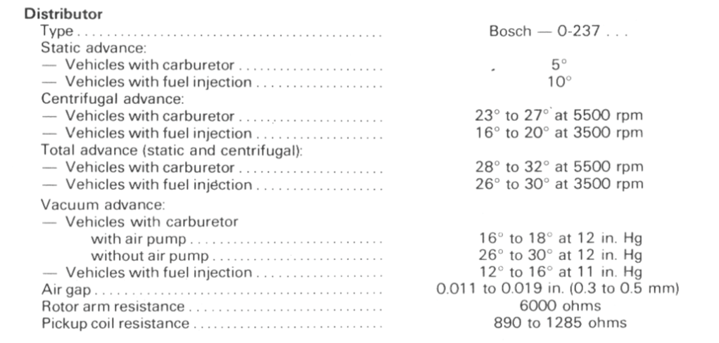
I will be starting with the way Hussien had the timing map. I hadn’t parsed the mid range timing as the problem he had been having but given most of the actual use of a street engine is in that mid range it makes sense that extreme pressures caused by preignition could occur there.

As for the runners, Hussien had straightened them and opened them up based on feedback from SteveC, as I recall, along with going to a straight fuel rail which gave the opportunity to use modern injectors and got rid the flex lines which was always an unfortunate kludge related to the time the injection system was glommed onto a basically carbureted engine.

The Bosch COP assemblies are of real interest, definitely go with the ones with an integral igniter. I may try to get creative with the bracket to work around the issue of the dip stick. Thanks for that pic Björn Nilson, some real food for thought there.

I would say, speaking from a wealth of ignorance, that most of the gain with this engine is higher compression, larger valves and a better cam which is then enhanced by a more precise injection system which can also control spark events. Yes, pushing the hairy edge of ignition event timing is the other key but absent a known system for this engine to deal with knock sensing it will be hard to chase that edge without going through multiple head gaskets which are specifically intended to be the weak point to avoid other massive mechanical destruction. The intake manifold may still be a limiting factor as may be the exhaust.

We shall see. Months to go before anything substantial is likely to occur.
 
Last edited:
I have this Bosch P65 Motorsport coil on my UT engine, controlled by ECU. A (small) separate ignition module is needed as well. These coils are flexing which makes them fit on our engines.
View attachment 71079
I have them mounted on a bracket
View attachment 71080
Perhaps moving the one off to the side, breaking the nice rhythm, would give you more room to access the dipstick. Keeping the flange along the top continuous would give you back some structure where sparing out the material is lost.

A0AD3734-8AF3-48C9-99DF-F68452A5052B.png
 
Another coil option might be the "coil near plug" type. They are almost the same as those Bosch units but they have a short 'ignition wire' lead that is more flexible and allows more latitude with mounting.

These are the common GM "LS" ones, but there's lots of others - including with or without drivers/ignitors:
CoilNearPlug.jpg
 
The talk of timing curves causing head gasket failures genuinely concerns me (and probably should concern kmead and others, too). Is there somehow a knock limitation? Or is there some physical weakness that causes failure if the timing is pushed towards (or slightly beyond, accidentally) mean best torque?

The distributor-based map works well as a baseline, but most of the gain is being able to adjust beyond the bounds of a mechanical system...and stock is absolutely not peak power and efficiency throughout the load and rev range.

Are the head gaskets that terrible?

We're talking about Volvo timing maps here - The Fiat only runs about 30º max- the Volvo maps take it way over 40º - I kept putting off figuring out how the edit the Volvo bins. As said, running the stock advances curve used with the mechanical advance dist. is the safest way to start. The MS ignition parameters will likely be easier to figure out that messing with overwriting a OEM system meant for a different engine.

Example:
X19-LH24-00095.png


I used the Bosch chart to plot the timing

X19-LH24-00120.png
 
Last edited:
Perhaps moving the one off to the side, breaking the nice rhythm, would give you more room to access the dipstick. Keeping the flange along the top continuous would give you back some structure where sparing out the material is lost.

View attachment 71084
Accessing the dipstick is not the problem. The problem is putting it back as you have to bend over, more or less laying on the engine to be able to see the dipstick hole. This is a little bit tricky even on a stock engine without the bracket. But as usual, with some training you learn to feel to target the hole😋.
Maybe drilling holes in the bracket would make the dipstick hole visible without loosing structure.
 
Another coil option might be the "coil near plug" type. They are almost the same as those Bosch units but they have a short 'ignition wire' lead that is more flexible and allows more latitude with mounting.

These are the common GM "LS" ones, but there's lots of others - including with or without drivers/ignitors:
View attachment 71085
Quite a few variations between LS1. 2 and truck coils as well as multiple mounting approaches.
 
Last edited:
Another coil option might be the "coil near plug" type. They are almost the same as those Bosch units but they have a short 'ignition wire' lead that is more flexible and allows more latitude with mounting.

These are the common GM "LS" ones, but there's lots of others - including with or without drivers/ignitors:
View attachment 71085
I used AEM smart coils in the "stock" ignition component position with the thought that it mat keep them cooler.

The ignition wires sre longer though.

DSC_0471.jpeg
 
The MicroSquirt includes two coil circuits, but no ignitors/drivers. With its "semi-sequential" mode you can use one of the coil circuits to fire two of the siamesed cylinders together, and the second circuit to fire the other two siamesed cylinders together. That means you really only need two coils, each being a "dual" coil configured to fire two cylinders. This design (with two "dual" coils) is utilized by several OEM ignition systems and many of them are "smart" coils.

I went with a VW unit of that type, designed for their turbo engines (among others). It houses the two coils in one module with one wire harness connector. I chose it because it includes the ignitor/driver circuitry internally, it's very easy to wire, mount, configure (with MicroSquirt), and mostly because I happened to have two new ones on hand already. By mounting it on the firewall directly across from the middle of the head it will stay cooler than coils mounted onto the head, and the four plug wires are still very short (about as short as coil-near-plug coils).

Here's the VW coil:
LightFlywheel.jpg


I failed to take pics of it mounted during the mock-up, but I'll use this pic of someone else's engine bay to illustrate the location/layout of the coil:
IMG_3396 - Copy.jpg
 
We're talking about Volvo timing maps here - The Fiat only runs about 30º max- the Volvo maps take it way over 40º - I kept putting off figuring out how the edit the Volvo bins. As said, running the stock advances curve used with the mechanical advance dist. is the safest way to start. The MS ignition parameters will likely be easier to figure out that messing with overwriting a OEM system meant for a different engine.

Example:
X19-LH24-00095.png


I used the Bosch chart to plot the timing


X19-LH24-00120.png

Basing the trends on each axis off of the distributor is a good start, at least until some dyno time can find optimal timing throughout the rev range (based on cylinder pressure and turbulence effects). Certainly that's far better than using the volvo timing map for a totally different engine.

I'd be curious to see just how much one can gain from a properly optimized map at some point though, I'm sure there are gains to be had.
 
Back
Top