Rupunzell
Bernice Loui
These are press into the FR-4 (fiber glass) PC board connectors, famous for becoming intermittent over time, aging, temperature cycling, mechanical stress and ... Many years ago when ATE introduced their ABS system that was used in deluxe motos at significant expense and put ABS into the very desirable moto option list, ATE decided to produce a cost reduction_ed version of ABS. It was used in VW and some others. This ABS system by ATE became intermittent over time causing all sorts of ABS system nightmares for owners.
-The problem was due to press into the PC board connectors like this.
This design and why they are used is strictly driven by cost and profitability. IMO, they should NEVER be used in a mechanically stressed environment like a moto as they are going to fail, not if, but when they will fail. The connection relies on mechanical resilience of the FR-4 PC board material and connector pin. Problem with this design belief, fiber glass will relax over time due to temperature cycling, vibration, corrosion from moisture and more. Adding to this problem, the plating on these boards can corrode and oxidize.
-Solution to this problem is to simply solder ALL The connectors to the PCB and mechanically stabilize them as how it was done here.
~~~~~~~~~~~~~~
The other variation of this problem, insulation displacement connectors. They are another cost reduction profit driven electrical item that should not be use in mechanical system like motos as they are subject to similar modes of failure as these press in PC board connectors.
Bernice
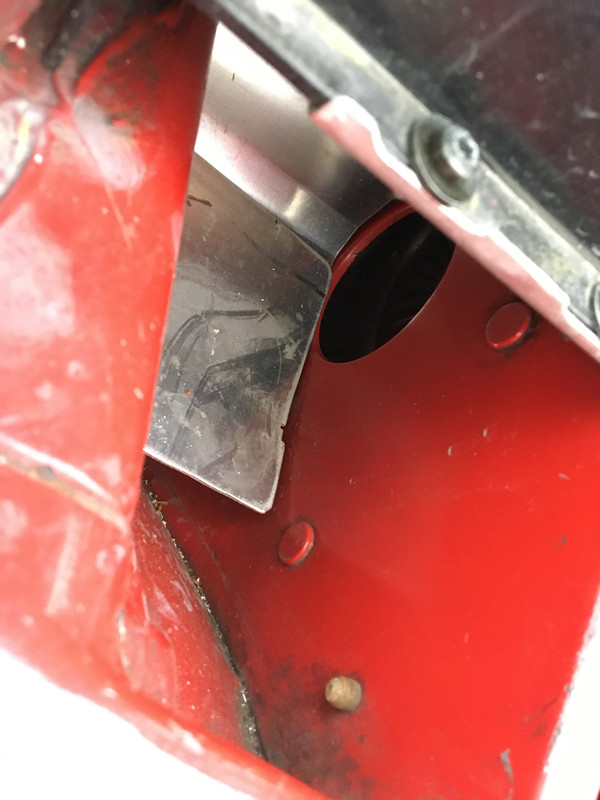
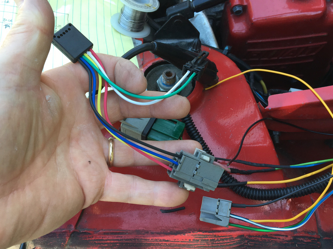
Aha! Looking behind, I could see the large red spade was loose - unfortunately not the female spade at issue- the male connector had separated from the circuit boardafter numbering and removing all the harness plugs, I came to this:
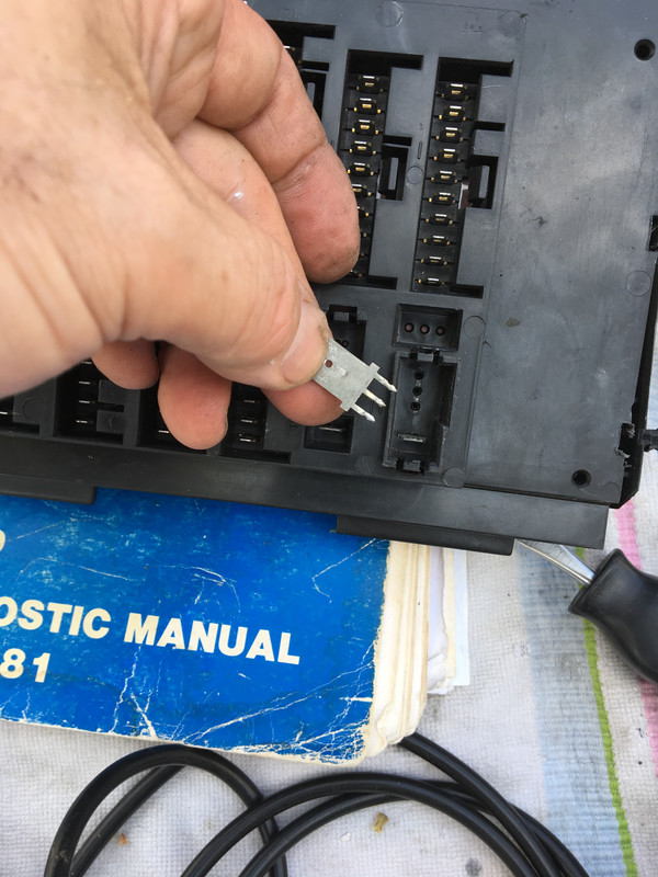
Not about to buy a new or used box - I want to drive it tomorrow- so I took it apart:
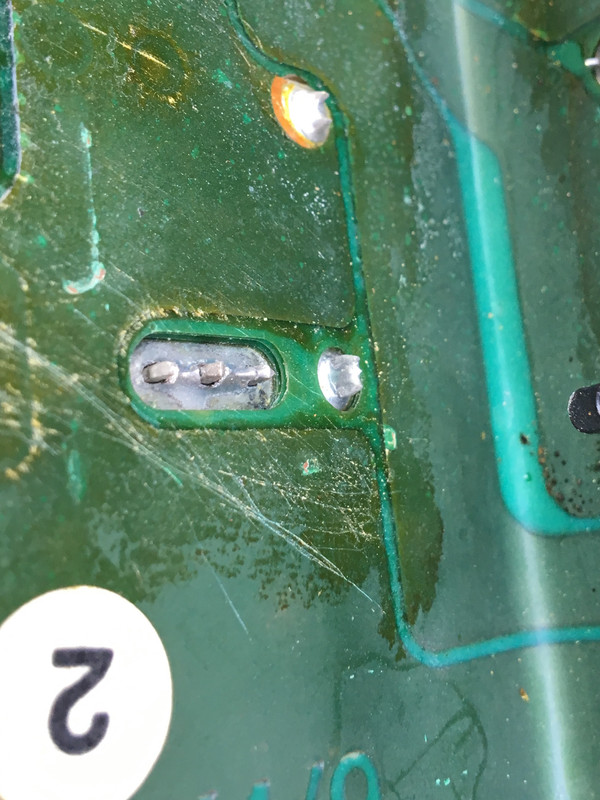
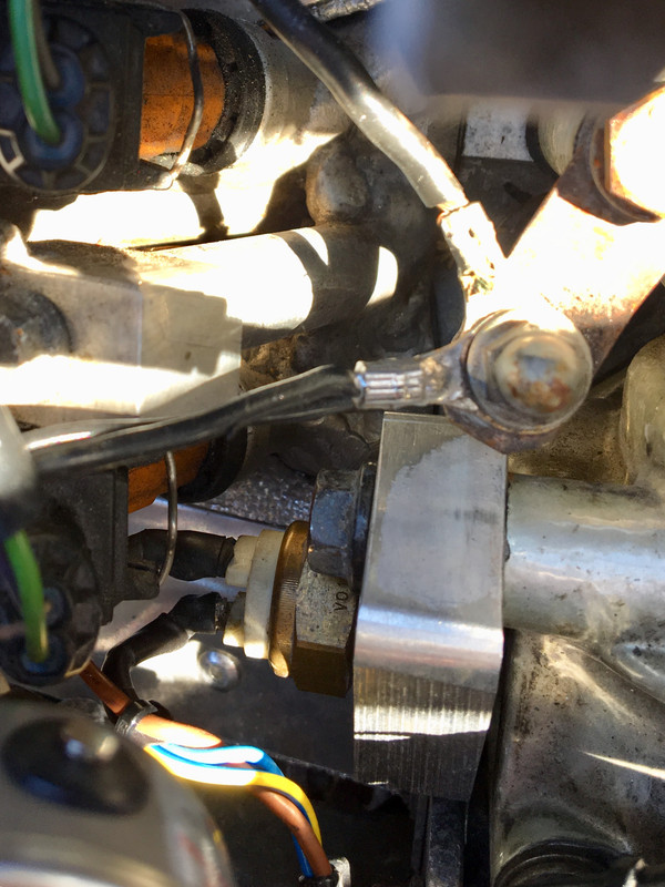
Resoldered the joint, and then epoxied the socket side base and the circuit side, to help take some of the load off the connector when the box is moved around. Only up to the connector shoulder seen in the first pic.
That fixed all the problems except the interior lights and radio. After a range of circuit testing I realized the fuse wasn’t the “Services” fuse, but the one described as “lighter”. Blast. Turned out the element was shorting in a fairly random fashion - I had noticed the radio & lights out from time to time, but the fuse had never blown immediately before today.