Lower Engine Mount Sources

There are two versions of the lower mount?
If you look at the mounts with the arrows. The holes in the first picture are higher and more upright than the holes in the second picture. The rubber width between the holes is smaller in the second picture and therefor weaker. Less rubber below the rod that tranfers all the engine weight to the crossmember.
 
The holes in the first picture are higher and more upright than the holes in the second picture.
Oh, by "holes" I think you mean the voids cast into the rubber (air gaps). When you said "the holes" I thought you meant the bolt mounting holes for the brackets. That would be an entirely different mount. Sorry my misunderstanding.
Those air-gap voids in the rubber might be a factor of who makes them rather than what year they are made for? Because I don't recall ever seeing listings for early or late versions of the mount (aside from the exhaust arm Huss mentioned).
 
It would be nice to redesign the mount so all the load isn't all bearing down from that central pin.
Today I removed the cross-member and lower mount to look at possible replacement ideas. One feature of the factory's 'central pin' design is it can allow some pivoting of the entire engine/trans assembly relative to the rigid cross-member. This can be seen when the 'dog-bone' mount is removed, the engine can be rocked fore-aft as everything pivots below. If a redesigned lower mount was made that removed the single central pin (as suggested above, to distribute the load more), the angle of the engine/trans assembly would be fixed. I suppose as long as that angle was correct to align with the other two engine mounts, then it might not matter there is no pivoting?

After looking at the available space, location of the mounting bolts on the trans end, and the shape of the cross-member, I don't think one of the generic American type transmission mounts (like I showed in earlier pics) can be used. In fact I don't think any of the above mentioned optional mounts can be used. Any mount that allows the engine/trans to rest on top and the cross-member to ride below is simply too tall. In addition to space limitations, they would reduce ground clearance. Therefore the factory design of allowing the engine/trans to 'hang' below the cross-member will likely have to be retained. This makes it unlikely to use anything other than a 'central pin' design (but not impossible).

Regarding finding optional 'factory style' (central pin)mounts. The related thread discussing casting urethane mounts is one solution. However using urethane (even the lowest duro stuff) is very rigid for a street vehicle. Perhaps finding a single central pin mount from another vehicle and fitting it into the Fiat brackets? Particularly one for a heavier vehicle. Something like this might work if the cross-member and retaining bracket was modified 'round' (I believe this pic shows it upside-down):
199.120.jpg

In addition to the overall outside diameter, the diameter of the central bushing (for the pin) and the width will need to work.
 
Did my lower mount today. I concur that there is just no way to add another style mount without reducing the ground clearance.

This is CV/crossmember clearance with new mount

BA182926-_C49_A-4_A6_E-8123-_BA1_F8782_CE1_C.jpg


230562_DC-19_DC-43_CF-9_AFA-_F44_B9_B0_DB801.jpg


911_A0702-34_F3-4_DFF-8_DFE-1239_D6_D35794.jpg
 
Even if the round type of mount was used (from another vehicle), getting it to fit the bracket is only half of the battle. The center pin must be at the correct location relative to the cross member in order to maintain the proper clearance of the CV joint. Really not a likely outcome.

Molding or casting a replacement stock style mount seems to be the best plan. However something more compliant than urethane would be preferred.
 
Maybe instead of reworking this mount, adding a third mount off the frame rail at the transmission to offset the current weight load? All the FWD Volvos I work with have had that setup - the center(ish) mount on any of those is typically lighter duty (on some it's the torque mount), with heavier mounts at the extremities. Haven't looked at all at whether there is anything to attach to yet.
 
Definite possibility. I seem to recall there are a couple unused holes on the bell housing. For that matter maybe two small additions, one on either side of the existing lower mount.

One question I've been wondering is if there is a need to retain the "pivoting" function of the center pin/lower mount. In the stock form it allows the entire engine/trans assembly to move fore-aft about its axis. The torque strut (dog-bone) then controls that motion. I assume the purpose is to allow some compliance for the torque reaction movement with acceleration-deceleration. I think that is why the dog-bone has such soft bushings. This 'compliance' would help smooth out actions like taking-off from a stand-still, gear changes, etc. It also allows some drivetrain vibration to be absorbed without being transmitted into the bodywork. On a performance (track) application such movement is not desired, but on a street driven car it creates a much smoother ride quality.
Adding a second lower mount will prevent the fore-aft pivoting movement. But I guess the question is if that would be a bad thing or not.

Another possibility I've considered is the addition of a lower mount "insert". These are common for other vehicles. It is typically a urethane piece molded to fit into the air-gaps (open voids) that are cast into the stock rubber portion of the original style mount {example shown below}. By filling-in those open areas on the rubber bushing it makes it firmer, less able to collapse, and limits the overall movement some. Yet the rubber still retains its natural compression nature to absorb vibration. This would be fairly easy and inexpensive to make. They have mixed results with them in other applications; depending on the original mount's design, location and quality for the particular vehicle. One factor might be the variation between replacement Fiat mounts for the location and shape of those air-gaps. Its been noted already by "Mxgrds" there are at least two versions of how the rubber is cast.

Watch this installation demonstration:

srt_prothanes.gif


Some are one-piece that insert from one side only:
20150503_205307.jpg


While others are two-piece that insert from both sides:
download (1).jpg


I saw one example of a "DIY" version:
diy-feature-1.jpg


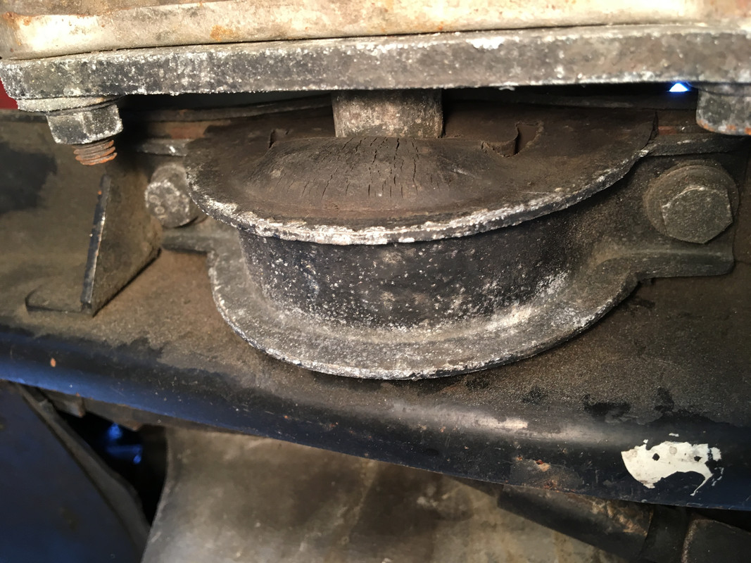
For the X's lower mount it would fill these holes:
x19.jpg


This may not be as effective on the X as with other mount designs, where there are more voids and they are located more below the mass center. The rubber portion at the bottom of the X's mount can still break down and deform. But maybe not as much?
On one of my used mounts we can see where an insert may have offered some benefit. Both voids are clearly very collapsed, especially toward the lower aspects (red arrows). The solid rubber portion at the bottom is also compressed (yellow arrow). Would maintaining the shape of the voids reduce the rubber's collapsing at the bottom?:

004.JPG


Compare this with the 'new' mount above to see the changes and decide if you think an insert will be of much benefit.
 
  • Like
Reactions: RMW
This might be a little out there, but another idea has come to mind (I know, my mind is rather out there anyway).

In an effort to prevent the 'collapsing' or 'smushing down' of the rubber bushing toward the bottom of the mount (yellow arrow in last pic of prior post). While one side of the bushing has the flat metal mounting plate (transmission end of the mount; can be seen in the back of the referenced pic) supporting it, the other side of the rubber casting is open. If the rubber could be 'sandwiched' between two flat plates (one on either side), it might be prevented from deforming outward and collapsing down.

To add a second plate up against the open side of the rubber bushing (similar to the trans bracket on the other side), the center pin could be drilled and tapped to accept a retaining bolt. Then a plate the shape of the rubber can be bolted up against that side. Now the rubber is supported on both sides. It might be possible to design this in a way to actually compress the sides of the rubber and increase its firmness. There would need to be room left around the edges of the added plate to allow for movement of the mount, without metal to metal contact by the plate.

Really not sure how much this would help, but it derived from the last post about adding inserts into the rubber voids. I'd prefer to use the method with two urethane inserts, one half on either side. But something needs to hold each one into place. The existing plate on the transmission end of the mount will retain the half on that side. Something else will need to do this on the 'open' side of the bushing. If you look back at the sample pictures in my last post, you will see a large washer (of either metal or urethane) is often used to do this. So why not make it a heavier plate shaped to conform to the contour of the rubber.
Also the urethane insert on the 'closed' side (where the trans bracket plate exists) could have a larger 'flange' or lip cast as part of it to help achieve this 'sandwiching' effect from the back side. This will help add to the compressing effect mentioned above, by taking up the space between the rubber and the rear mounting plate.

I'm sure this needs further development. Just thoughts so far.
 
Definite possibility. I seem to recall there are a couple unused holes on the bell housing. For that matter maybe two small additions, one on either side of the existing lower mount.
Compare this with the 'new' mount above to see the changes and decide if you think an insert will be of much benefit.

Don't think inserts will help. Mine have all failed the same way, compressed out the bottom. I was even considering welding small plates across the lower 3rd to keep the rubber from expanding outward...

X19_Trans_Mount.jpg
 
Today I tried to separate the center pin/trans half of the mount from the center sleeve/rubber half. But the pin is frozen and I was not able to separate them. I was hoping to accomplish this without tearing up the rubber in order to play with some design ideas. But it does not look like that will be possible.
 
Today I tried to separate the center pin/trans half of the mount from the center sleeve/rubber half. But the pin is frozen and I was not able to separate them. I was hoping to accomplish this without tearing up the rubber in order to play with some design ideas. But it does not look like that will be possible.

Pretty sure the issue is that they are a press fit, not so much that it has frozen. Otherwise the mount wouldn't 'torque' under load, it would simply rotate around the pin.
 
Sorry, again didn’t read all carefully, but to get out frozen bolts in bushes helps a good drillhamer, use it only in on hammer option, not drilling.
 
Pretty sure the issue is that they are a press fit, not so much that it has frozen. Otherwise the mount wouldn't 'torque' under load, it would simply rotate around the pin.
Could be, however the only other time I've had one off it separated fairly easily. This one is rusty (like everything on this car), so figured it is just frozen. I had the impression the concept was for it to rotate around the pin; allowing movement of the power-train which is controlled by the "torque strut" (hence the name). That would certainly help to extend the life of the lower mount's rubber portion. Anyway, I tried using the hydraulic press to separate it until the fixture broke, and still no movement of the pin. So this one is beyond a press fit.
 
Doug/RX1900 comissioned a build of these and offered them for sale here. Perhaps he has a few left?
About two years ago Doug offer a kit, lower mount + bracket adapter for the 1500. I'm a satisfied customer. There is pictures of his kit and after two years the gap between the support and axle joint.
oqdRkkI.jpg

cseMFck.jpg

UJP6BMc.jpg

XnSrjjf.jpg


Yves
 
Thanks Yves. As I recall the focus of his product was the add-on extension arm for the exhaust mount. This made it possible to use the standard lower engine mount on the cars with the exhaust that had that arm. I believe the actual engine mount (which was an option from him, the arm was the primary item) was just a standard vendor mount? Yours seems to be doing well. How many miles on it? I see the lower portion of the rubber is beginning to show early signs of compression, which is common to all stock mounts. Certainly no criticism of Doug's mount nor your experience with it. Just trying to learn if it is anything different than the usual items on the market? Hoping it is, so that we can get a better product somewhere. Appreciate some added info on it, thanks.
 
Yves' post above brings up a good point.
On those models that have the exhaust support bracket hanging off the lower engine mount. The added weight and resultant torque of the arm (with exhaust system attached) will place added rotation (twisting) on the lower mount. On my '85, when I unbolted the dog-bone torque strut the engine flopped over to the side. And the rubbers in the dog-bone were compressed on one side of each bushing (corresponding to the direction of the engine's rotation on release of the dog-bone), despite only being on the car for less than 200 miles. Also the lower mount's rubber was twisted with uneven wear to that direction.
Additionally I wonder if any of the exhaust heat transfers up the arm to the lower mount, thereby heating the rubber and fatiguing it?
It seems the exhaust support extension arm might be adding to the short life of both the dog-bone and the lower mount. Could eliminating that arm help on those models? I think some of you are running without it, and still experience the same short-lived mounts problem, so not likely a major issue.
 
Thanks Yves. As I recall the focus of his product was the add-on extension arm for the exhaust mount. This made it possible to use the standard lower engine mount on the cars with the exhaust that had that arm. I believe the actual engine mount (which was an option from him, the arm was the primary item) was just a standard vendor mount? Yours seems to be doing well. How many miles on it? I see the lower portion of the rubber is beginning to show early signs of compression, which is common to all stock mounts. Certainly no criticism of Doug's mount nor your experience with it. Just trying to learn if it is anything different than the usual items on the market? Hoping it is, so that we can get a better product somewhere. Appreciate some added info on it, thanks.

No he had the mounts specially made to his spec.

He had a run made, sold some here and then sold the rest to Eurosport who attempted to have more made by the same vendor. Unfortunately the vendor chose not to make any more so the only ones out there are the lighter duty ones intended for a 4 speed with a 1300, which are not reccomended for a 1500.

I think I got his last one last summer.
 
Back
Top