
Matthew
True Classic
Since this post has been stickied here is the link to the post that covers the hardware and also a link original thread this came from.
http://xwebforums.org/showpost.php?p=99879&postcount=16
http://xwebforums.com/forum/index.php?threads/12955/
When I first began researching this project I started by reading a lot. Here is a list of Megasquirt and tuning resources that I used:
Megamanual
MS Extra Manual
MSExtra Forums
Megasquirt Forums
A write up about installing Megasquirt on an X1/9 specifically.
DIY AutoTune Tech Articles
EFI University
I read the Megamanual a number of times and planned out how I was going to do the install. After a couple of months I realized that I had MS2 Extra firmware which has a whole other manual :doh:
Once I started collecting the parts I spent a lot of time tracking down all the supplies I was going to need to build the harness and do the install in a way that I would be happy with. Here are some of the places I used for the supplies and parts I needed:
DIYAutoTune Pretty much all the major MS components and wiring.
Waytek Wire, connectors, terminals, relays, crimpers etc.
Ballanger Motorsports Connectors and terminals
Eastern Beaver OEM type terminals, connectors and crimpers.
Digikey Electrical components of all types.
Vetco Electronics Miscellaneous electrical supplies (Local to me)
Fry’s Electronics Miscellaneous electrical supplies (Local to me)
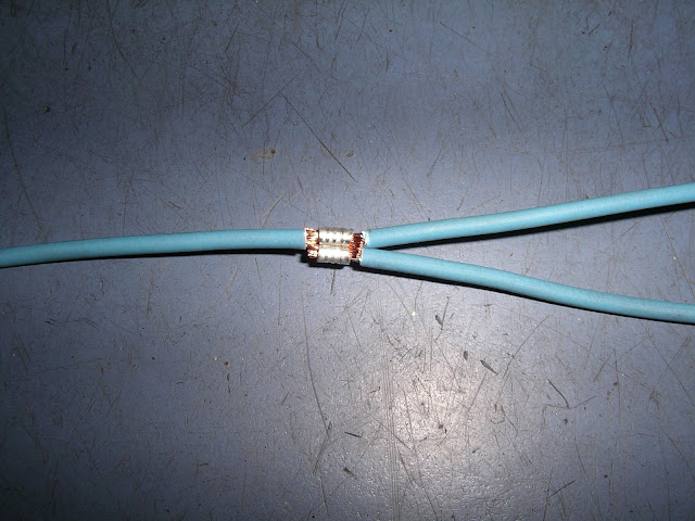
I wanted to build a harness that was as close to OEM quality as I could reasonably get. It would have been easier to just use regular and water proof butt connectors and electrical tape and it would have worked fine. However, that wasn’t the look I was after. With the exception of the EDIS harness all the connectors were crimped directly on the harness rather than spliced on pigtails. Were I needed to splice I used small open barrel connectors and adhesive lined (dual wall) heat shrink.
There were three sizes that I used. From left to right Digikey part numbers A29929CT-ND, A100600CT-ND and A100590CT-ND

They are a little tedious to work with but they make really nice compact splices that won’t leave a big lump in your harness. For tinned wire or sensors where excellent continuity was critical I also soldered the splice.
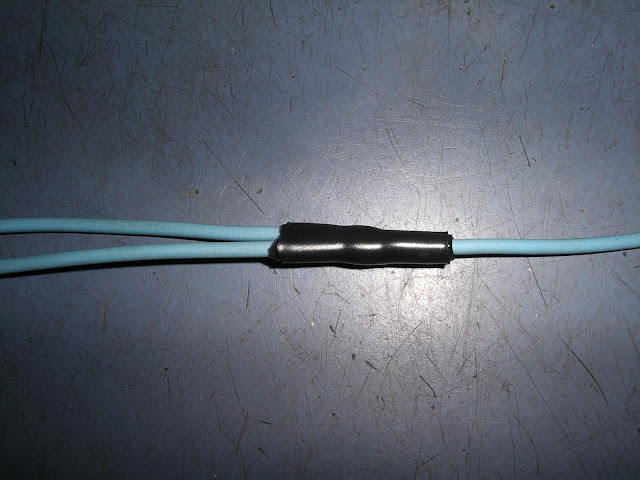
Here is a finished splice with adhesive lined shrink tube over it.
When working with connector terminals the tools required can be expensive. I have a bunch of crimpers but only use three or four of them most of the time. Unfortunately there are dozens of open barrel crimpers and it was rather hard to figure out which ones I needed. The crimper that worked best for the splices turned out to be a $20 one I bought at Vetco.
For the wire harness I started with a DIY AutoTune 12’ Megasquirt harness. The wires are high quality TXL automotive crosslink wire labeled ever 4”. This made building the harness almost fool proof.
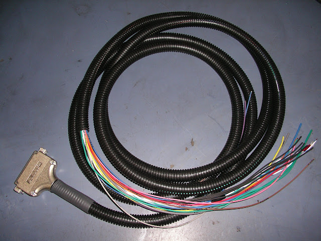
To shield the wires to the crank position sensor and the two wires from the MS to the EDIS module I used ¼’ tinned copper tubular braid. I put the wires need to be shielded through the braid and soldered a wire at one end that went to ground. One of the wires for the EDIS from MS on the DIY AutoTune harness is already shielded but since the other one wasn’t I just put both through. It doesn’t hurt to have too much shielding. I finished the shielded wires by covering the whole thing with shrink tubing. The finished product was too big to fit in the split loom so I wrapped it on the outside. This worked okay because the EDIS wiring leaves the main harness to go over to the right side of the engine bay immediately after it exits the spare tire well.
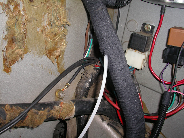
Here you can see the harness inside the car with the shielded wiring running on outside of the split loom. Also you can see how I ran the vacuum tube for the MAP sensor inside the harness using Cohline 3010 vacuum tube.
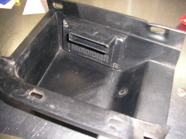
The EDIS module lives under the right plastic cap next to the engine lid. I attached it with double back tape. Once it’s installed on the car you can’t even tell it’s there.
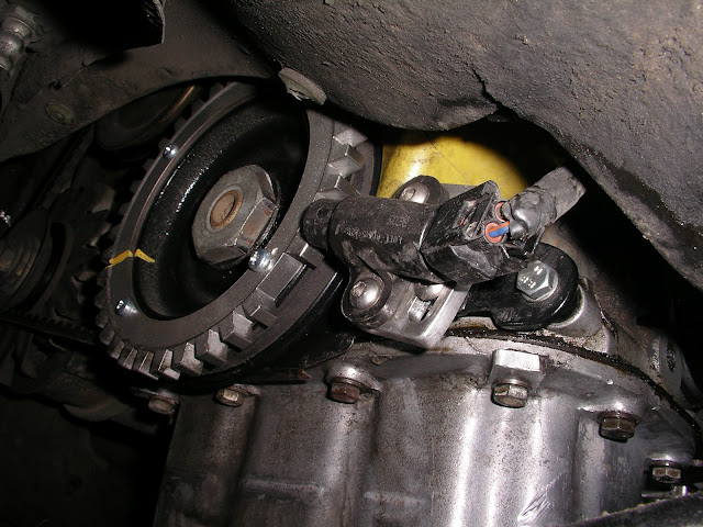
The crank sensor is on a custom mount bolted to the front seal plate. The trigger wheel is a stock ’91 Ford Escort part that has been bolted to the front of a slightly modified stock Fiat crank pulley. This was fairly simple to make but required some machining and welding. I would have rather had the trigger wheel behind the pulley but there was too much fabrication involved and the only source I had for one like that was unable to make it for me.
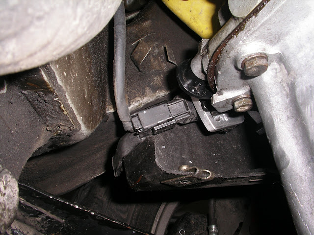
The sensor is a little close to the plastic splash shield but it works.
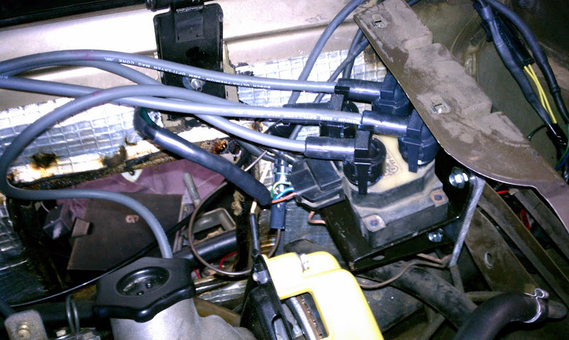
The Coil I mounted using a coil mount from a ’91 Ford Escort and a piece of ¼” aluminum. I really want to mount the coil in the same place the distributor cap was. I will eventually try again to get the mount I need to do that and move the coil but for now this works fine.
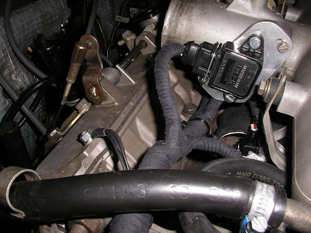
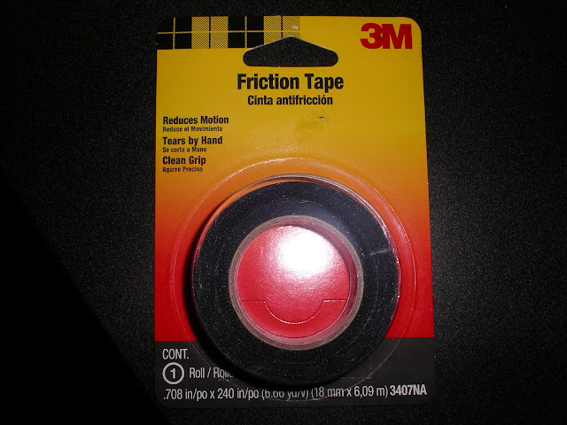
The rest of the harness in the engine compartment was pretty straightforward. I just routed the wires to the sensors and injectors, crimped on the terminals, inserted them in the connectors, put split loom over the wires and wrapped it up with 3M friction tape from Home Depot.
I attached the wire harness to the factory locations under the throttle body using fir tree mounts from Waytek. The vacuum pipe exits the harness near the #1 injector and attaches to manifold vacuum with a “t” fitting in the fuel regulator vacuum hose.
All but one ground wire for MS attaches to a single ring terminal at the factory location on the valve cover. The remaining ground wire is sliced to several more wire inside the harness and provide a ground return for each of the sensors.
Fir tree mount

I also made a dummy harness for the cold start injector. I didn’t like that it looked like something was missing. I have plans to build a blanking plate/fuel pressure test port combo to replace the cold start injector eventually.

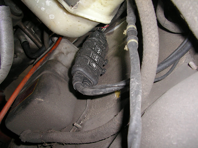
The wide band controller is an Innovate LC-1 and is mounted to a bracket I made and attached to the carbon canister bracket. This puts it in the perfect location to connect it to the oxygen sensor. The wiring for the controller I routed along the factory harness behind the coolant bottle and air filter then along the firewall and into the spare tire well.

The LC-1 requires occasional calibration. For that purpose it comes with a button and LED that connects to a wire from the controller. The button is wired to ground the wire when pressed. They don’t provide any neat way to set this up so I installed the LED and switch in a small project box that I bought at Fry’s Electronics.
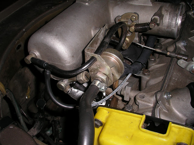
Wiring the power supply for MS, the injectors, fuel pump, WB controller and idle valve required removing the Bosch double relay. The double relay is used for several reasons three of which are no longer needed with Megasquirt and one that will not work. The double relay turns on the fuel pump circuit when the ignition is turned on but only if the switch in the airflow meter is closed. Since MS grounds a relay to turn on the fuel pump is can’t be used with the double relay without adding yet another relay to control the double relay. That would be too messy in my opinion. The double relay also serves as a link between the body harness and FI harness to allow the starter circuit to control the cold start injector. That feature is no longer needed. It’s my belief that the main reason they used the double relay instead of two less expensive relays is because it was the only way to keep the FI and body harness completely separate which simplifies installation on the assembly line. Anyway, do yourself a favor and ditch the double relay.
The double relay has three power supplies. One is a large red wire that comes directly from the battery and is an unprotected circuit. This kind of bothers me but it’s worked for 30 years so I kept it as is. There is also the fuel pump circuit that comes from the fuse box and is hot all the time. Last but not least there is the power from the fuse box for the double relay. This one is hot only with the ignition on.
These three power supplies are all you need to make MS work. Two relays take the place of the double relay. One is for the fuel pump and the other is the “main” relay which will power MS, the injectors, the idle valve and the WB controller. The switched power wire goes to terminal 86 on the main relay and the large red wire goes to terminal 30. Since the large red wire is an unprotected circuit the wire from terminal 87/87a on the main relay needs to go directly to a fuse box that will distribute power to all the devices. Terminal 85 on the main relay goes to ground.
The B+ wire from the fuel pump fuse goes to terminals 86 and 30 on the fuel pump relay. It supplies power to the relay winding and the fuel pump once MS grounds the relay turning it on. The wire to the double relay that goes to the fuel pump can be connected directly to terminal 87 on the fuel pump relay. Since the circuit going to terminal 30 comes from the fuel pump fuse no additional protection is need. Terminal 85 connects to pin 37 of the MS harness.
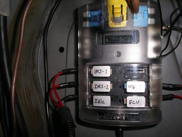
I ran the power from terminal 87 of the main relay to a Blue Sea Systems 5025 6 position fuse panel with a ground bus. The Blue Sea Systems fuse panels are the nicest I could find and are much better than anything the auto parts stores sell. These can be found at marine supply store. I got mine from West Marine.
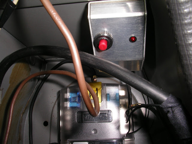
Here is the relay setup. I used interlocking panel mounted relay sockets from Waytek. These accept the factory relay terminals which Waytek also sells.


Here is the fuse box. It supplies power to the injectors, idle valve, Megasquirt and the WB controller.
Once everything is installed the software needs to be setup. This really should not be attempted without many hours studying the Megamanual and MS Extra manual. However, I will share some of the settings that are known to work with the X1/9 fuel system and what I am currently running. Much of this information I found here on Xweb or various places around the internet.
Required fuel is the setting that tells MS how big your injectors are and how big your engine is so it has some idea how much fuel they inject and how much they need to inject. 15 is the number most people suggested and it seems to work well

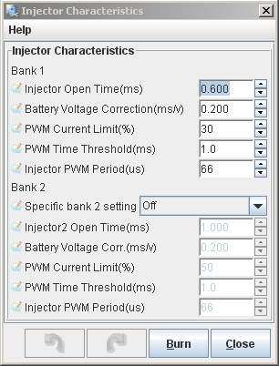
The Injector Characteristics setting tells MS what kind of injectors you have. The X1/9 injectors are low impedance “peak and hold” injectors. This means they need a certain current to open them and a lower current to keep them open. If you run in high impedance mode it will blow the injector fuses. These settings work well for me.
The GM IAT sensor is plug and play with MS but the Bosch coolant sensor requires some calibration. Under Calibrate Thermistor Tables select “Coolant Temperature Sensor” from the upper drop down box and “Saab (Bosch)” from the lower box. Once you write to controller the CTS will read properly.

When I first started working with the MS setup I was using the original tuning software called Megatune. I got really frustrated with it and finally gave up. I felt like you need to be a software engineer to understand the setup procedure. I switched to Tunerstudio MS and found it to be much easier to use. Both are free but the registered version of Tunerstudio ($40 I think) has features that you will want.
I still need to install the idle valve and setup closed loop idle and I will let everyone know how that works out. I probably won't make it back to the dyno for a few months so don't expect any exciting numbers soon.
I tried to be as detailed as reasonably possible but if there is anything I left out remind me and I’ll add it.
http://xwebforums.org/showpost.php?p=99879&postcount=16
http://xwebforums.com/forum/index.php?threads/12955/
When I first began researching this project I started by reading a lot. Here is a list of Megasquirt and tuning resources that I used:
Megamanual
MS Extra Manual
MSExtra Forums
Megasquirt Forums
A write up about installing Megasquirt on an X1/9 specifically.
DIY AutoTune Tech Articles
EFI University
I read the Megamanual a number of times and planned out how I was going to do the install. After a couple of months I realized that I had MS2 Extra firmware which has a whole other manual :doh:
Once I started collecting the parts I spent a lot of time tracking down all the supplies I was going to need to build the harness and do the install in a way that I would be happy with. Here are some of the places I used for the supplies and parts I needed:
DIYAutoTune Pretty much all the major MS components and wiring.
Waytek Wire, connectors, terminals, relays, crimpers etc.
Ballanger Motorsports Connectors and terminals
Eastern Beaver OEM type terminals, connectors and crimpers.
Digikey Electrical components of all types.
Vetco Electronics Miscellaneous electrical supplies (Local to me)
Fry’s Electronics Miscellaneous electrical supplies (Local to me)
I wanted to build a harness that was as close to OEM quality as I could reasonably get. It would have been easier to just use regular and water proof butt connectors and electrical tape and it would have worked fine. However, that wasn’t the look I was after. With the exception of the EDIS harness all the connectors were crimped directly on the harness rather than spliced on pigtails. Were I needed to splice I used small open barrel connectors and adhesive lined (dual wall) heat shrink.
There were three sizes that I used. From left to right Digikey part numbers A29929CT-ND, A100600CT-ND and A100590CT-ND
They are a little tedious to work with but they make really nice compact splices that won’t leave a big lump in your harness. For tinned wire or sensors where excellent continuity was critical I also soldered the splice.
Here is a finished splice with adhesive lined shrink tube over it.
When working with connector terminals the tools required can be expensive. I have a bunch of crimpers but only use three or four of them most of the time. Unfortunately there are dozens of open barrel crimpers and it was rather hard to figure out which ones I needed. The crimper that worked best for the splices turned out to be a $20 one I bought at Vetco.
For the wire harness I started with a DIY AutoTune 12’ Megasquirt harness. The wires are high quality TXL automotive crosslink wire labeled ever 4”. This made building the harness almost fool proof.
To shield the wires to the crank position sensor and the two wires from the MS to the EDIS module I used ¼’ tinned copper tubular braid. I put the wires need to be shielded through the braid and soldered a wire at one end that went to ground. One of the wires for the EDIS from MS on the DIY AutoTune harness is already shielded but since the other one wasn’t I just put both through. It doesn’t hurt to have too much shielding. I finished the shielded wires by covering the whole thing with shrink tubing. The finished product was too big to fit in the split loom so I wrapped it on the outside. This worked okay because the EDIS wiring leaves the main harness to go over to the right side of the engine bay immediately after it exits the spare tire well.
Here you can see the harness inside the car with the shielded wiring running on outside of the split loom. Also you can see how I ran the vacuum tube for the MAP sensor inside the harness using Cohline 3010 vacuum tube.
The EDIS module lives under the right plastic cap next to the engine lid. I attached it with double back tape. Once it’s installed on the car you can’t even tell it’s there.
The crank sensor is on a custom mount bolted to the front seal plate. The trigger wheel is a stock ’91 Ford Escort part that has been bolted to the front of a slightly modified stock Fiat crank pulley. This was fairly simple to make but required some machining and welding. I would have rather had the trigger wheel behind the pulley but there was too much fabrication involved and the only source I had for one like that was unable to make it for me.
The sensor is a little close to the plastic splash shield but it works.
The Coil I mounted using a coil mount from a ’91 Ford Escort and a piece of ¼” aluminum. I really want to mount the coil in the same place the distributor cap was. I will eventually try again to get the mount I need to do that and move the coil but for now this works fine.
The rest of the harness in the engine compartment was pretty straightforward. I just routed the wires to the sensors and injectors, crimped on the terminals, inserted them in the connectors, put split loom over the wires and wrapped it up with 3M friction tape from Home Depot.
I attached the wire harness to the factory locations under the throttle body using fir tree mounts from Waytek. The vacuum pipe exits the harness near the #1 injector and attaches to manifold vacuum with a “t” fitting in the fuel regulator vacuum hose.
All but one ground wire for MS attaches to a single ring terminal at the factory location on the valve cover. The remaining ground wire is sliced to several more wire inside the harness and provide a ground return for each of the sensors.
Fir tree mount
I also made a dummy harness for the cold start injector. I didn’t like that it looked like something was missing. I have plans to build a blanking plate/fuel pressure test port combo to replace the cold start injector eventually.
The wide band controller is an Innovate LC-1 and is mounted to a bracket I made and attached to the carbon canister bracket. This puts it in the perfect location to connect it to the oxygen sensor. The wiring for the controller I routed along the factory harness behind the coolant bottle and air filter then along the firewall and into the spare tire well.
The LC-1 requires occasional calibration. For that purpose it comes with a button and LED that connects to a wire from the controller. The button is wired to ground the wire when pressed. They don’t provide any neat way to set this up so I installed the LED and switch in a small project box that I bought at Fry’s Electronics.
Wiring the power supply for MS, the injectors, fuel pump, WB controller and idle valve required removing the Bosch double relay. The double relay is used for several reasons three of which are no longer needed with Megasquirt and one that will not work. The double relay turns on the fuel pump circuit when the ignition is turned on but only if the switch in the airflow meter is closed. Since MS grounds a relay to turn on the fuel pump is can’t be used with the double relay without adding yet another relay to control the double relay. That would be too messy in my opinion. The double relay also serves as a link between the body harness and FI harness to allow the starter circuit to control the cold start injector. That feature is no longer needed. It’s my belief that the main reason they used the double relay instead of two less expensive relays is because it was the only way to keep the FI and body harness completely separate which simplifies installation on the assembly line. Anyway, do yourself a favor and ditch the double relay.
The double relay has three power supplies. One is a large red wire that comes directly from the battery and is an unprotected circuit. This kind of bothers me but it’s worked for 30 years so I kept it as is. There is also the fuel pump circuit that comes from the fuse box and is hot all the time. Last but not least there is the power from the fuse box for the double relay. This one is hot only with the ignition on.
These three power supplies are all you need to make MS work. Two relays take the place of the double relay. One is for the fuel pump and the other is the “main” relay which will power MS, the injectors, the idle valve and the WB controller. The switched power wire goes to terminal 86 on the main relay and the large red wire goes to terminal 30. Since the large red wire is an unprotected circuit the wire from terminal 87/87a on the main relay needs to go directly to a fuse box that will distribute power to all the devices. Terminal 85 on the main relay goes to ground.
The B+ wire from the fuel pump fuse goes to terminals 86 and 30 on the fuel pump relay. It supplies power to the relay winding and the fuel pump once MS grounds the relay turning it on. The wire to the double relay that goes to the fuel pump can be connected directly to terminal 87 on the fuel pump relay. Since the circuit going to terminal 30 comes from the fuel pump fuse no additional protection is need. Terminal 85 connects to pin 37 of the MS harness.
I ran the power from terminal 87 of the main relay to a Blue Sea Systems 5025 6 position fuse panel with a ground bus. The Blue Sea Systems fuse panels are the nicest I could find and are much better than anything the auto parts stores sell. These can be found at marine supply store. I got mine from West Marine.
Here is the relay setup. I used interlocking panel mounted relay sockets from Waytek. These accept the factory relay terminals which Waytek also sells.
Here is the fuse box. It supplies power to the injectors, idle valve, Megasquirt and the WB controller.
Once everything is installed the software needs to be setup. This really should not be attempted without many hours studying the Megamanual and MS Extra manual. However, I will share some of the settings that are known to work with the X1/9 fuel system and what I am currently running. Much of this information I found here on Xweb or various places around the internet.
Required fuel is the setting that tells MS how big your injectors are and how big your engine is so it has some idea how much fuel they inject and how much they need to inject. 15 is the number most people suggested and it seems to work well
The Injector Characteristics setting tells MS what kind of injectors you have. The X1/9 injectors are low impedance “peak and hold” injectors. This means they need a certain current to open them and a lower current to keep them open. If you run in high impedance mode it will blow the injector fuses. These settings work well for me.
The GM IAT sensor is plug and play with MS but the Bosch coolant sensor requires some calibration. Under Calibrate Thermistor Tables select “Coolant Temperature Sensor” from the upper drop down box and “Saab (Bosch)” from the lower box. Once you write to controller the CTS will read properly.
When I first started working with the MS setup I was using the original tuning software called Megatune. I got really frustrated with it and finally gave up. I felt like you need to be a software engineer to understand the setup procedure. I switched to Tunerstudio MS and found it to be much easier to use. Both are free but the registered version of Tunerstudio ($40 I think) has features that you will want.
I still need to install the idle valve and setup closed loop idle and I will let everyone know how that works out. I probably won't make it back to the dyno for a few months so don't expect any exciting numbers soon.
I tried to be as detailed as reasonably possible but if there is anything I left out remind me and I’ll add it.
Last edited by a moderator:
")