Melted Piston.

I'm planning on running 93, that's what I'm used to. My Volvo runs fine on 93 with a 9.1:1 static compression, currently running 1.6-1.7 bar boost - which I expect would equate to an effective compression higher than that of the X's. If it's an issue, I'll have to perhaps run a little less timing or a little richer than ideal.
 
16.7 lb composite injectors arrived, and CNC bungs for the injector ports in the new runner I will be making

X19-LH22-00039.jpg


I'll be using a stock Volvo fuel rail - I have two versions, one with CS valve feed & one without. LH2.2 doesn't use it, but 2.4 does.

These injectors are shorter than LH & those used by Volvo for M4.x & ME7 - which will allow me to drop the rail closer to the runners for attachment. I will have to machine a new groove for the rail retaining clip, it needs to be closer to the inlet.

X19_0571.jpg
 
Last edited:
Materials arrived for the runner fabrication. .5"x2.5"x4' thick plate for head flange, 5/16" or so for runner flange. May use 1/2" for both, but not sure if I want that much weight on it. Runner material is 1.75" OD, 1.5" ID. Will be tapered for mating to head flange port sizing

X19-LH22-00014.jpg


I cut the runners 10º for head flange, and 20º for runner/plenum flange. Runner offset looks like it will be close to stock this way. EDIT: recut plenum end to 10º.

X19-LH22-00047.jpg


Injector bungs will be set so that outside base of seat is approx 1" from head flange surface - this offset will match my Volvo setup, which works very nicely.

X19-LH22-00052.jpg
 
Last edited:
Been kinda sick last few days, haven't done much. Started on the runner sizing and flanges. Slotted the runner & squeezed it down to approx 1" ID. Recut both ends to 10degrees. Runners have to have clearance for ports, but also outside clearance for standoffs used to bolt to header/head. I'll recut the plenum end once the head flanges are drilled, cut & runners tacked in place. Once I have both roughly aligned I'll bolt the whole mess to the head & plenum before doing any final placement welds. Have to go to the machine shop to do the flange drilling and cutting. I don't want any non perpendicular mounting holes!
 
Last edited:
Put the head on today to check valve - to -piston clearance (ref to SteveC's thread). Torqued to 20ft/lbs for test.

I obviously didn't put thick enough wads in - the exhaust valve block didn't compress at all.

X19_0556.jpg


Intake valve wad measures .072" compressed.

X19-0557.jpg


head gasket being used - NOTE regarding Bayless head bolts: "Requires an alternate torque process to that specified in the factory manual, in three steps: 20ft-lbs / 40ft-lbs / 62ft-lbs. Matched set, 5 long (100mm), 5 short (80mm). Slightly different in overall length and grip length from factory bolts, but fully suitable for the application."

X19_0558.jpg


extension on water pipe helps offset the t/stat housing spacer - no stress on elbow hose fitment

X19-0553.jpg


Need to shave the new water jacket - the timing belt rubs unless the belt is all the way out at the edge

X19_0555.jpg
 
Last edited:
Is it just the way the shot was taken, or paralax error, but that gasket looks like it is offset to the bores centreline... ie follows the edge where its close to the adjacent cylinder, but is a distance away from the edge on the other side??

What was wrong with a felpro?

SteveC
 
Is it just the way the shot was taken, or paralax error, but that gasket looks like it is offset to the bores centreline... ie follows the edge where its close to the adjacent cylinder, but is a distance away from the edge on the other side??

What was wrong with a felpro?

SteveC

Just the angle I took the pic from.

I got the head set & 2nd HG from Bayless - they sell this Italian branded HG. I'm nervous about using Felpro anyway, after all the failures reported on here.

The fire ring measured .070" after torquing, presumably that will drop some more after full torque. I think my old gasket was .060" compressed.

I'll need to revisit the cam timing - I had set it "eyeballed" to be as close to stock as possible, with the previous machined head, now I only have the milled cam box.

original gear/head/cambox marker aligned with space

IMG_7446.jpg


after head install


gear about 1/2 tooth retarded

X19_0409a.jpg


'advanced' back to stock
X19_0409.jpg
 
Last edited:
Alternator & Starter Wiring

Thanks to Dan, whose thread I found doing a search on here -the thread is locked, or I would have just posted in it. I now have the appropriate gauge & connector sizing without having to go out the freezing garage & measure at the vehicle :). Marine tinned 6 AWG wiring can be had off eBay for under $1.25 a foot, with free shipping!

Don't know how I missed the whole hard start relay that he also linked at that time, however it will make perfect sense to do this mod while I have the motor out. Anything to increase the longevity of the stock circuitry/switches is worth it.

There are several versions of the kit - I presume the one used by most is the sheathed version, but not weatherpak, since installing in the bay is unnecessary. Current pricing is $25 + shipping, which still seems very reasonable.
 
Last edited:
Worked on the intake runner flanges. Took a couple hours to drill, port & cut the flanges to fit

Problem area is going to be getting the runner/plenum flange just right so it clears the alternator, like the original.
 
Last edited:
Shaved the water jacket extension about 1/8" for t/belt clearance.
More work in the runners today

Should sit like this when done. Not looking forward to aligning the outer flanges and getting the manifold height correct

Injector bungs. Using my Volvo manifold as a guide for injector angle into po
 
Last edited:
Inbetween festivities I got a little more done on the one injector bung. Want to make sure it's good before I proceed with the others. Since I'm doing this part all by hand and eyeballing the measurements/ offset, etc

So far so good, injector angle is good, it's perpendicular to the flange and close enough to top center of the port, and depth of insertion is good. Just have to do some more hogging out around the bung and inside the flange to taper from the smaller head port to the runner. Finnish welds will come after that.
 
Last edited:
Moved back to engine assembly. Got the head & cam box on & torqued to spec. Can't find the spec for the four M8 bolts, so I went with 14 ft/lbs.

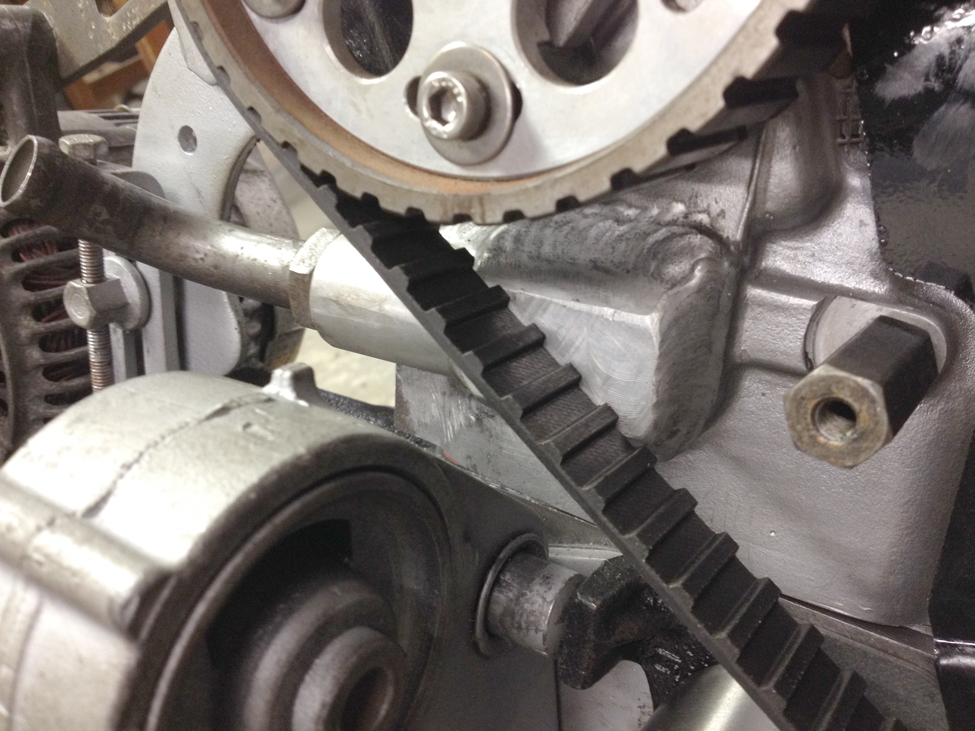
Set the cam gear at neutral, and installed the belt ignore the belt stripe, the valley is what has to align, according to the manual.

Not that it really matters, however it would be nicer if MM set the dimple on the gear & hub to match the actual marker alignment position..


Pointer is only slightly retarded - less than with shaved head, so I just moved the cam up a few degrees from neutral. Perhaps less advance than I had previously, certainly less than when I checked valve/piston clearance- which means I should have a little more clearance than the previous .072"

Locked the flywheel & torqued the gears and tensioner to spec.

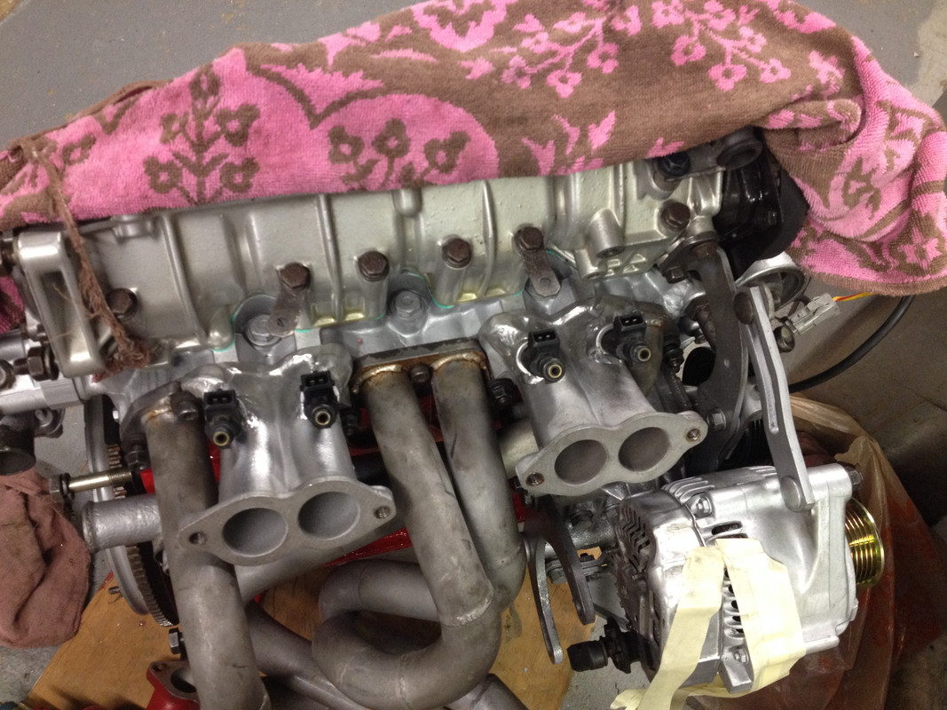
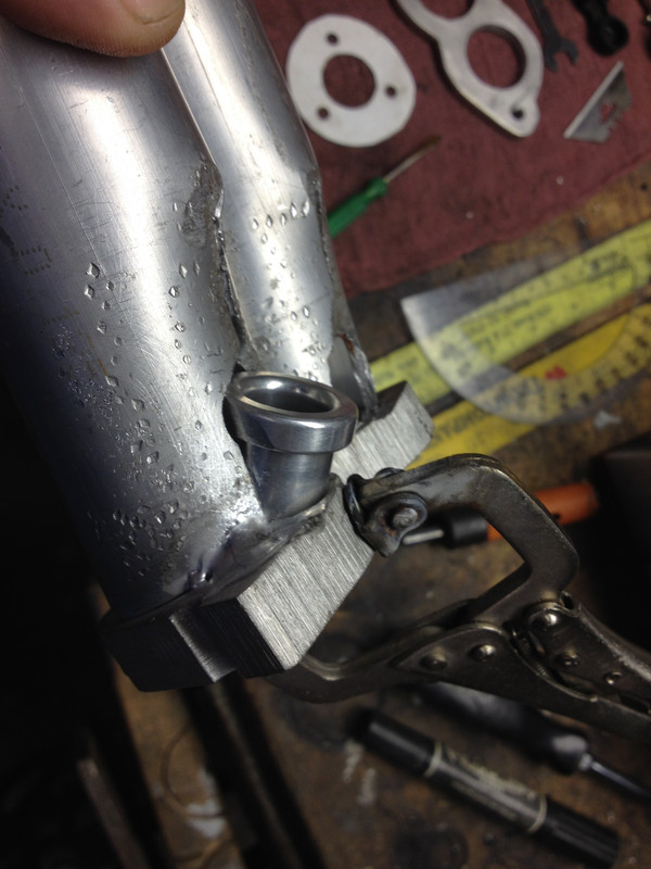
Coming along slowly - t/stat extension & housing on

Anyone have a pic of where that black steel belt sheild is supposed to go (laying on my plastic cover)? For the life if me, I can't see it

AC clutch arrived this evening, so I'll check the overall fit of the completed serpentine setup. Belt is supposed to be here tomorrow.
 
Last edited:
Worked on the wiring harness. I used a LH2.4 harness, removed the fuel connector & rewired/repinned using the EZK connector - since that matches the older LH2.2 ECU connector (25pin).

IMG_3537_zps9379c949.jpg


Note:- 14 is on the right.

X19-LH22-00027.jpg


X19-LH22-00025.jpg


Took out the X1/9 L-Jet harness, so I could start comparing. Volvo Harness is way too long - so I started cutting it down, component connector by component connector.

Just have to get the injector and TPS connectors and main ground connections placed, then it'll be ready.

X19-LH22-00029.jpg
 
Last edited:
Harness is almost done just have the injector lines sorted. Added integrated wiring for the heater valve controller, oil pressure gauge, oil cooler fan, O2 and idle speed control circuits.

IMG_3550_zps0d11c66c.jpg
 
Scrapped the custom runners - too complicated to get all the angles/planes set up correctly.

Modified the stock runners instead.

X19-LH22-00035.jpg


Spacing is 55mm on center for injector pairs, and 135mm between pairs. Having a honda rail re drilled for this spacing. It will be a regulated pressure at the rail only setup, similar to my 98 Volvo. So, I will be installing the regulator over where the filter is, with the return in the same location. Much cleaner install. Lines will be 5/16 sheathed plastic line (from a Volvo, of course) with Quick Connect couplings for the pump output, filter and return. Legal pad drawings to follow.

X19-LH22-00042.jpg


X19-LH22-00041.jpg
 
Last edited:
Back
Top