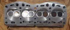
Milling head on 1500cc engine

I don't mean to detract from this thread, but I'd like to continue the question about the stock compression ratio if Beezee doesn't mind.

I'll wait to see if Steve C responds with more info on his experience actually measuring a US spec head. But has anyone else actually done it? I mean CC'd a head chamber, taken all the measurements, and done the calculations as Steve outlined for the Euro spec head? This would confirm the actual stock compression ratio. We already have some debate about the factory's claimed 8.5. It would be great to confirm things either way. As mentioned, it matter more in my case for the intended type of engine build. Thanks
Is there anything we can learn by comparing expected static compression test numbers for the 1500 to other engines in the 8.5:1 compression ratio range? I think a US 1500 in good condition is supposed to be in the 150 - 160 psi range. I checked the numbers for my T5R which also has an 8.5:1 compression ratio. It specifies 156 to 185 psi for compression test results so it does overlap with the 1500 numbers. They are two very different engines, the T5R being a 2.3L 4 valve turbo. The non turbo Volvo motor has 10:1 compression ratio with an expected compression test result of 185 to 213 psi. It might be interesting to plot a number of engines and see if there is reasonable correlation although I'm not sure we'll be able to tell an 8:1 motor from an 8.5:1 unless the distributions are pretty tight.
 
It will be fun to see what comes of that. But are there other factors that will contaminate the data with that approach? Condition of each engine's rings, valves, etc. Or the factory's designed amount of blow by or other losses for whatever reason. Or for that matter, how accurate are their claimed compression ratios? Not sure if dynamic compression vs static plays into this any (don't think so).

I'd have guessed that someone on Xweb has actually measured/calculated the stock compression ratio of the engine after all these years of doing so much to them. o_O Especially all the X1/9 racers out there.
Wish I still had some of my old lab equipment; I have a head sitting on the bench I could CC. I think from there the rest of the dimensions needed for the calculations are already known(?). Mark said he had done this before, has anyone else? Or does anyone have the equipment to measure combustion chamber CC with? If they want to send it to me, I'll do the measurement and send the gear back. In the meantime I will open a new thread with the specific title of CR, to see if it attracts more input (maybe someone that has the data will see that more easily).
 
other factors that will contaminate the data with that approach? Not sure if dynamic compression vs static plays into this any (don't think so).

It sure does, in fact a cranking compression test is more a measure of the engines dynamic CR than it is even close to being a measure of the engines static CR. A long duration or long overlap cam will seriously alter cranling compression values by large amounts... even small variance in settings like the lash adjustment (which alters the valve timing effectively) will give a variance in readings across an engine..let alone variance in equipment/method.

I'd have guessed that someone on Xweb has actually measured/calculated the stock compression ratio of the engine after all these years of doing so much to them. o_O Especially all the X1/9 racers out there.

we racers are not so much worried about what the static CR was, but far more interested in what we can achieve (i.e. higher static CR) with parts mixing and matching...

If anyone does have a number, it will only ever be a "nominal" figure anyway...each head will be slightly different and half a cc makes a difference...so the ONLY true way to ever know the ACTUAL static CR is by direct measurement of the particular engine involved... no other way, that's it.

The figure of 33.5 +-0.5cc for a Flat faced euro style head is quite constant... we know that some US spec heads are actually the same casting number as a head we get here in Australia (so same casting number in both flat and full circular decompression recess style heads) we know the recess is approx 1.5mm deep from the head face when the head is new, we also know the cut isn't flat on the bottom...it's is a section of a sphere (as can be seen by the remnants of these in JimD's pic of the MWB head) which I have never been able to accurately determine it's depth...

so a 1.5mm deep recess is approx 7.5cc, but we cant just add this to the 33.5 number...as the two sections intersect and share common volume. a good guess would be approx 4 to 5 cc is added by the full circular decompression recess in the US spec heads.

And then add to my calculation (which was sort of assuming the piston crown sat at zero deck when at TDC) the distance down the bore the stock piston sits...I have only been able to measure australian spec engines, and these sit shy of the stock deck by approx 0.35mm...the pistons measure with a CH of 34.65mm (zero deck on a stock block is generally about 35.0mm)

Now according to Fiat parts literature the USA spec piston crown are actually a CH of 34.45.... which goes with anecdotal evidence I have read / heard that the USA spec engines have the pistons sitting 0.5mm / 20 thou below the deck...which sounds about right with a piston of 34.5ishmm of CH.

anyway add in the volume the piston is shy of zero deck, ring land clearance etc and your going to be up around that 53cc of total volume above the piston at TDC... so I stand by my "educated guesstimate" of 8.1:1 being far more accurate than 8.5:1 ever was .... but if all the clearances stacked up (i.e valves less recessed in seats, combustion chamber cuts at minimum, deck cut at maximum tolerance (low) ...i.e. all the things that could possibly make the volume smaller, so the very smallest volume possible with a combination of all variables...then you might have 8.5:1 as an absolute maximum.

SteveC
 
so I stand by my "educated guesstimate" of 8.1:1 being far more accurate than 8.5:1 ever was
Steve, thank you very much for the added explanation. That is what I was wondering and appreciate your taking the time to answer.

I started a new thread asking if anyone has performed the actual measurements and calculated the CR for their stock US spec engine. We'll see if that brings any more info to the table. Otherwise I'd like to do the measurements to my engine if I can come up with the appratitus. Short of that, I suppose for my needs I might be safe in using a number somewhere in between the 8.1 and 8.5. Basically I'm looking the determine a good choice of head gasket thickness, to purchase a MLS gasket for the turbo build. Not that I need to meet an exact specific CR target, but more to make sure I don't exceed what I think will be safe. So a little error on the side of caution could be used, although I'd really hate to give up more than necessary. ;)
 
So it seems I've misled everyone as there was a mistake in my calculations as pointed out by an esteemed member via PM. I calculated CR based on swept volume/combustion chamber volume. This is wrong. It is actually (swept volume + combustion chamber volume) / combustion chamber volume.

Plugging in my original numbers:

Combustion chamber = swept volume/CR - 1
Combustion chamber = 374.64 / 8.5 - 1
Combustion chamber = 50 cc

So to achieve 10:1, the combustion chamber must be reduced to 41.6 cc, a difference of 8.4 cc.

The area of the recess is 59.45 sq cm, so 8.4 / 59.45 = .14 cm (1.4mm) = 0.055" (my original calculation was 0.044").

Once again, this assumes a CR of 8.5:1.

Brian
 
As a datapoint (this is from memory of about 10 years ago) I milled .060 off my '86 1500 head, and then did all the measurements and calculations to see where I ended up. It was somewhere in the 9.7x:1 range. I didn't dare take any more off the head, so I could not get to my goal of 10:1. My initial calculations were based on the idea that the engine was actually 8.5:1, but as my post-modification measurements showed, it could not have been that high to begin with.

Pete
 
I got the head back from the machine shop today. The head was machined just enough to remove the recesses:

Milled head 001C.jpg


I will be measuring the combustion chamber volume to get a real compression ratio number.

Brian
 
I will be measuring the combustion chamber volume to get a real compression ratio number.
Brian, did you ever get a chance to do actual measurements on this? I've still never found any real measurements to verify the stock compression ratio. My other thread asking the question went unanswered, so I assume it has not been done. Unfortunately I don't have the proper equipment to correctly measure the combustion chambers on any of my heads (which are now off the engines). Maybe if you happened to measure your milled head, knowing the amount that was milled, you could determine what the stock ration was before hand? Thanks
 
Brian, did you ever get a chance to do actual measurements on this? I've still never found any real measurements to verify the stock compression ratio. My other thread asking the question went unanswered, so I assume it has not been done. Unfortunately I don't have the proper equipment to correctly measure the combustion chambers on any of my heads (which are now off the engines). Maybe if you happened to measure your milled head, knowing the amount that was milled, you could determine what the stock ration was before hand? Thanks

I haven't worked on the head in quite a while and the way things are right now, it looks like it will be a winter job. In addition, my car has been running fantastic this summer so I am a little reluctant to start messing with it.

Brian
 
I recently bought half a dozen NOS compete USA spec 1500 heads, so for the first time ever I have a brand new unskimmed full circular recess head to measure the depth of the cut.

It is well over 2mm deep, almost 2.5mm deep in fact as the base isn't flat as I mentioned in other posts, so to completely remove the recess would be very close to / or even slightly more than 100 thou off the head (2.5mm) from new.

When I get a chance to CC the chamber I'll post the result, but don't hold your breath...not too high on my list of priorities
20210418_140509.jpg20210418_140133.jpg

SteveC
 
Back
Top