"My" ideal header

rjplenter

True Classic
I know this thread started on the discussion forum, but I thought I would move it here.

According to the book we were discussing, Four Stroke Performance Tuning (which like any publication, you can take or leave), for my 1300cc engine running a camshaft that opens the exhaust valve 80 degrees BTDC and with a desired peak power at 6,000rpm, I would prefer:

4-2-1 system,
First pipes (from head) 1.25" O.D., and 15" long,
Second pipes, 1.65" O.D., and 18.8" long (this includes length of the first collector),
Third pipe (to entrance of muffler?) 1.8" O.D., 36.8" long.
All collectors would taper at 7-10 degrees.

The length of the third pipe is obviously pretty difficult with our little cars, so I would plan to use a muffler with as little restriction as possible and have the tail pipe terminate at that length.

If I wanted a bit more top end I would slightly lengthen the first pipes, and if I wanted a bit more mid-range I would shorten them. Either way, the total length of the first and second pipes and the collector would total 33.8".

If I were to chose a 4-1 system, the first pipes would be 33.8" long, the same diameter as above and join to 1.8" O.D., 36.8" long single pipe.

Cheers,

Rob
 
So now...

What's the plan to get that header?
A couple of other members have discussed having something made up (check with 'Kevin B', our administrator). Maybe if any of you guys do find a way to build / have one built, please consider the possibility of having a batch done...to sell to others here on Xweb.
Let us know how it goes. Thanks.
 
Hey Kevin,

Thats why I thought of you while reading Robs post. Sounds like he is developing the model from which to build them? This could be the best header ever offered for a street X.
 
Walt can build 'em. I'll offer up my car for "packaging" purposes.

Just let me know when we get to final dimensions.

Oh, and o2 bungs or not? ( I say yes cause you can always plug them if not using them.)
 
Wish list

O.K. here is my take on what to consider:

1) a 4-2-1 design with "street-tune" tube dimensions
2) stainless steel
3) heavy enough materials to avoid cracks / fatigue (but not overweight)
4) universal fit : 1300-1500, A/C - nonA/C, small alt - large alt, FI - Carb (O2 bung), Cat - nonCat
5) Flange that matches intake's thickness (for mounting and to avoid leaks)
6) and of course, not overly priced :)

Simple, huh? However, pretty much all of these criteria would not be that unrealistic to incorporate into the design. It seems that most (if not all) of the headers offered (past and present) have failed in most of these areas. So if something like this could be developed I believe there would be a market for it. Maybe even one of our faithful vendors might want to pick it up?
 
Last edited:
Rob, Kevin, et al...

As I'm sure you know, there are lots of suppliers that offer the components to help develop a header. Take a look at these examples:

http://www.mandrel-bends.com/catalo...-100/?osCsid=8fdac18d4a7fbba4768d50b7d68ab929

http://www.classictube.com/products/exhaust-tubes

http://www.burnsstainless.com/

At the latest SEMA show I met the owners of a small company that produces high-end exhaust items for other large companies. They are located in So Cal, very friendly and quite affordable to work with. I picked up a couple of custom formed items to make an exhaust for one of my vintage motorcycles from them. They would be another great resource for anything needed on this header project. Let me know if you think they could be of help and I will arrange it.
 
Another wish

Just in case I did not give enough criteria to include in the header design, here is one more.
7) At the distal end of the header (where it mounts to the rest of the exhaust) include either a "ball and socket mount" or a "flex tube" instead of the typical flange. This allows for better fitment of the exhaust system, alleviates vibration problems, and seals better.

http://www.jegs.com/i/JEGS+Performance+Products/555/30690/10002/-1

http://www.mandrel-bends.com/catalo...0-id-x-6-00-long-stainless-flex-tube-749.html
 
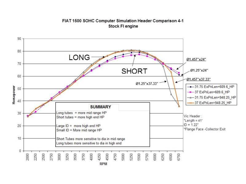
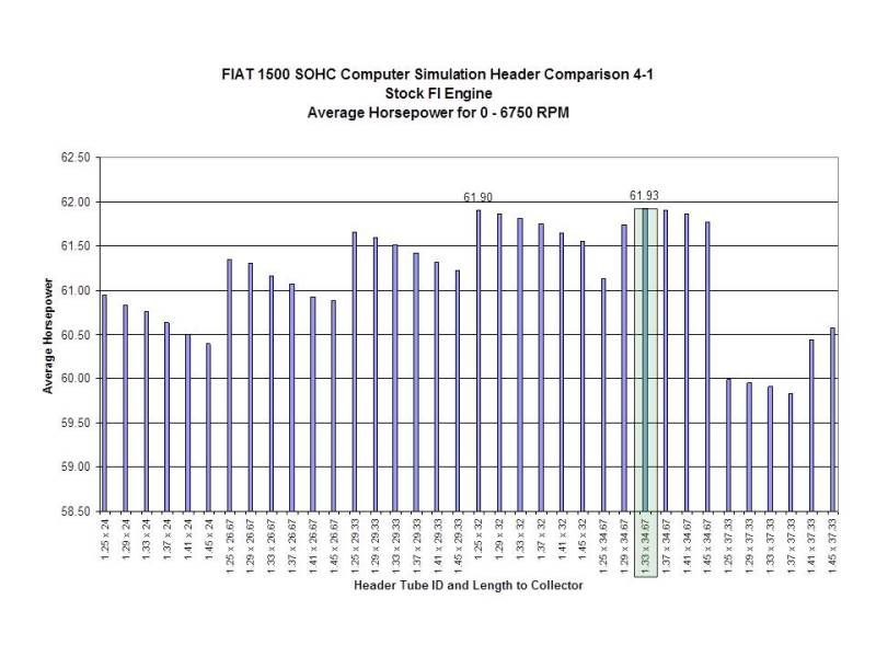
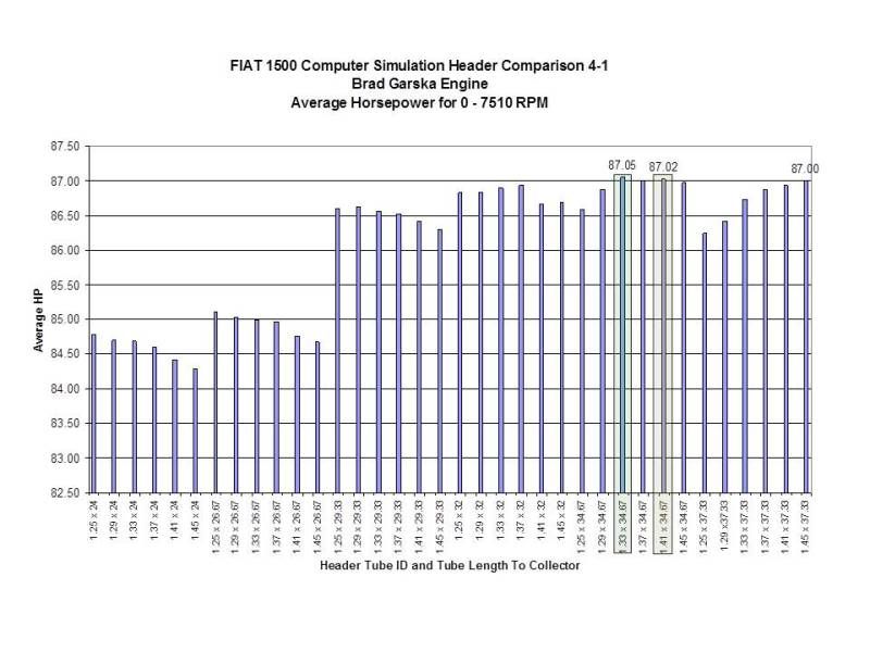
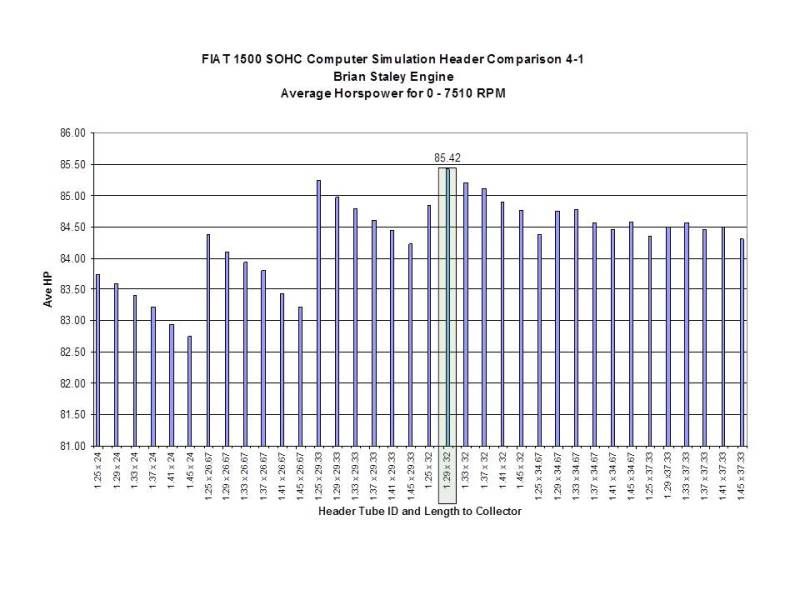
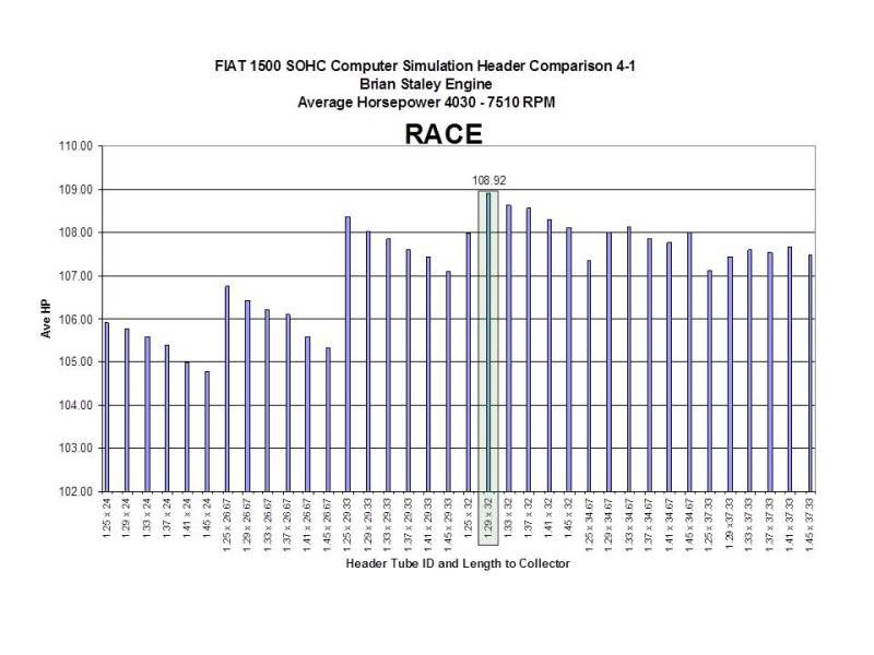
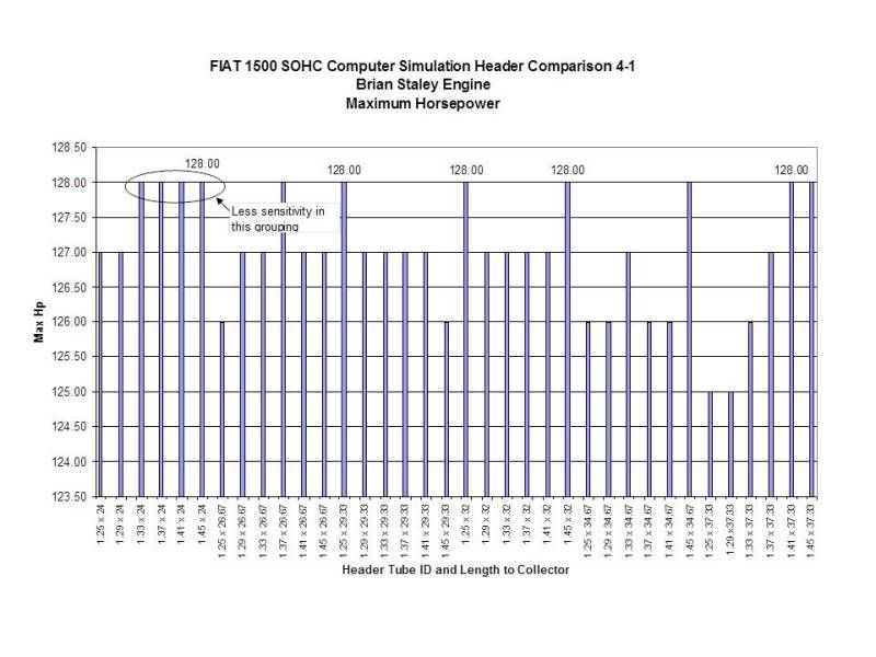
Here are some snaps from a 4-1 sim

Garska and I did this 4 or 5 years ago now and the summary was never complete but there are some good points. It was like 18 pages and the assumptions are based off of our engine set ups. Post is really just for grins. It would not take long to shoot holes in the info based on the assumptions etc but with that said the curves and results are not too far off.

Length is form flange face to collector exit.
Slide3.jpg

Slide5.jpg

Slide10.jpg

Slide15.jpg

Slide17.jpg

Slide18.jpg


I have not found a good 4-2-1 approximation calculation yet. The calculation is really not trivial too. To do it right you really need to do a chain calc that involves calculus and solving simultaneous equations.
 
Just to clarify

The figures I detailed were to match a 1,300cc engine, peak rpm of 6,000 and a 40/80 camshaft.
Although I found a mistake in my calculations, the third pipe diameter should have been 1.68", not 1.8"

If all other parameters remain the same, but you want this for a 1,500cc engine, the lengths remain the same, but the pipe O.D.s are now 1.35", 1.78" and 1.81".

The equations are based on the speed of a gas through a tube and the speed of the sound waves through a column of gas. As the positive pressure exits a pipe (going from four branches to two for example) a corresponding negative pressure wave travels back up the pipe and this can be used to scavenge more exhaust out of the cylinder. Therefore, as the timing of the opening of the exhaust valve varies, so do the dimensions of the pipes required. This obviously includes anyone using an adjustable cam drive and small advances in cam timing can yield small gains in performance.

Personally I think the 40/80 cam is a good choice for spirited road driving and I always like to keep the peak power rpm just below the redline. Also because I won't be competing in this car I would like a boost in mid-range torque and so desire a 4-2-1 system.

It would of course be impossibly expensive for any of our vendors to carry systems to match all variables, so even this exercise is going to require some compromise. Tube diameters will have to be approximated to what is commercially available. We need to maintain access to the manifold bolts/nuts. We have limited space in the engine compartment even without A/C.

Food for thought...

Cheers,

Rob
 
Header design

Thanks to DallaraX19 and Rob for posting some data. I agree with the comments about finding the best compromise for all of the design variables in tube dimension, etc. Some assumptions will need to be made. Perhaps a consensus can be reached from the Xweb members as to what combination of engine parameters should be used for the basis of the header design?

I'll give a couple of my thoughts:
I think there are far more road going (street driven) X's than track (race) driven, and it seems that the interest here is for a design that best fits this. So as Rob said, keeping the power band within the stock red-line limit with the peak boost in mid-range torque.

Cam selection (valve timing) may be a bit more difficult to decide upon. Maybe considering the recent thread discussing the best "road cam" may help?

http://xwebforums.com/forum/index.php?threads/16169/

Another difficult decision might be engine size. Seems like there are lots of 1300 and 1500 owners here. Any thoughts which direction to go? Can some type of effective compromise be made for both? If this only effects the tube diameter, then the decision may be made by the available sizes of tubing from which to make it (this will be a compromise from the 'ideal' calculated diameter).

Off the top of my head I do not recall the other parameters involved. I would have to re-read the materials. However some of you guys have a much better handle on this, so what do you say? Maybe SteveC has some valuable input as well?

Thanks again to everyone.
 
Last edited by a moderator:
Some further calculations

Firstly, thanks Dr. Jeff, after reading your link I think a 35/75 cam is better suited to my requirements.

Taking previous comments into account I have done some calculations based on set tube dimensions relative to camshaft profiles. The tube diameters quoted previously do not change, they are based on cylinder volumes. If we keep tube lengths the same (33.8"), and calculate peak RPMs based on camshafts, we get these numbers:

52 degrees 5360 rpm
68 degrees 5730 rpm
75 degrees 5890 rpm
78 degrees 5960 rpm
80 degrees 6005 rpm

If we shorten the tubes to 32.4":

52 degrees 5570 rpm
68 degrees 5950 rpm
75 degrees 6120 rpm
78 degrees 6190 rpm
80 degrees 6240 rpm

These correlate to a standard 12/52 camshaft and the others are those listed as street and hot street by one of our vendors. These numbers will also hold true for 1,500cc engines.

I was surprised by these results and they suggest that a one-size-fits-all system may actually work. We could actually devise a system that is suitable for 1,300 engines and another for 1,500 engines. Without having the dimensions of an IAP system (just by way of example) to hand, it is possible the the 4-1 tube lengths are compatible with several cam profiles and simply produce peak power at different RPMs. The caveat is they are potentially a compromise for engine capacity based on tube diameters.

So if I were to choose a 35/75 camshaft and 4-2-1 (1.25", 1.65", 1.68" O.D.s) system for my 1,300, total tube lengths of 32.4" would yield me a peak power at 6,120 rpm. And that would be good! :grin:
1,500cc engines would simply use the bigger tubes (1.35", 1.78", 1.81") and have peak power at exactly the same revs.

On the downside, a quick survey of available tubing diameters reveals 1.25", 1.375", 1.625". 1.75" and 1.875" sizes. So I would suggest perhaps:
1,300cc: 1.25", 1.625", 1.75"
1,500cc: 1.375", 1.75", 1.875"

Cheers,

Rob
 
Tube diameters

Rob,
I agree that the 35/75 cam sounds like the best choice for the street. It is my understanding this is very close to the profile used in the "Euro spec engine"; with it's improved manifolds, head design, etc, that engine was far superior to the US spec unit. And the improvements commonly done to our engines (improved flow, higher compression, increased induction) results in a combination very close to that Euro spec engine.

Based on past experiences, when having something like this header custom built, it is generally much more cost effective to have say 40 of them made all the same, as compared to having 20 made to one spec and 20 to another spec. Also, unless everyone were to commit to ordering in advance, it may be difficult to know just how many "1300" units will be needed and how many "1500" units. So it might be advantageous to find a design that well suits both engines, and make only one configuration. Plus that way, if someone were to change engines later, they could still retain the best header ever made.

Without me actually going through the calculations, do I understand this correctly? If the same tube diameters were used on both the 1300 and 1500 engines, it would just move the "peak" of the power curve a little on one of them? For example, if the diameters that you specified for the 1300 yield a peak at 6120 RPM, where would those same diameters put the peak on a 1500? It sounds like it will be at a lower RPM, but how much lower? Because if it is not too much different, that actually could still be very satisfactory for a street car. Speaking for myself, I prefer a good mid-range power band over a 'peaky' one (depends on driving style, but most of the time in real-world driving my tach is less than red line). So I'm wondering if a 'one-size-fits-all' might work after all; a design that gets good results for both engines, one at slightly lower RPM's (or vise-versa) than the other.

Another suggestion. Now that you have calculated the 'ideal' diameters (for the 1300 and 1500) and found them to be slightly different from what is available in the tubes, can you run the calculations 'back wards' (so to speak) to see what you get using the actual diameters that are available (i.e change the variables in the equations to see what results you get with the actual tube sizes that are sold)? By doing this you may find that a particular set of diameters will yield a result that falls somewhere right in the middle of the ideal 1300 and ideal 1500. Again, making a good set up for both engines.

This is getting interesting, so keep playing with the numbers and see what else you come up. Thanks for your efforts.
 
Changing the pipe diameters...

...doesn't change peak power RPM, but it does change peak Torque RPM. Bigger diameters move the peak torque RPM up the range.

So we could make a system based on the 1,500cc dimensions and accept that for 1,300cc engines, the peak torque will be moved up some.
 
Design

Thanks Ulix for posting the discussion with Guy Croft. That helps to pull together this project and brings up another challenge, determining how to arrange the whole package so as to retain the desired tube dimensions and still fit the X.

Rob, regarding tube diameters and the power band. Thanks for correcting me about the effective change in 'torque' (vs HP), in my mind I was referring to 'torque' but I was simply saying 'power'.
I'm thinking possibly going the other direction with the tube selection; using the smaller diameters to bring the torque band lower in the RPM range, helping to balance the overall delivery, given the HP's band is closer to red line (as discussed). This would yield a broader total curve and give a more drivable engine. Naturally there is a limitation with what diameters are readily available, so choosing the tubes will be something of a compromise. Therefore try to find those sizes which best meet all of these considerations.

Thanks.
 
Thanks Uli

That was a very interesting read.

Jeff, I like your suggestion of going smaller. It will also help fit the pipes around our very tight manifold bolt access. And reading Guy's comments, will produce bends of a better diameter/bend radius ratios. It would also fit more neatly into the available pipe diameters.

So, I'll take one 4-2-1 system with pipe diameters of 1.25", 1.625", 1.75", primaries 15" long and secondaries (including collector length) of 18". I'll connect these to a turbo (or other low resistance) muffler with a 2.25" tailpipe. :dance2:
 
Building a model

Do any of you happen to have some type of CAD software to develop a layout of the header's design? Or maybe some drafting skills to draw up some ideas? The post from Guy Croft's site gives an idea of what is needed here.
Otherwise there is an optional way to work out a design. Several small-scale models (like 10:1 size) can be made using easily formed materials (e.g. coat hangers, soft plastic rods, pipe cleaners, ??). This allows lots of ideas to be tried and visualized.
Once an idea has been found that looks good (with software, on paper, or with the small models) a full-scale "mock-up" could be made to test fit it in the car. This mock-up is not a functioning unit, but merely something to see if everything clears. So it can be made from anything...cardboard, PVC, whatever. If a more realistic full-scale model is desired, then perhaps an old 'off-the-shelf' header could be cut up and cheap exhaust tubing sections added to create the overall shape desired. The actual diameter of the tubes may not be correct yet, but this is only a mock-up; it does not need to be pretty, just good enough to see if it will fit.
After the design is developed and found to fit well, it can then be duplicated by the pro's using stainless tubing of the correct diameters, lengths, etc (per the calculated specifications).
Unfortunately I am currently living away from my vehicles, so I'm not in any position to do this. But I hope someone can help out.
Thanks
 
For the mock-up

I've seen one done with PVC water/drain piping.
Yeah 3D desing software would be ideal, but they are expensive..
 
Back
Top