Need Coding/Arduino Controller Wiring Help

lookforjoe

True Classic
EDIT - Gen2 is entirely different than Gen1 shown in this post (link to later post)
I'm in the process of parts gathering for an AWD conversion on my Volvo C30. This was something I was considering down the road, however, a mint condition (besides the fact they just rolled it ) S40 AWD has come up, so that will be the donor for all the drivetrain parts I need, besides the manual AWD trans.

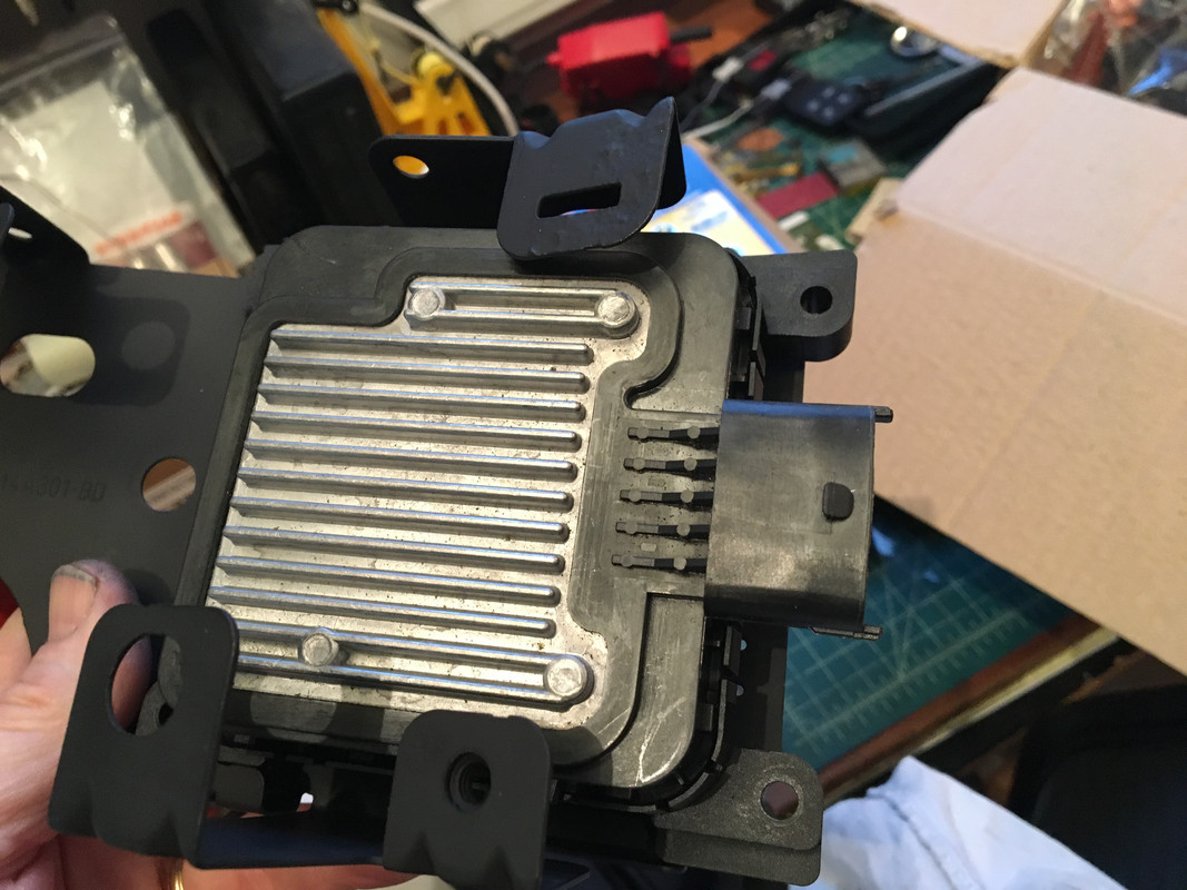
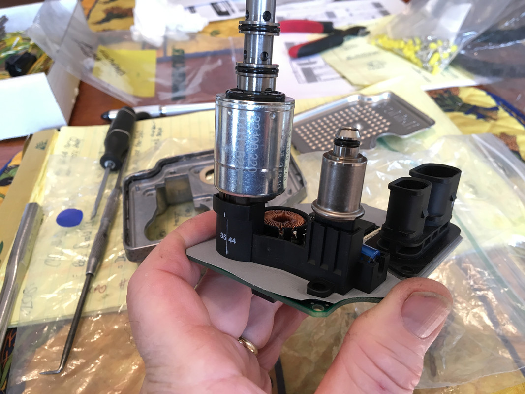
Anyhow, a major concern with the conversion is the Haldex controller. Some people have had success using a newer gen controller (3, vs. 2 that came with the S40/V50), others no so much. A work around that VW guys have developed is a manual controller. I need help with aspects of building the controller, and I know we have some tech-savy guys on here, I just don't recall who.

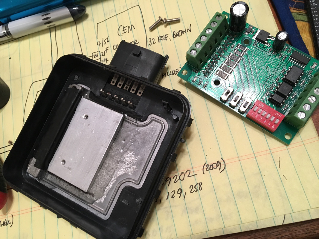
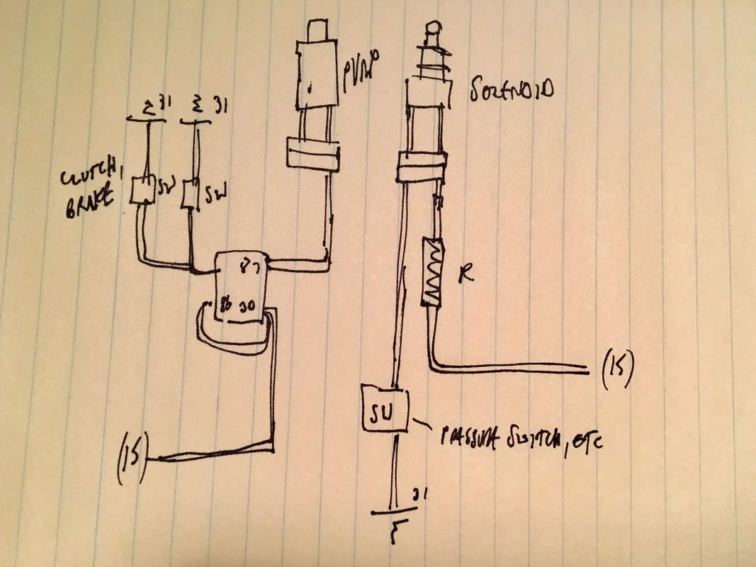
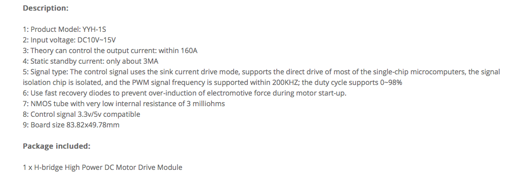
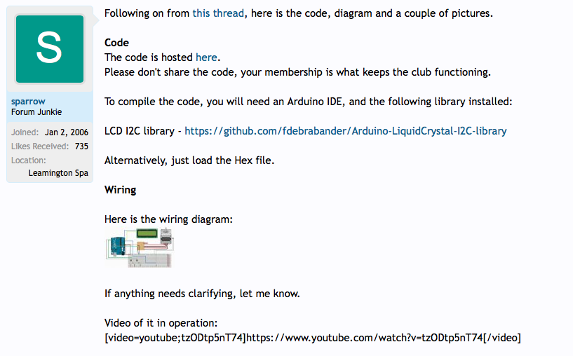
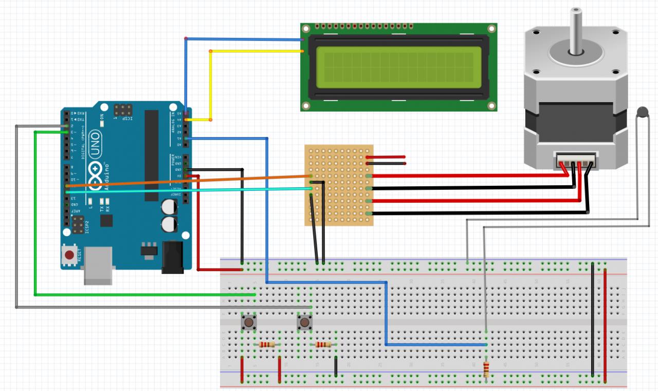
I can't post a link to the thread as it is closed/paid members only. I've added a screenshot of the post description of the Arduino/controller circuitry and a basic schematic.

I have no clue how to compile code, or how or where to load it, and they don't explain any of that - presumably assumption is one already knows that stuff. No one is active on that forum currently, so no one has replied to any of my requests for directions or clarification.

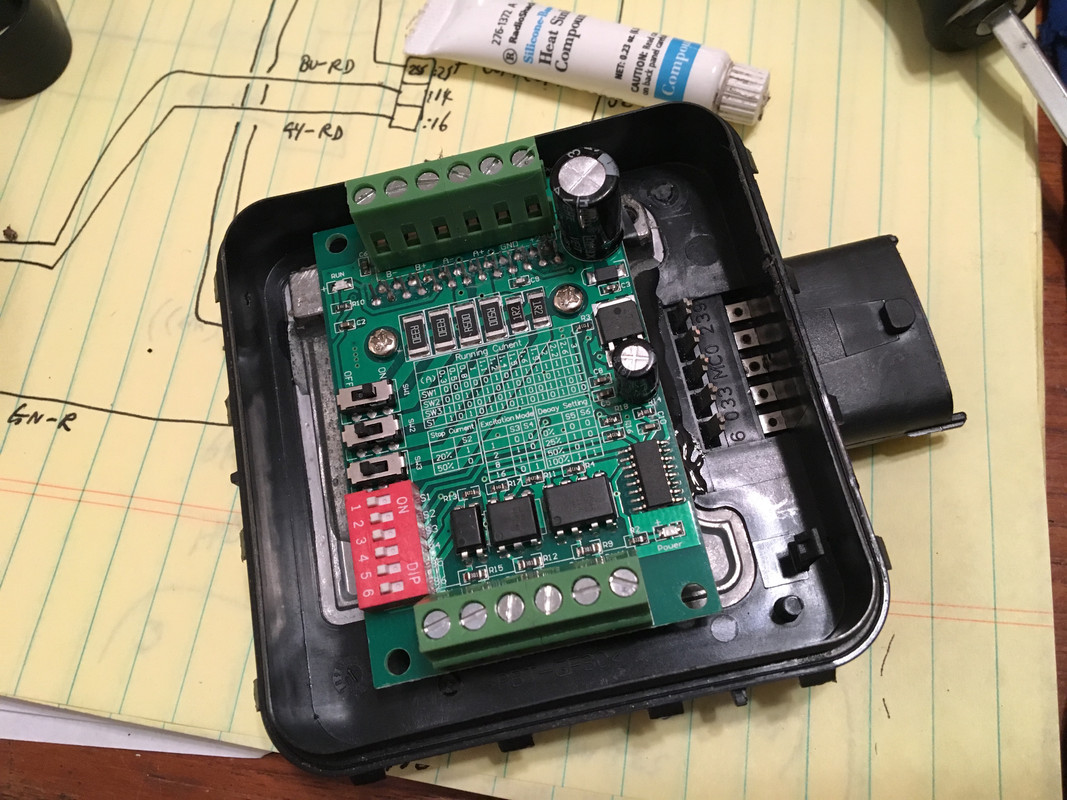
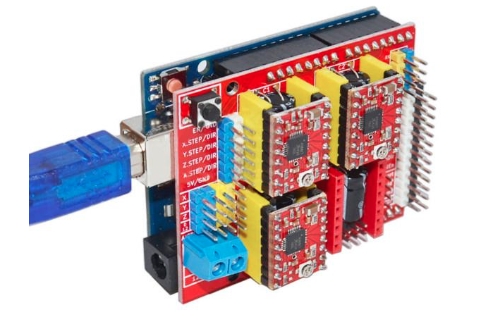
The wiring diagram is incomplete, and I can't tell for example how the stepper motor wiring ties into the Arduino via the PCB, since no connections are illustrated.

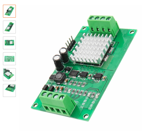
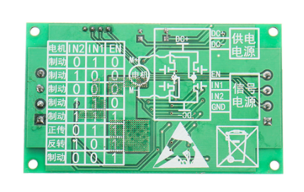
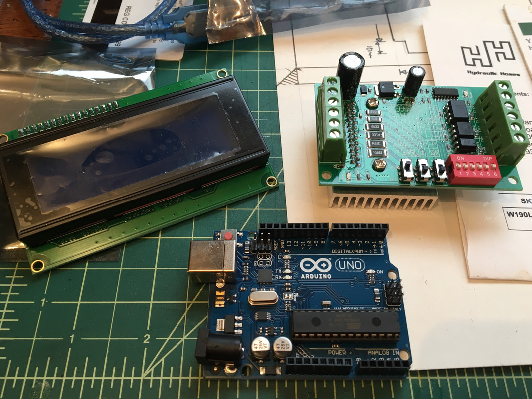
Three primary components are:

Arduino Uno, TB6560 3A, J204a display
IMG-7382.jpg


So, any help on basic directions for compiling/loading code, and thoughts on what makes sense regarding the actual control inputs from the PCB shown to the actual stepper motor.

Video of one being tested here:


and alternate here:


Thanks in advance for any input!

Screen-Shot-2018-12-26-at-8-46-40-AM.png


Schematic doesn't show TB6560 ?

Haldex-Board.jpg


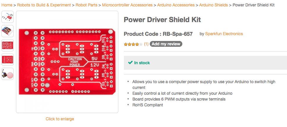
EDIT: Found this link for wiring Arduino to stepper controller

https://tronixlabs.com.au/news/tutorial-l298n-dual-motor-controller-module-2a-and-arduino/

and this, probably more useful, but I don't have stepper pin out

https://www.instructables.com/id/ARDUINO-UNO-TB6560-Stepper-motor-driver/

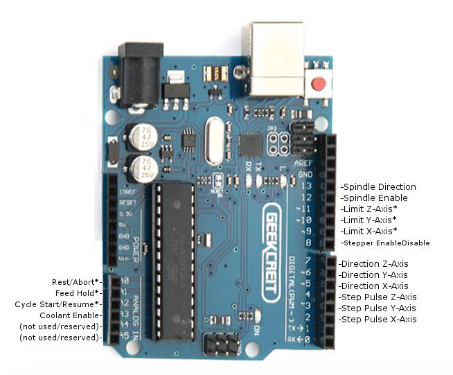
TB6560 Connection to arduino
pin 9 (Step pin) to CLK+,
pin 8 (Dir pin) to CW+,
CLK- and CW- connect to GND arduino.
Do not connect EN+ and EN- to any ARDUINO PIN.

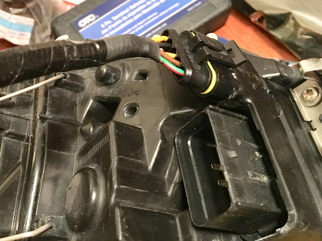
Stepper motor connection, you need to know which color is A+, A-, B+ and B-, according to the stepper motor spec. sheet.

Screen Shot 2019-02-21 at 10.19.47 PM.png
Screen Shot 2019-02-21 at 10.22.15 PM.png
 
Last edited:
I know nothing about this, sorry. But as you said, VW also used a Haldex system. You likely already know it has been discussed quite a bit on the Vortex forum, and that forum has specific topic areas - including for the all-wheel-drive system specifically:
https://forums.vwvortex.com/forumdisplay.php?742-Syncro-4motion-Quattro-Forum

Yeah. Those paricular guys seem to have more $$$$ on hand to throw at pre packaged controllers (HPA Motorsports) - nice to have available, for sure :D. Not applicable to the Volvo setup, even if I wanted to spend that kind of cash though. The GTI forum is where the home-brew stuff seems to be

https://www.clubgti.com/forums/inde...ldex-controller-taken-apart-with-pics.262986/

The components needed for a manual controller only amount to about $40, or so. It's just a question of knowing the procedure for working with these components that needs unravelling.
 
Unfortunately that was the only thing I know of regarding Haldex, so thought I'd throw it out in case you had not come across it. And sadly I know even less about Arduino. But it seems like a cool platform for all sorts of creative projects. Feel free to share some basic knowledge about it as you go through this, I'd love to learn more.
 
Unfortunately that was the only thing I know of regarding Haldex, so thought I'd throw it out in case you had not come across it. And sadly I know even less about Arduino. But it seems like a cool platform for all sorts of creative projects. Feel free to share some basic knowledge about it as you go through this, I'd love to learn more.

I appreciate the input. I will of course share stuff here. I have to, or I'll forget what I learn :D


Thank you, Bjorn!
 
Found a few wiring diagrams - gives me some direction. Some conflicting details

Screen Shot 2018-12-28 at 7.09.25 PM.png
Screen Shot 2018-12-28 at 7.10.59 PM.png
Screen Shot 2018-12-28 at 7.11.29 PM.png
Screen Shot 2018-12-28 at 7.15.15 PM.png
Screen Shot 2018-12-28 at 7.16.27 PM.png
 
Last edited:
Going to put the stepper motor inside a gutted fuel module. This bracket is already fitted in the right well, for a module related to the headlamp levelling system on some models, same form factor.

IMG-7891.jpg


Removed the stock circuit board, cut down the stepper motor heat sink, bonded it to the housing heat sink

IMG-7894.jpg


board in place. I have to either remove the connectors & reverse them, or solder the wires directly to the board. Planning on adding another connector, I think I need 10 wires for the stepper I/O

IMG-7895.jpg
 
Last edited:
Planning on adding another connector, I think I need 10 wires
As in retain the existing connector on the box and add a second one like it? That might be a little difficult but would make for a clean "stock" look. Or possibly fit a 10 pin connector of some type into the orifice of the existing box connector (after removing its guts)?
 
As in retain the existing connector on the box and add a second one like it? That might be a little difficult but would make for a clean "stock" look. Or possibly fit a 10 pin connector of some type into the orifice of the existing box connector (after removing its guts)?

The plan will be to cut an opening on the opposite end, in the lid, and bond in a connector like I did for my Morimoto E86 HID conversion, that way it looks clean.

IMG-7598.jpg
 
The dilemma I now have is I finally took my DEM out, and I don't have a stepper motor like anything pictured on the GTI forum. Mine (Gen II) has a "clutch control valve" (2 terminal) and a pressure/temp sensor (4 terminal). I don't see how I can make use of this setup to control it :(

IMG-7910.jpg


IMG-7908.jpg


Screen-Shot-2019-02-22-at-8-13-27-PM.png


Screen-Shot-2019-02-22-at-8-16-07-PM.png


Screen-Shot-2019-02-22-at-8-20-37-PM.png
 
Found this thread in the Swedespeed R forum.

Haldex Controller

Sounds promising. I'd still prefer to make my own....

Found someone else who looked into it - but never posted back ....

"For those of you that are not familiar with how the Haldex unit works, there is a solenoid valve that releases the fluid pressure from the clutch in order to allow certain amount of slip, this gives the ECU the ability to select the desired amount of torque to be transmitted to the rear wheels.

The valve can be manually operated quit easily, you just need to know its operation parameters, supply 3.2 volts and regulate the current to open or close it from 0.4 amp to 1.3 amp."
 
Are you looking to replace the ECU with a manual controller? Sorry, I haven't followed your other thread about it.

The factory setup doesn't always work on the AWD conversion - several members have reported. I just want a viable back up plan in the event the DEM (Haldex Controller) doesn't function as it should when my conversion takes place.
 
I know what you mean. Even when they are working right, I find that a lot of "programmed" control systems do not function the way I'd like them to. I guess the engineers design things according to what they think most people need, or what the attorneys dictate for liability reasons, or what government regulations require. None of which seems to fit me.
 
I know what you mean. Even when they are working right, I find that a lot of "programmed" control systems do not function the way I'd like them to. I guess the engineers design things according to what they think most people need, or what the attorneys dictate for liability reasons, or what government regulations require. None of which seems to fit me.

In this case, I'll be happy if it just works :D - As long as it does, niceties of engagement onset, torque split, etc., can be explored.
 
Directions for manual controller from VW forum:

Haldex Manual Controller
There are some steps you need o do to make it work:

1.- Find one pin that has continuity between the 8 pin connector and one of the terminals of the solenoid valve ( I don not remember 100% but I think it was the earth).

2.- Add a new wire from the other terminal of the solenoid to pin 6 that has no use on the module connector, now you are able to put any signal directly to the solenoid using this 2 pins, modify the harness for the controller or get a new connector to make your harness.

3.- Use a relay feed 12v to the Haldex pump take a signal that shuts off with the ignition switch, this way the pump will run constantly but will shut off whenever the car is off. If you wan to cut the current to the pump whenever the brakes are on, add another relay with signal from the brake light and that will stop the pump when you press the brake pedal.

4.- To feed the solenoid valve I just put 12v in series with the resistor to limit the current, the one in the picture is one of several that I tested you have to find the one that works right for you, use a current meter to find the resistor that keeps the current between 0.4 amp to 1.2 amp. This range is what determines the opening of the valve and thus the percentage of clutch slip 1.2 amp will put 100% lock on the clutch pack.

5.- Also using a boost switch (from a meth injection kit) to cut the current to the solenoid will allow you to turn the AWD on or off based on boost, as soon as the turbo is producing boost it send the signal to the solenoid. Currently mine is at 0.8 amp starting at 5 psi and works just find no wheel spin when using launch control.

I think you could use some sort of PWM signal instead, you just have to try different values to find the one that let you control the valve in a similar way. I think you could feed the solenoid using a resistor that limits the current to the max value, 1.2 amp will be the max current when you give it 100% PWM signal, also a high frequency may work to modulate it from 0% to 100% to keep the solenoid valve steady at the desired position you want.
 
Last edited:
Other ideas:

This is the basic wiring based on above description.

IMG-7954.jpg


Which doesn't explain how he regulates the solenoid travel, he only mentioned using a 10W resistor in series with the power supply to the solenoid, for about .8amp current draw.

Could I use something like this to control the valve?

H-Bridge DC motor driver PWM speed control

Screen-Shot-2019-02-27-at-5-36-51-PM.png


Screen-Shot-2019-02-27-at-5-38-15-PM.png


Screen-Shot-2019-02-27-at-5-35-22-PM.png


Or perhaps this to work with Arduino? Another Haldex DIY guy said I'd need a current shield for PWM.

Screen-Shot-2019-02-27-at-5-41-28-PM.png


Or repurpose a 3D printer x,y,z-axis stepper driver/arduino kit?

Some of them (as above) provide sample code to work with. As a noobie, I would definitely need help there :D

Screen-Shot-2019-02-27-at-5-53-35-PM.png


Screen-Shot-2019-02-27-at-5-54-08-PM.png
 
Last edited:
Other ideas:

This is the basic wiring based on above description.


Which doesn't explain how he regulates the solenoid travel, he only mentioned using a 10W resistor in series with the power supply to the solenoid, for about .8amp current draw.

Could I use something like this to control the valve?

H-Bridge DC motor driver PWM speed control

Screen-Shot-2019-02-27-at-5-36-51-PM.png


Screen-Shot-2019-02-27-at-5-38-15-PM.png


Or perhaps this to work with Arduino? Another Haldex DIY guy said I'd need a current shield for PWM.


Or repurpose a 3D printer x,y,z-axis stepper driver/arduino kit?

Some of them (as above) provide sample code to work with. As a noobie, I would definitely need help there :D

Screen-Shot-2019-02-27-at-5-53-35-PM.png
Interesting idea using an H bridge motor controller. That would give you the flexibility of changing the average current to whatever you want without changing hardware. The price looks good too. Also lower power consumption than cooking a resistor.
 
Back
Top