Need Coding/Arduino Controller Wiring Help

Interesting idea using an H bridge motor controller. That would give you the flexibility of changing the average current to whatever you want without changing hardware. The price looks good too. Also lower power consumption than cooking a resistor.

Started looking at Arduino projects with DC motors & L298N H bridges (like this) for understanding & ideas. It looks like a Pot. is the most obvious way of changing the average current? I'd like to figure out a way to set 3 switchable presets, which is basically what the other guys did with the original Gen I setup. Trying to figure out to add I/O features tied to driving conditions (braking, etc) that would interface with the programming(?) or hardware.
 
Still looking at options.

EDIT - Haldex circuit fuse is 10a (which includes loads from fuel filter relay, park assist, Bi-Xenon H/L)

This has higher capacity. Don't know if I need it, but since the pump runs 24/7, and the solenoid most of the time, perhaps it's safer to have more headroom? I'm thinking it's better NOT to have it attached directly to an Arduino, as that creates packaging / wiring problems in a car, esp. if I want it outside the cabin as intended. I may have to buy a few options & bench test them with a breakout board (I already bought one for testing the prior stepper motor layout anyway)

DROK L298 HBridge.png


This (Arduino) plug in board has DRV8825 drivers, which apparently perform better (2.8A) than the older chips. This would be intead of the board with 4998 drivers.


Screen Shot 2019-03-02 at 9.52.16 AM.png
 
Last edited:
Building more muscle I see, adding electronics and soon to be adding software development to your many skills. Thumbs up
 
Building more muscle I see, adding electronics and soon to be adding software development to your many skills. Thumbs up

Sadly, I won't remember what I have learned in a couple years. Unless it's something I end up using on a frequent basis, it's akin to cramming for an exam. I've built standalone ECU's in years past, and I can't remember one iota :D
 
After much deliberation, I ordered a few variations to play with, including 433mhz BT transmitter/reciever, and that would give me the option of reduced wiring in the cabin, sounds like a fun thing to experiment with, anyway :D

Screen Shot 2019-03-04 at 9.26.18 AM.png
 
Revisiting this as I still don't have the AWD fully functional. I can lock it using a test mode in VCDS, but otherwise no.

Trying to figure out the values I need to determine how to manually control it.

Solenoid closed, clutch locked

22-AWD-Clutch-Engaged.png


solenoid open, clutch open

22-AWDClutch-OFF.png


The VW guy said 1.2amp will lock the clutch, .4 amp allows slip. he also said "... supply 3.2 volts and regulate the current to open or close it from 0.4 amp to 1.3 amp."
Calculating resistance needed to achieve amperage range

Solenoid operation:

"Using the software parameters for the specific car, the electronic control module opens and closes the valve, which controls oil flow between the pump and the wet clutch pack. The valve opens when the module detects a loss of traction. The controller measures the amount of wheelspin (and resultant difference in rotational speed between front and rear wheels) and determines how far the valve opens and the amount of oil pressure applied to the wet clutch by the pump, which in turn dictates how much power is transferred to the rear wheels in each model. "
 
Last edited:
This is what was suggested to me on the Arduino forum - can anyone here interpret for me 🤪

Looks like PWM would be simpler?


A couple of possible ways to control it are linearly and with PWM.

In the linear model, you have an adjustable constant-current source like this (very crude):

yoOB9Dq.png


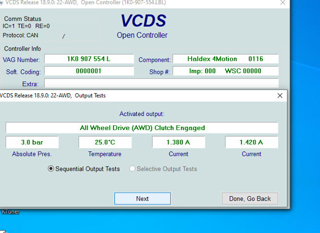
Suppose Rsense = 0.1-ohm. If you wanted 1.38A of current through the Haldex, you'd set up the Arduino to adjust the DAC to put 138mV on the '+' input of the opamp. The opamp will do what it can to get the difference between the '+' and '-' input to zero. Since the '+' terminal is higher than the '-' terminal, the output voltage will rise. This will turn on the transistor and current will start to flow. With current flowing in the Haldex solenoid (and thus Rsense), a voltage drop develops across Rsense. The top-side is connected to the '-' input of the opamp.

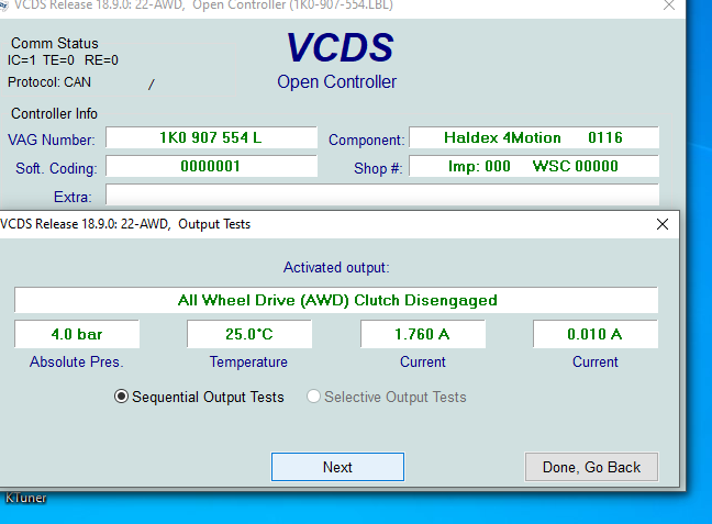
As the current reaches 1.38A the voltage seen at the opamp '-' pin approaches 138mV. At this point, the '+' and '-' pins are equal and the transistor will begin to shut off. But then the current will drop so the transistor will turn on again and so on. In this way, the system can give a pretty decent approximation of a constant current source. Its performance -- transient response, over/undershoot etc -- will depend on tuning things like Rfb and Cfb but it can be done.

Because the transistor is acting as a variable resistor here it is subject to power dissipation. A "ballast" resistor to drop the voltage passively will take away some of the heat from the pass transistor but things will still need some heatsinking to a metal enclosure.

The other way is to simply switch a low-side FET into saturation and off rapidly so that the average coil current in the Haldex solenoid approaches the desired current. The Pd in the FET is much lower since it's in saturation and the Rds on is very small. Assuming the switching frequency is fairly low switching losses will be pretty low too. You just need to characterize the solenoid's response to PWM, which may change over temperature (e.g.) To know the required frequency you'll probably just need to experiment; the inductance of the coil will matter here (--> time constant) but I think you'd be safe to start at, say, 30Hz and work up to 1kHz in search of the sweet spot.


Found this regarding the MOSFET - still greek to me - modes, channel type, etc

First, you need to define what type of Mosfet you are using. Is it depletion mode or enhanced mode? Is the mosfet channel P-type or N-type? I will assume you are asking about N-type, enhanced mode mosfets; although, in your previous question about battery charging you used an P-type, enhanced mode device.

"Low-side" means the current travels from the load or device through the mosfet to ground (common). "High-side" means the current travels from the supply through the mosfet to the load and then to ground.

Another way to put that is:
Low-side = mosfet source to ground, drain to load, load to supply.
 
Last edited:
Back
Top