Performing Honda K24a3/AST5 6spd Conversion

Hi Hussein. After a long absence from the forum, I just finished reading through this thread from the beginning. My hat is off to you for perseverance, in addition to your fabrication skills. Glad my build thread was useful for somethings. I will be eager to find out how your exhaust sounds as mine with the Magnaflow is too loud for my taste. I will be revising it in time but it will be a while. Keep up the great work and wonderful posts. Can’t wait for the start up.
 
Hi Hussein. After a long absence from the forum, I just finished reading through this thread from the beginning. My hat is off to you for perseverance, in addition to your fabrication skills. Glad my build thread was useful for somethings. I will be eager to find out how your exhaust sounds as mine with the Magnaflow is too loud for my taste. I will be revising it in time but it will be a while. Keep up the great work and wonderful posts. Can’t wait for the start up.

Thanks Rodger - your threads and assistance were invaluable :)

I ordered the SW chambered muffler. so I can build a separate setup with that & no resonator. I'll try the magnaflow first, since I have it. My experience with Magnaflow in general has been that they are on the loud side, some more tolerable than others.

I guess it's gonna be about a month before I get all the wiring done. I'm saving the best for last :D
 
I tend to be ok with a quieter car, if I am misbehaving (not that I ever do) I don’t want to announce the fact anymore than I have to :)

I would keep the resonator with the new exhaust set up to come.
 
I tend to be ok with a quieter car, if I am misbehaving (not that I ever do) I don’t want to announce the fact anymore than I have to :)

I would keep the resonator with the new exhaust set up to come.

I'm welding the resonator to the muffler. Not sure I'll want to cut it off & redo for the SW muffler :D

Finished the water passage outlet,

IMG-20191209-192642.jpg


drilled & tapped M14x1.5 & M10x1.5 for the coolant gauge and the coolant tank bleed. Leak-tested this one to make sure no seepage.

IMG-20191211-144924.jpg


Redid the sheath on the heater pipe after this pic, and reinstalled on car. Added coolant & it poured out the t/stat lower cap. Apparently the seal seat on this housing is different than the one I had in previously.

IMG-20191211-145045.jpg


Also noticed it was seeping around one of the bolts.

IMG-20191129-142926.jpg


Pulled it all out again, and found that when I did the time-serts, I cut through the housing wall, hence the leak. I've been making more work for myself each time I did this :D

IMG-20191211-180640.jpg


Anyway, I've wire-wheeled the inner ridge & JBwelded it all.
IMG-20191212-103916.jpg


This time, I'll assemble the the two housings, cap the ports & check the areas that have been a problem for leaks before I put it back on the engine..
 
Last edited:
Not to worry, we have been in the assembly process for a build at work and have found all kinds of little ‘oh my’ issues as we assemble these new solutions to something we worked on originally 20 years ago. Speaks to our products longevity.

Going fast and not getting feedback on the parts until weeks or months after fabricating them you will likely find some things you didn’t expect nor remember how you ended up with the issue.

As we say in product development, it is better to find out early in the process that you have an issue than after we are three months into development to find out and have a full reset. In your case that translates into finding the problem in your garage now and not next spring when you are far from home and you break something else as a result of a minor error.

Glad you were able to sleuth it out.
 
Took the housing with me to work, so I could leave it filled with water for leak testing :) No evidence of any seepage, so I put it back on the car after work. Waiting until tomorrow to add coolant, I have had varying reports on how long the HondaBond needs to set prior to exposure to liquids

IMG-20191212-071546.jpg


Water passage outlet back in place

IMG-20191212-145515.jpg


Started on welding sections of the exhaust - I removed the taper section & welded the two O2 bungs, and the flanges at each end.

IMG-20191212-163343.jpg


IMG-20191212-163354.jpg


Had a little time after that to set up the final hanger

IMG-20191212-171710.jpg


I'll remove another section of exhaust tomorrow & weld the next set of junctions. I may actually setup the water-cooled torch finally - it would be good for this work, as the torch gets pretty darn hot after welding more than a few inches of bead.
 
Last edited:
More work on the exhaust, after I filled the coolant (no more seepage) :)

IMG-20191213-150309.jpg


support/hanger pins finished

IMG-20191213-160801.jpg


IMG-20191213-164358.jpg


IMG-20191213-165045.jpg


Figuring out the header support with Honda bits - not sure if it will be OK on the side - no way to mount it in the middle underneath. EDIT - reading the support, if present, should be of the same material as the header. I'll have to make brace section out of Stainless to attach to the "L" bracket instead of the cast section

IMG-20191213-154648.jpg


IMG-20191213-154645.jpg
 
Last edited:
Worked on the heat shield / trunk floor framing today.

Started with this heat shield from the S40 AWD

IMG-20191214-113335.jpg


cut & folded to fit the opening, set upside-down here to use the opening to form the edges. Used the mallet to flatten the dimpled flanges, then pressed them bewtween two flats in the vice after this

IMG-20191214-115508.jpg


IMG-20191214-115938.jpg


Had to mull over what to do about the raised area - I decided to make a aluminum square tube frame to contain it, upon which the stainless steel floor pan will be attached.

IMG-20191214-163428.jpg


IMG-20191214-163459.jpg


air gap between the shield and panel

IMG-20191214-163656.jpg


two sections will be cut & welded as one

IMG-20191214-163645.jpg


The excess from the shield should be sufficient to make a panel between the exhaust bay & engine bay

IMG-20191214-163832.jpg


Whilst I was on a heatshield kick I cut the Honda manifold shield to fit the header

IMG-20191214-123404.jpg


cut edge was folded in on itself to keep the two- layer integrity
IMG-20191214-124515.jpg


Have to weld tabs back on the manifold flange, and one by the collector to support it

IMG-20191214-124202.jpg


IMG-20191214-124223.jpg
 
Wife is sick, feel like I'm getting sick also. Low energy, so I just futzed around for a bit. I did get the header support resolved though.

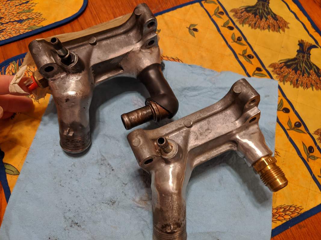
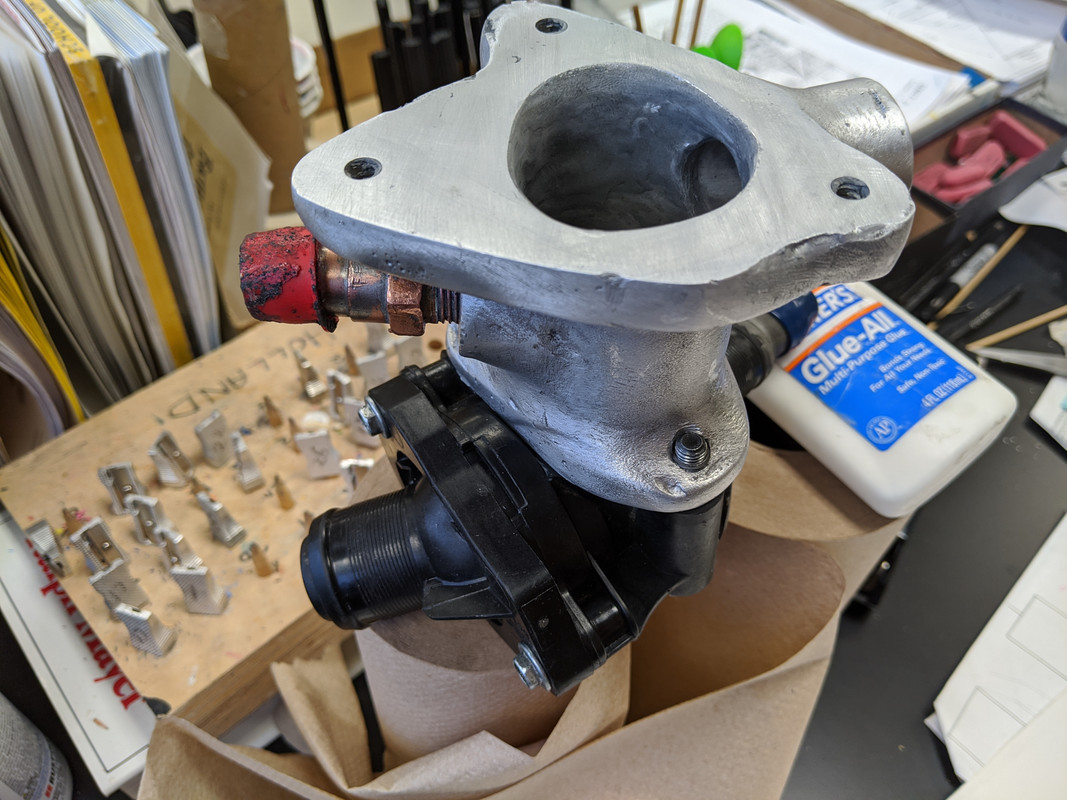
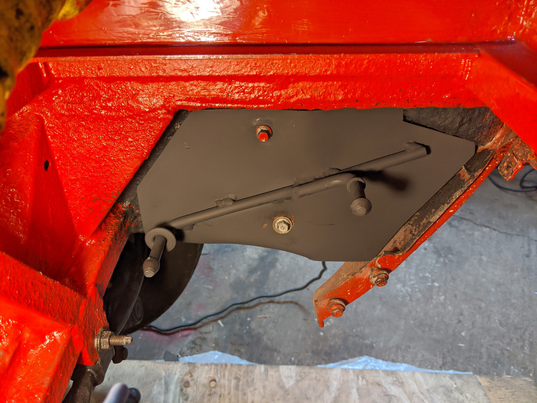
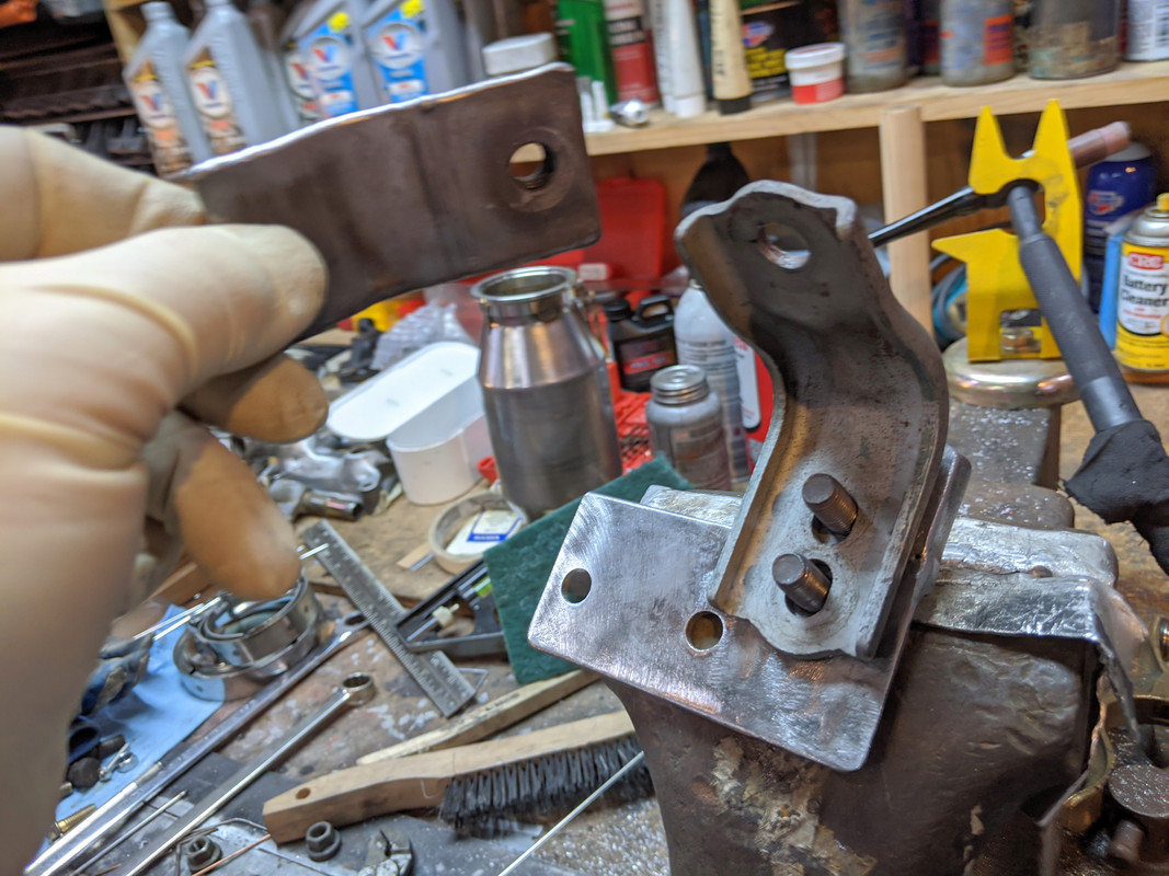
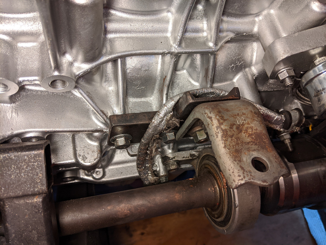
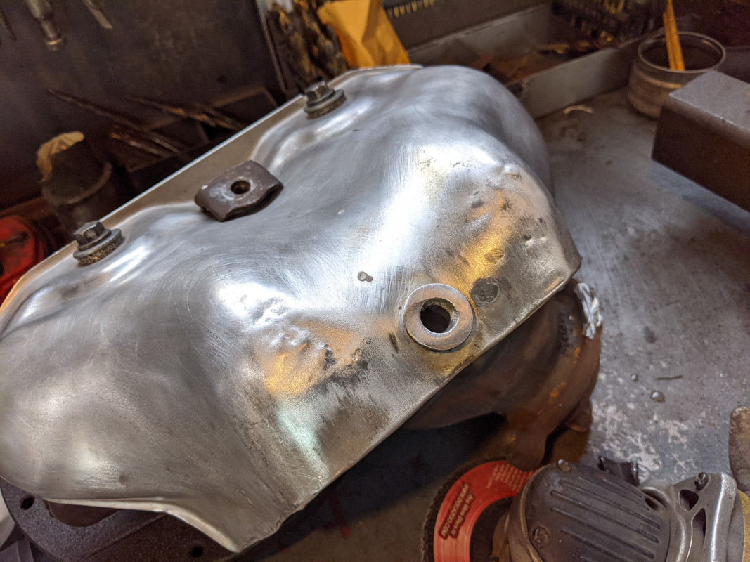
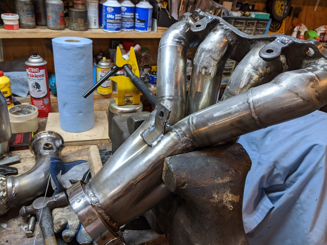
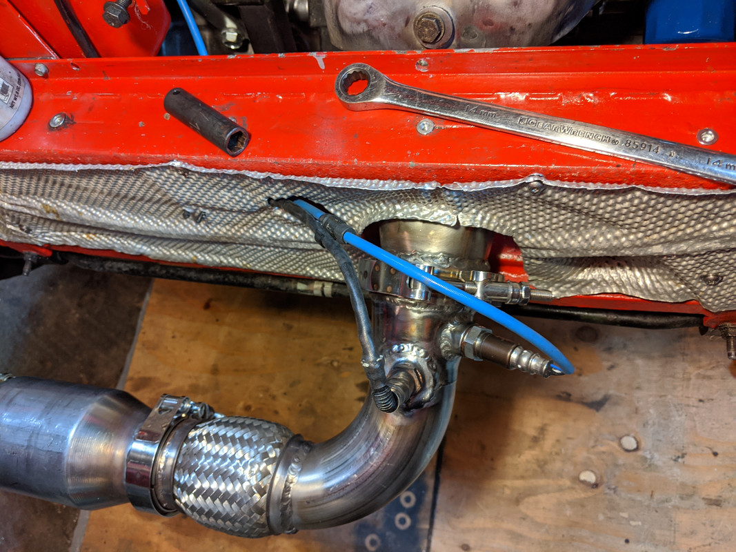
made a bracket that mounts underneath on the block - wasn't happy with the idea of a side brace. The factory elbow bolts to that, and then a SS tab will be welded to the header collector

IMG-20191215-101543.jpg


IMG-20191215-101614.jpg


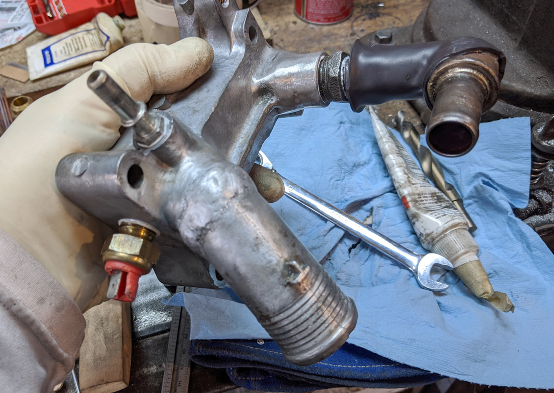
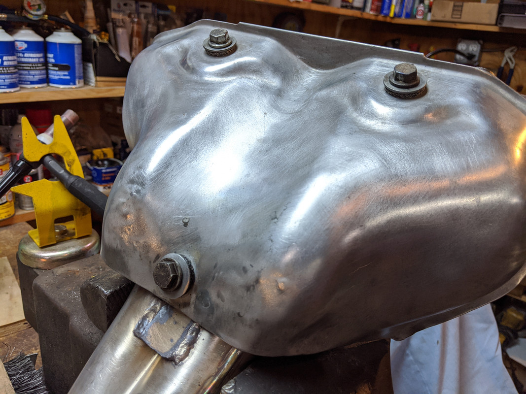
had to add a vertical section for the upper securing bolt of the elbow bracket. Bolts are welded on the backside.

IMG-20191215-112848.jpg


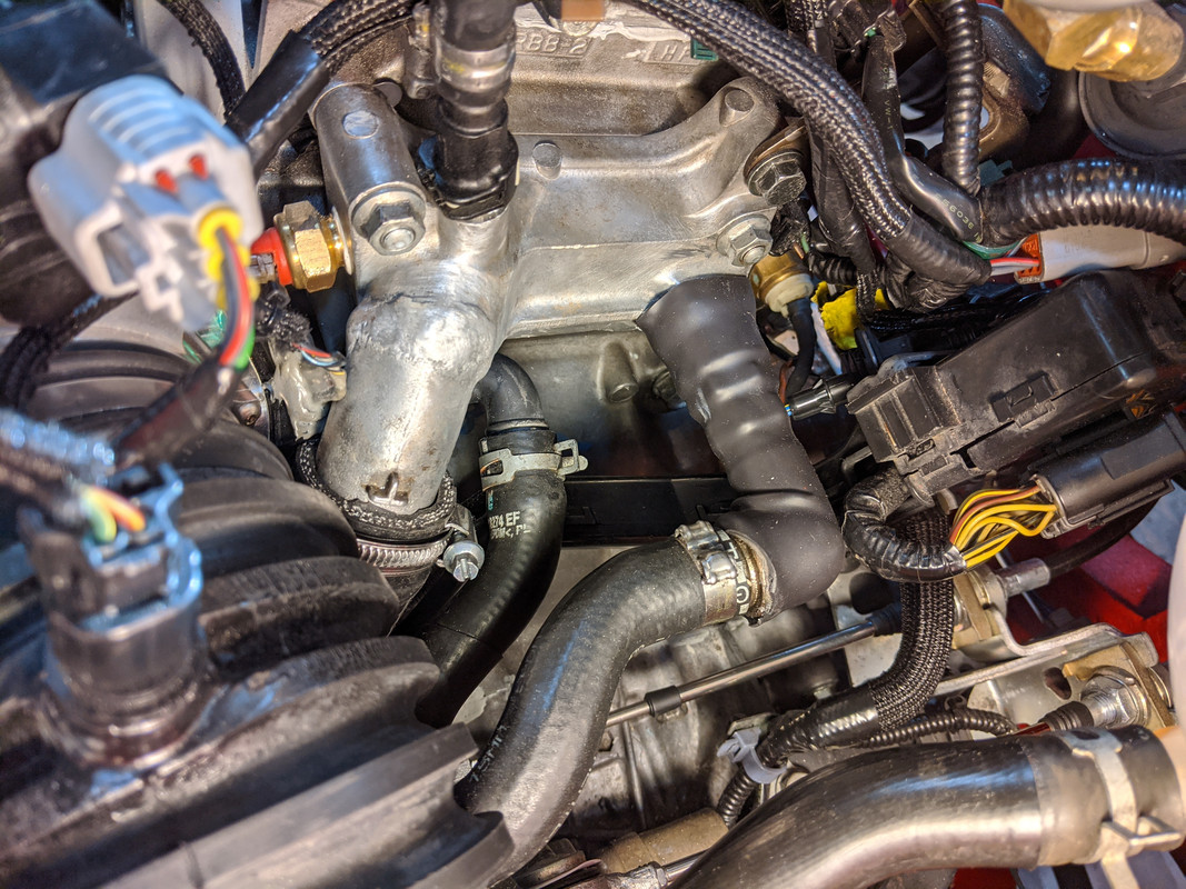
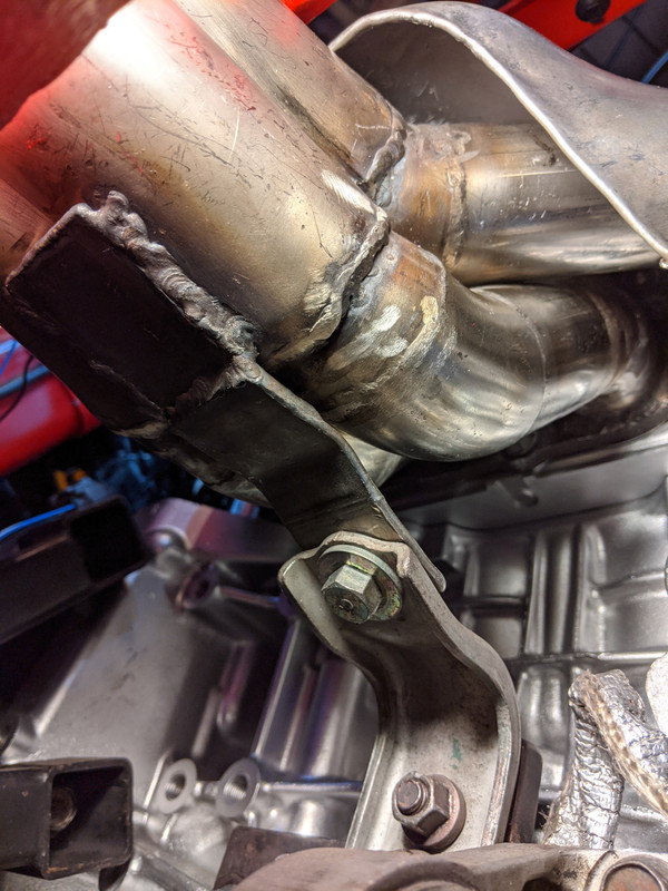
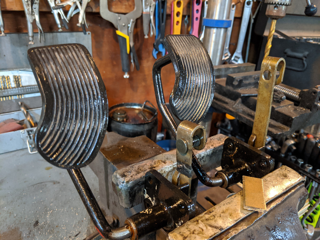
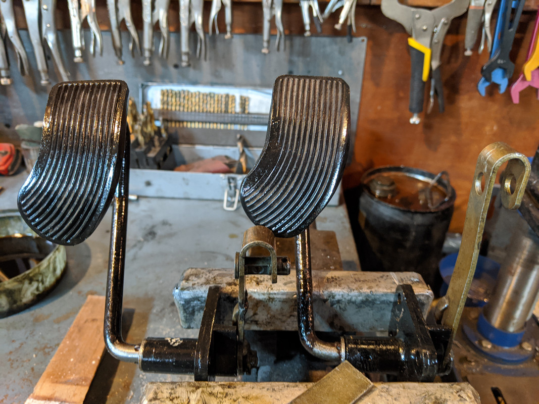
Honda bracket goes thus, with the header bracket on the other side

IMG-20191215-112926.jpg


All bolts are easy enough to access, nothing fiddly here

IMG-20191215-115414.jpg


IMG-20191215-121036.jpg


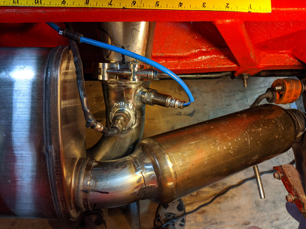
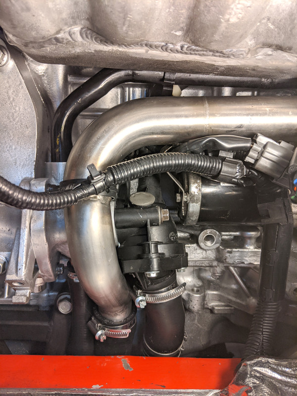
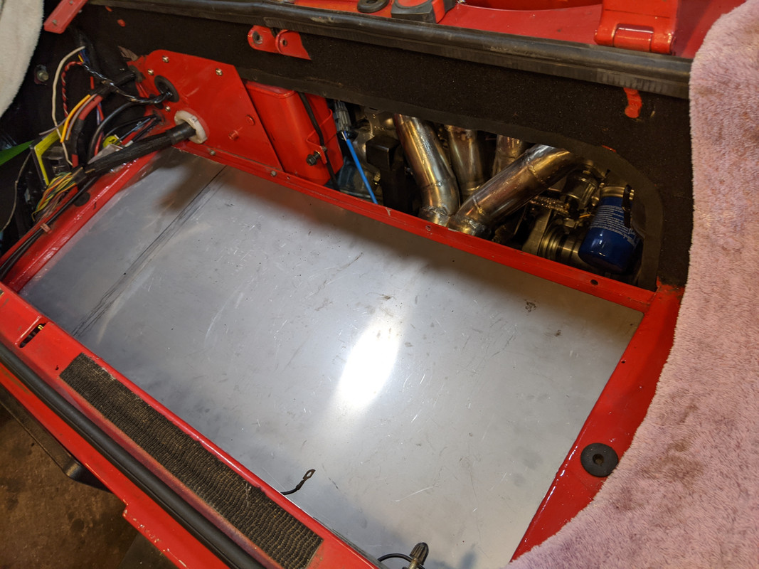
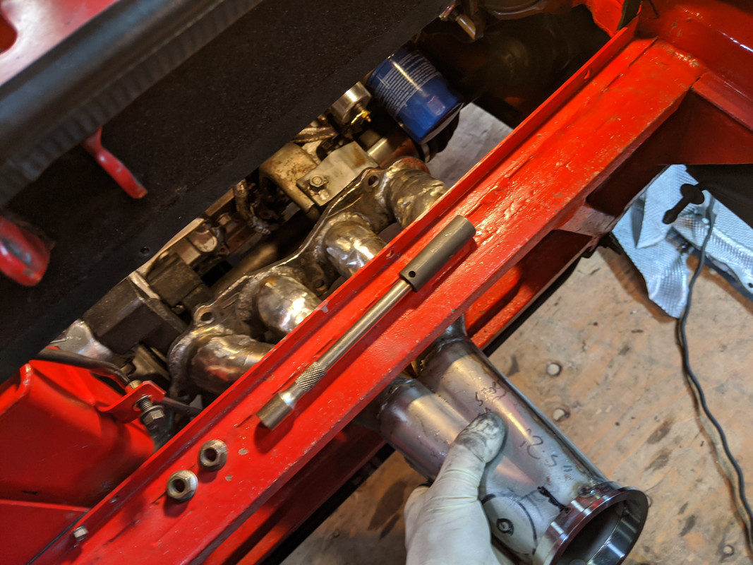
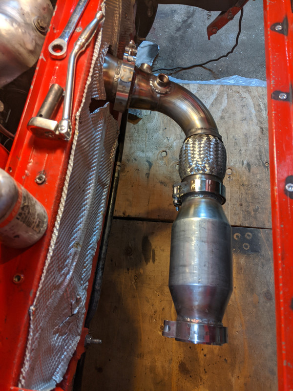
Header has to be installed through the exhaust bay....

IMG-20191215-120604.jpg


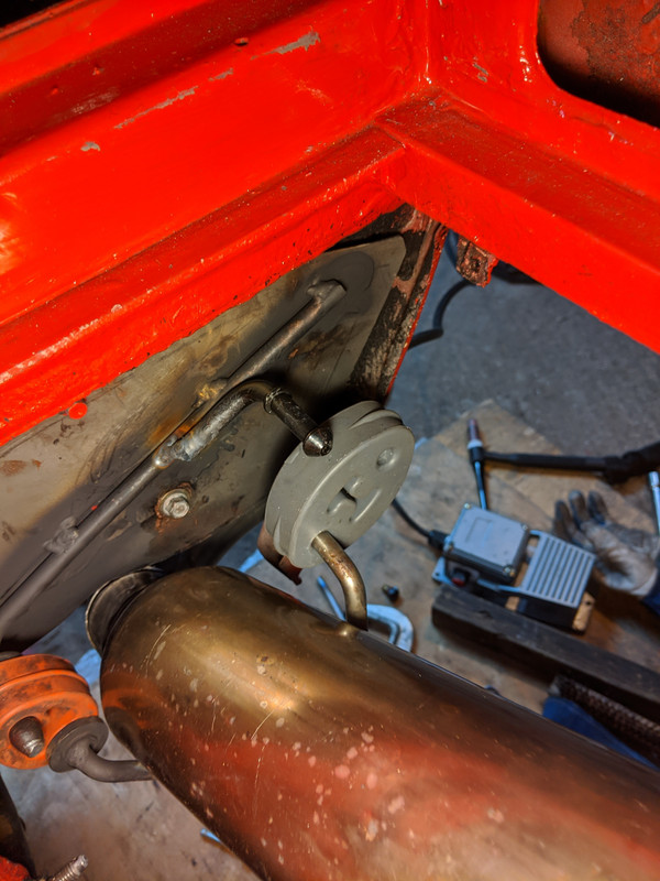
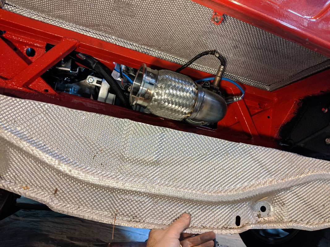
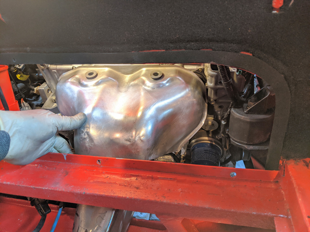
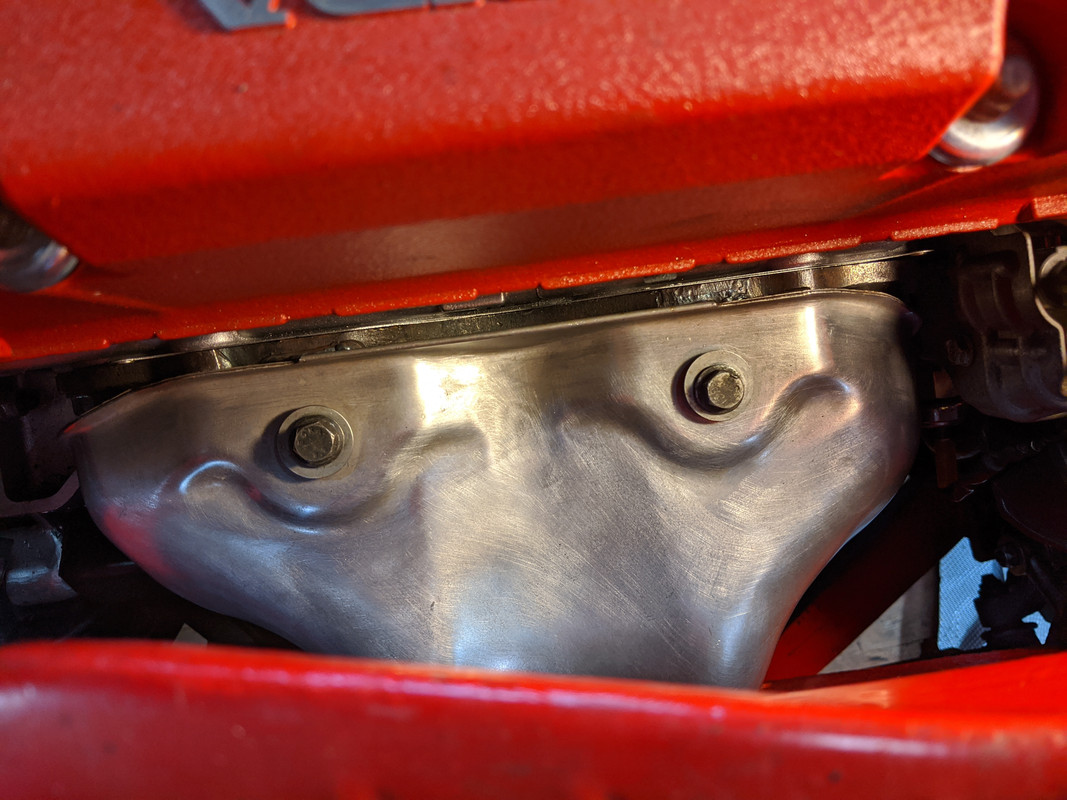
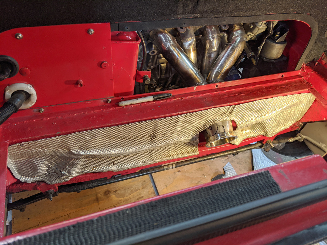
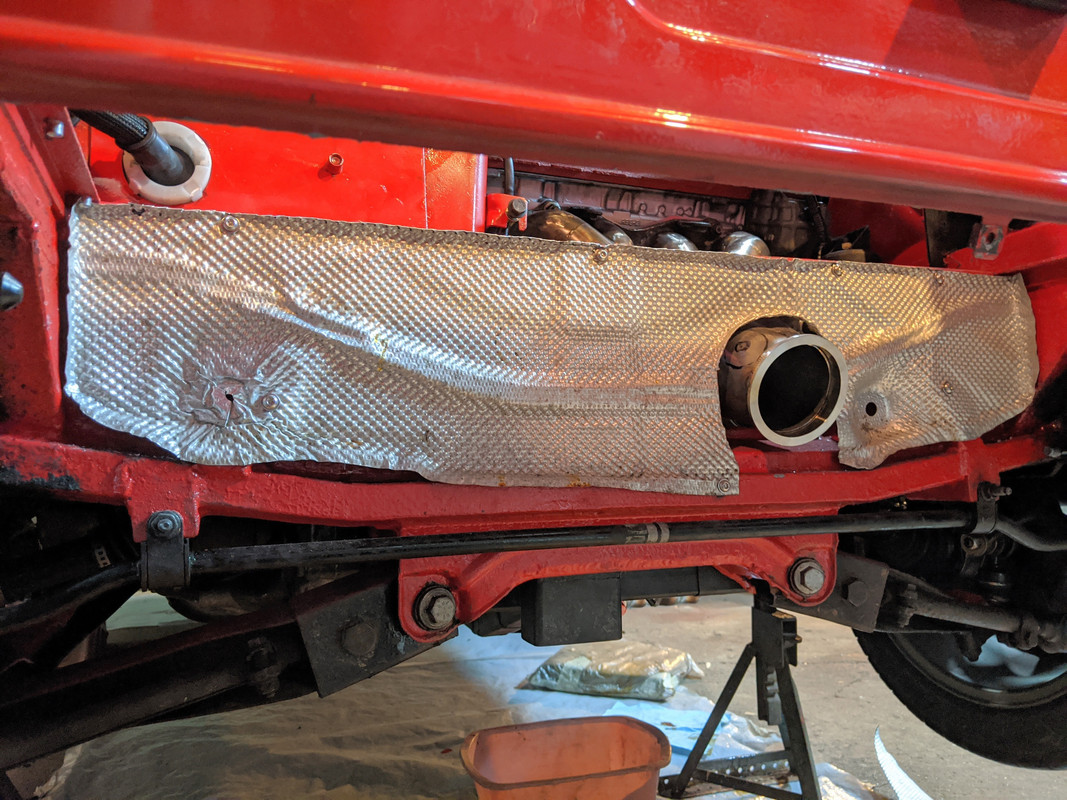
I cut up the Acura swaybar end links and used them to make the upper support brackets for the heat shield

IMG-20191215-125557.jpg


IMG-20191215-125625.jpg


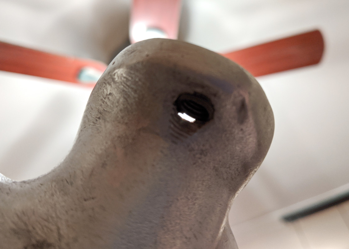
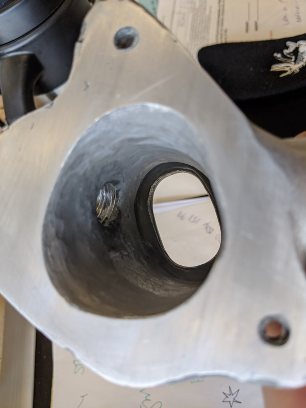
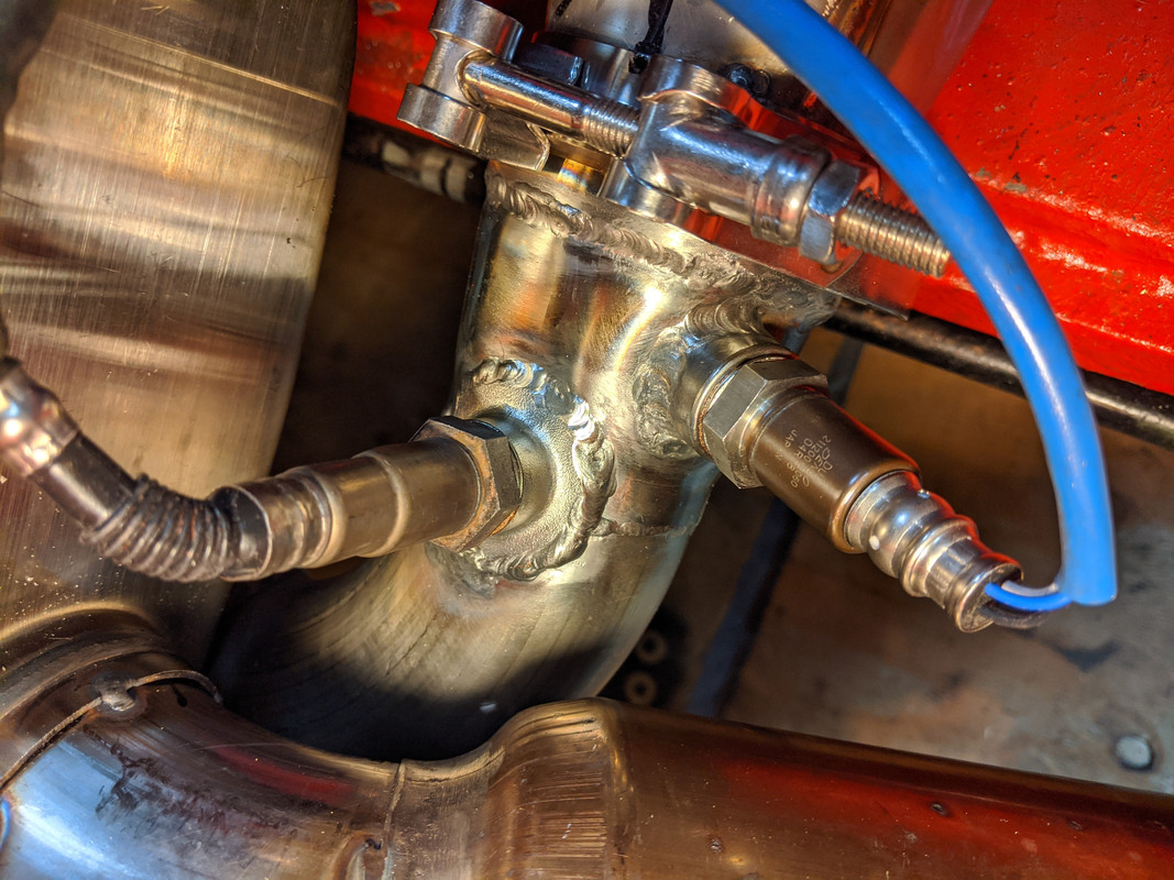
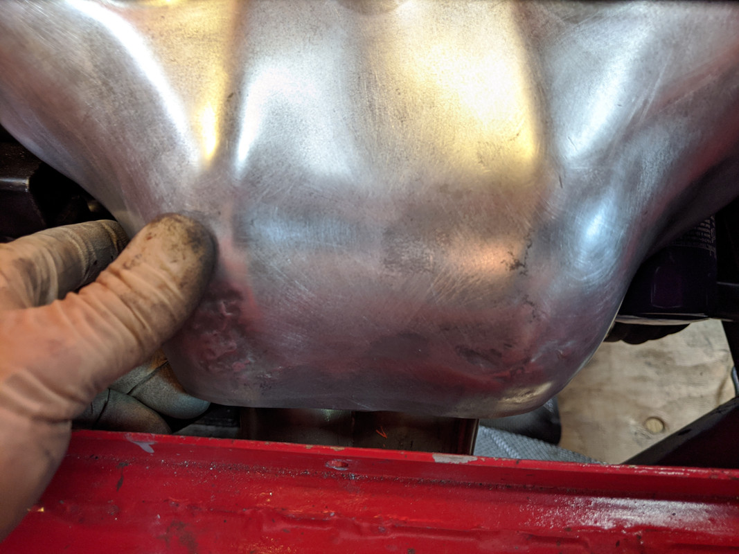
drilled a new hole at the base, and transferred the isolating collar from the old lower section. Had to drill one side off & then silver solder it back in place

IMG-20191215-132117.jpg


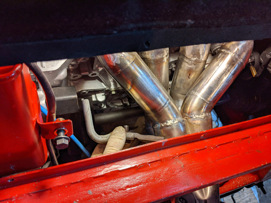
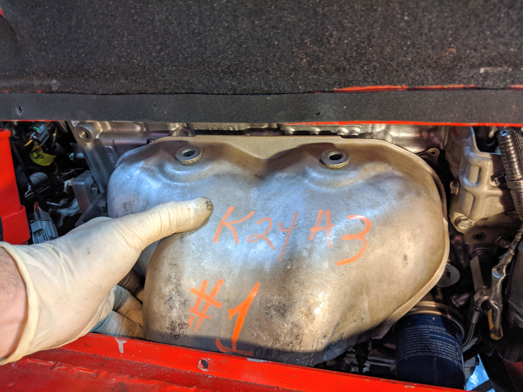
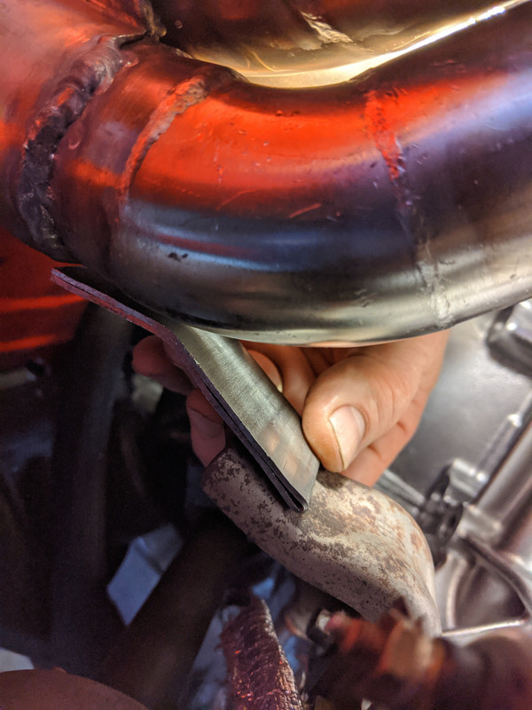
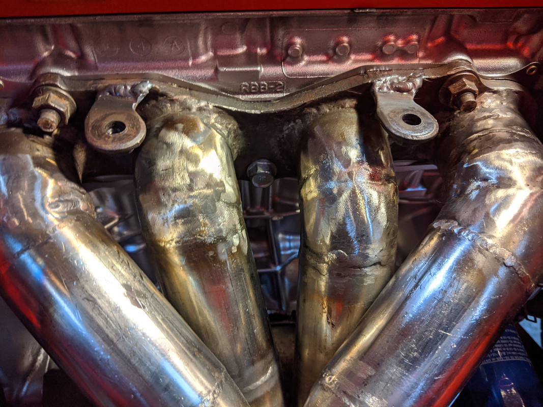
Have to make & weld a tab to the collector for that.

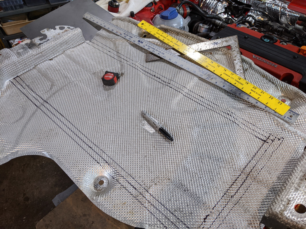
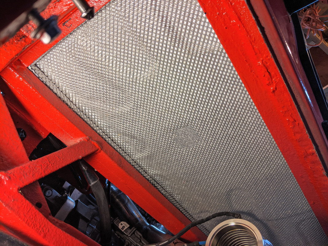
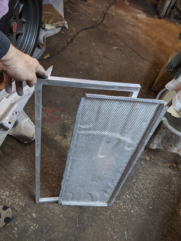
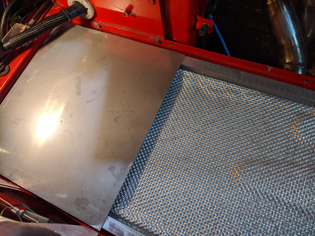
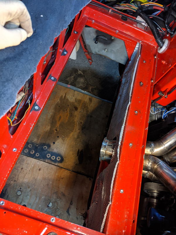
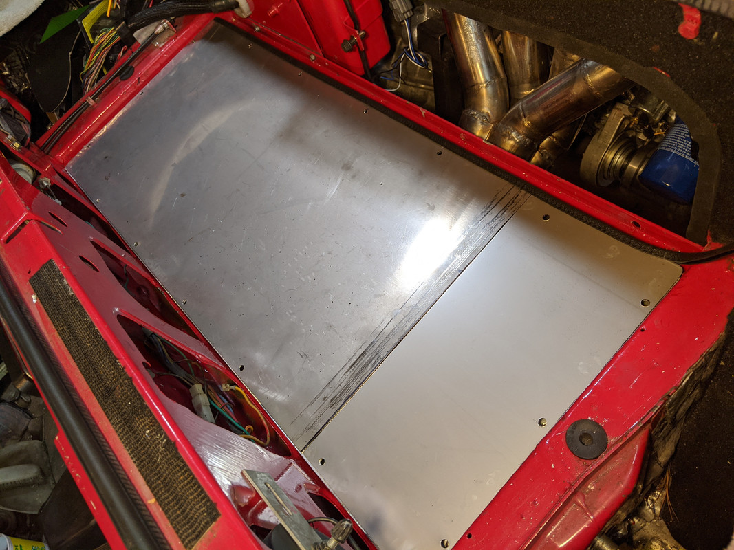
Lastly, I started laying out the heat shield divider for crossmemember area. Probably going to drill & install a series of SS M4 rivnuts & use SS M4 hardware to secure it.

IMG-20191215-141154.jpg
 
Last edited:
Great work and progress. Especially that whole no dripping thing. :)

Keep in mind that an air gap is one of the most important insulators you can have as well as ensuring minimal direct contact between the radiant shields and the body to minimize conduction. Additionally it would be best if you can find some way to not have any body structure visible to absorb radiant energy. (My 87 X’s rear structure’ gets surprisingly hot from the exhaust which I think is from running lean and or a clogged cat.)

A side note, your brace (which is an excellent add) could add a notable amount of heat to the bracket, the base of which you have wrapped some wiring directly to. You have done a great job of protecting it from radiant energy but with it in direct contact with the mount you may end up with conducted heat damaging the wires. A bit of air gap might be in order here.

C0BD44F5-4694-4F7A-9476-2A9CF46E03CD.jpeg


Is the bit of stainless you are welding to the header of similar gauge as the brace bracket? It also looks like it might benefit from a bit more length at least to bare on the lower bracket more. Any worries about the welded tab being such a cantilever, would it be better to connect it in two spots to the header and have a captive nut to run the fastener from the block mounted bracket into?

Sorry this comes off as negative, this is very good work.
 
Thank you, Karl.

I always appreciate constructive criticism :).

I will re-route the oil temp gauge wire - I can run it on the right of the new bracket, just has to be clamped to keep it off the axle.

With the header support, the piece I'm welding to the header is a flattened section of SS tubing, approx 1/8". Not sure increasing the thickness of it is required - I wanted it to be in-between the header thickness and that of the elbow. I could add another layer to bring it to 3/16". It does have a captive nut for the elbow bracket. I can't increase the length over the elbow due to the dogleg in the top surface, if that was what you meant. I'm going to add a section at the collector end, so the load isn't just at the seam - something like one of the drawings on the left, either perpendicular or parallel to the existing:

IMG_20191216_071251.jpg
 
Last edited:
Installed 7 M4 rivnuts for the vertical heat shield. Used M4x16 SS Torx button head.

IMG-20191216-165342.jpg


Started securing the trunk floor & heat shield. Did more M5 rivnuts than I had planned for some reason - set them approx 5" intervals. I marked & drilled the floor panel and the aluminum frame first, then used that to mark the locations on the floor rails. I set it so the floor panel is offset over the frame for a finger gap along the front edge to allow one to lift the panel out, hence the edging along that side. Of course some of the rivnuts walked (couldn't hold the drill perpendicular on the back lip, even with the small body Makita), so I have to enlarge the holes in the aluminum channel to allow some flexibility of placement. I had only drilled them to 1/4", so not really a big deal to go to 5/16" or 3/8" on some of them. Also have to order more M5x30 screws - the ones I had on hand are allen vs. Torx - total pita to work with for something like this.

IMG-20191216-165231.jpg
 
Last edited:
I was thinking more along the lines of this
View attachment 27954

For those wondering, yes this is the type of sketch I give the model shop to make parts for me...

I understand. however, I want the main weld support to be carried by the collector - if I run the bracket up at the front it will be welded to one runner only - where I have it it's bridging the base of two. I don't think it needs to be as rigid as your design would make it. Basically, I just want to remove the whiplash effect others have mentioned, but allow for however much flex/expansion/contraction will take place with the runners.
 
Finished the heat shield / floor pan mounting. Had to enlarge two rivnuts to M6, due to drill bit walking.

IMG-20191217-161928.jpg


Cut & drilled the short panel required to make up for the fact I chopped a piece off the floor pan thinking it was a surplus section. Not sure if I will weld the two together. I have my doubts regarding my competence in getting a clean weld with no distortion.

IMG-20191217-165921.jpg


Applied the closed-cell foam to the underside of the frame. I used the hole punch to make sure the screws don't twist the seal when bolting it down.

IMG-20191217-182803.jpg


Welded an extension to the header support brace. I'll weld it to the header once I've finished the collector welds.

IMG-20191217-172937.jpg
 
Ordered a set of the Rota Kensei wheels, M12x1.25 wobble nuts, 67.1 - 58.1 hubcentric rings & new 225/45 & 205/50 x15 BFG's from the TireRack. My current tires are almost bald, and likely will be after I do some burnouts with the new drivetrain :D I like the deeper dish on them - they look great on Stingray250's X.

index.php


I'm already so far into this, what's another $1,400? Besides, it's nice to have more than one set :D
 
Last edited:
Finished welding the headers, so that is installed & torqued to spec.

IMG-20191219-160733.jpg


IMG-20191219-160741.jpg


plugging away at seam welding all the flanges - only got three done this evening. another 5 to go , I think.

IMG-20191219-173758.jpg


O2 sensors installed.

IMG-20191219-175535.jpg
 
About 1.75" height reduction, MWB says "reduce about 2 inches" in the notes.
IMG-20191119-173512.jpg


IMG-20191119-173517.jpg

So, one issue that arises with chopping down the lever is that pedal return response is affected - at least with the K-Tuned TB, it feels 'soft". The ability of the TB spring to act on the pedal is diminished with the loss of leverage. I have to see if I can tension the bobbin spring further, however I feel that it is likely I will need to add a spring at the pedal to stiffen up the pedal feel/return action.

Problem is of course, adding a coil spring that would sleeve the collar & act on either the inner lever or the pedal arm is not possible without modification to the arm.

EDIT: I'm going to plan on adding a perpendicular pin that bolts to the two rear pedal bracket holes, with a spring that will hook around the pedal arm, something like this:

The pedal spring from a Volvo 240 (# 1205927) has the appropriate form-factor.

IMG_20191220_112341.jpg
 
Last edited:
Back
Top