lookforjoe
True Classic

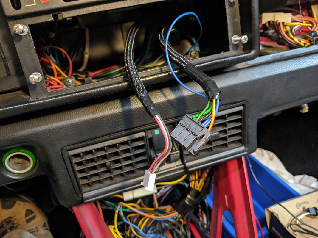
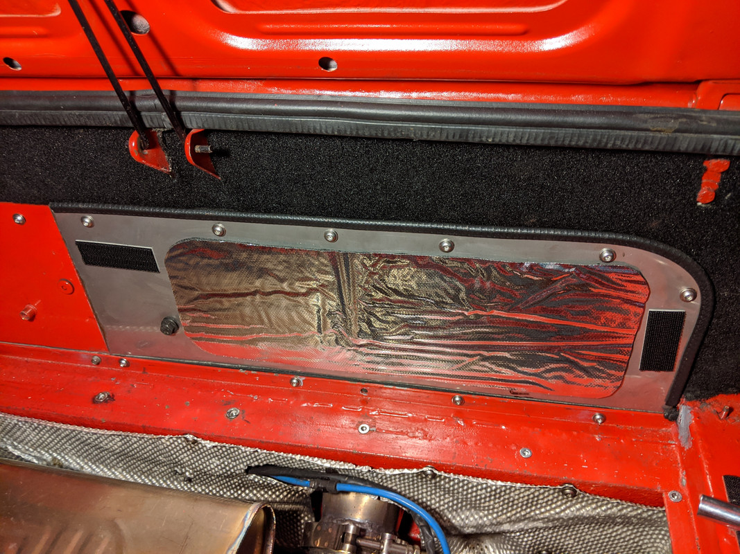
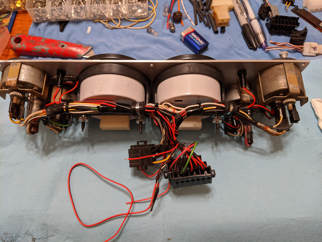
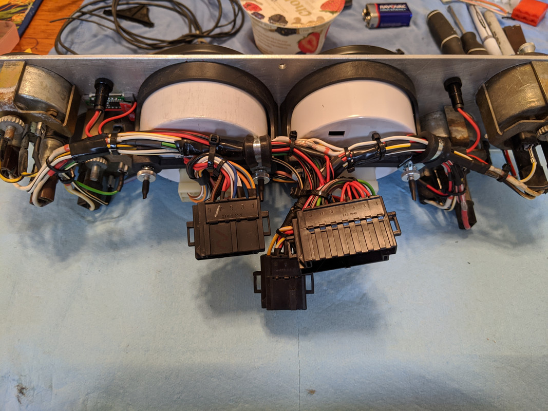
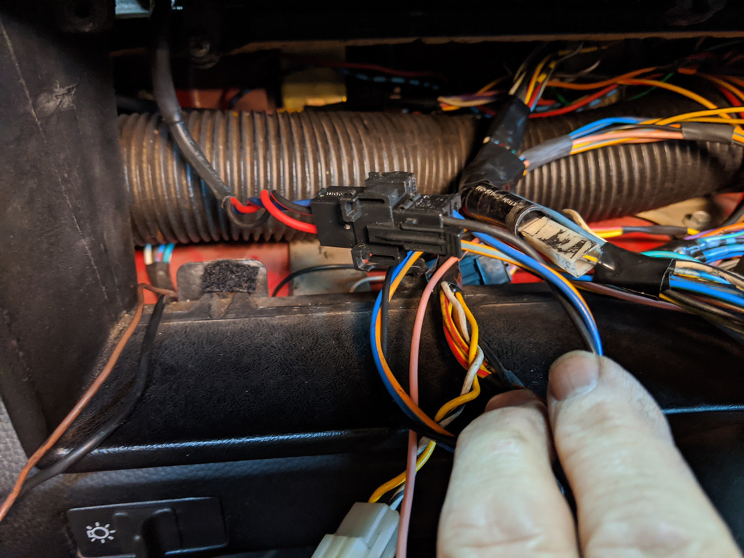
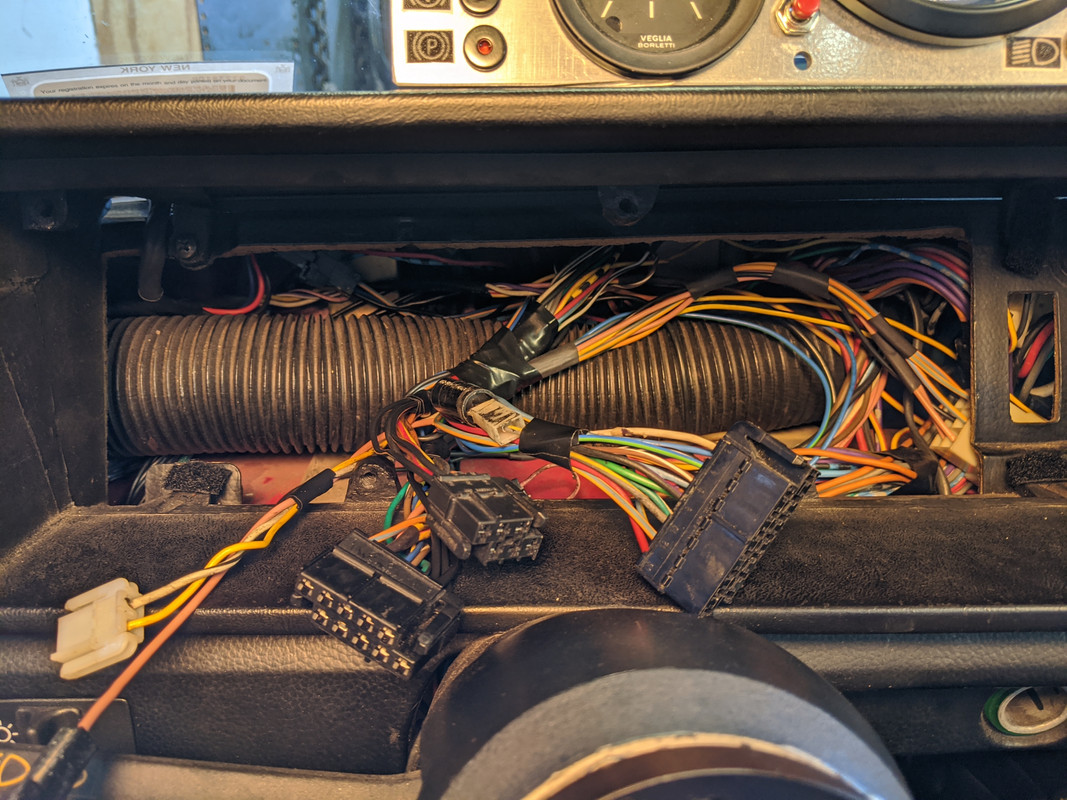
Body side - power, ground, dimmer circuit for illumination, sender signals

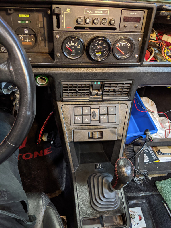
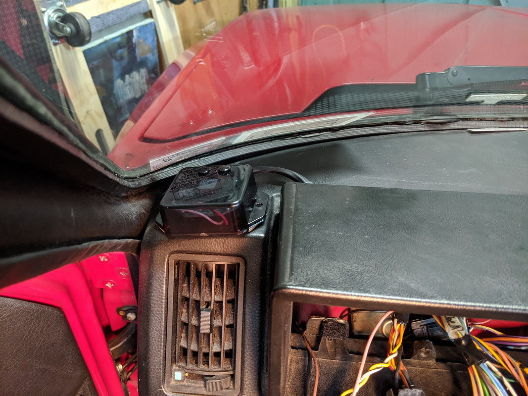
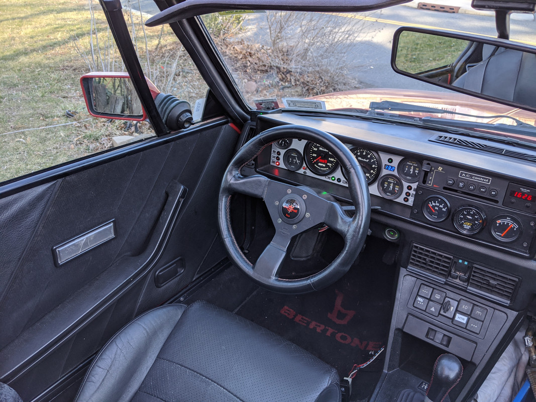
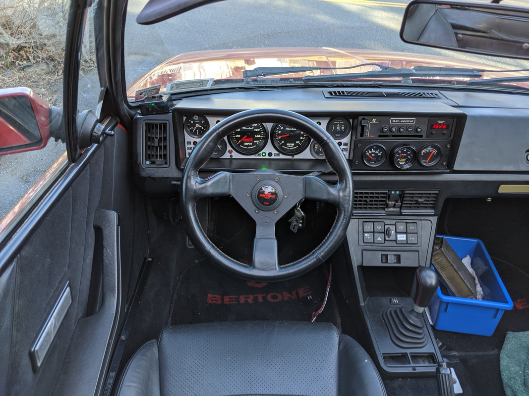
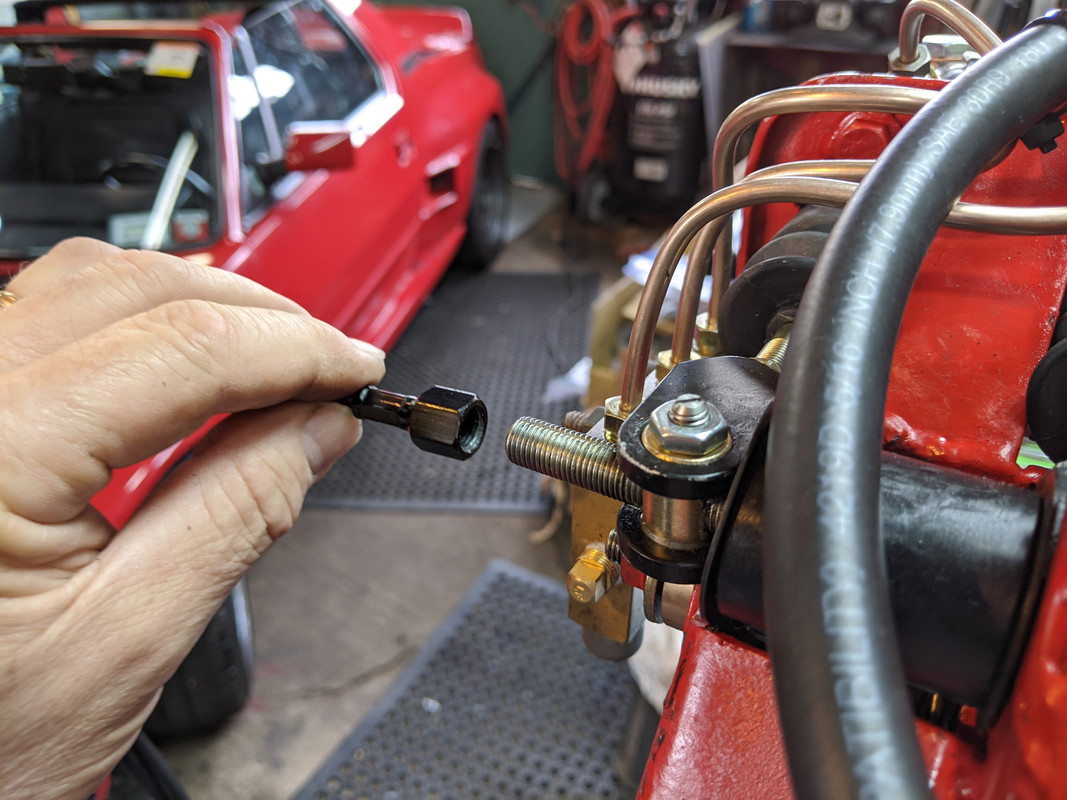
Installed. Need to get black machine screws, the stainless isn't going to work for me
Last edited:

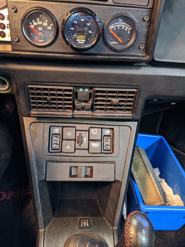
Argh... disappointing. I really would like to figure out a way to make the stock mid-80's dash stuff work with the K20 bits.


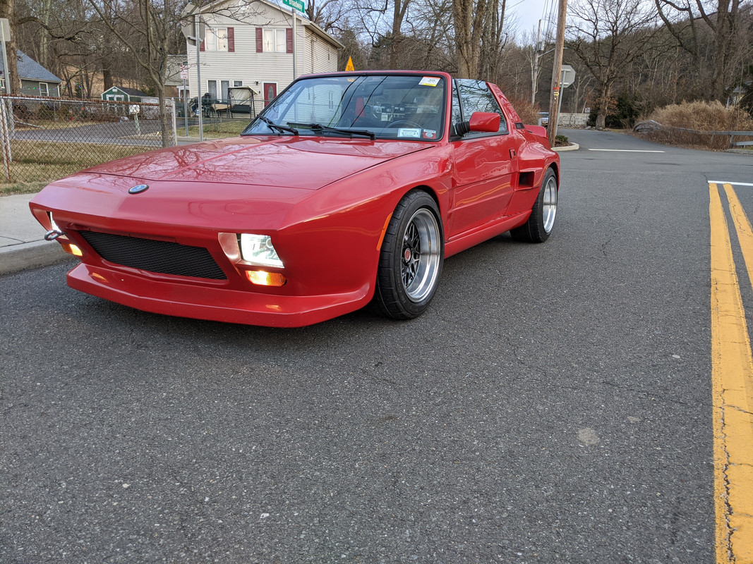
Thatsa nice!
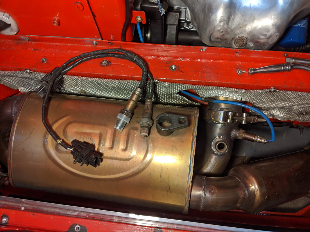
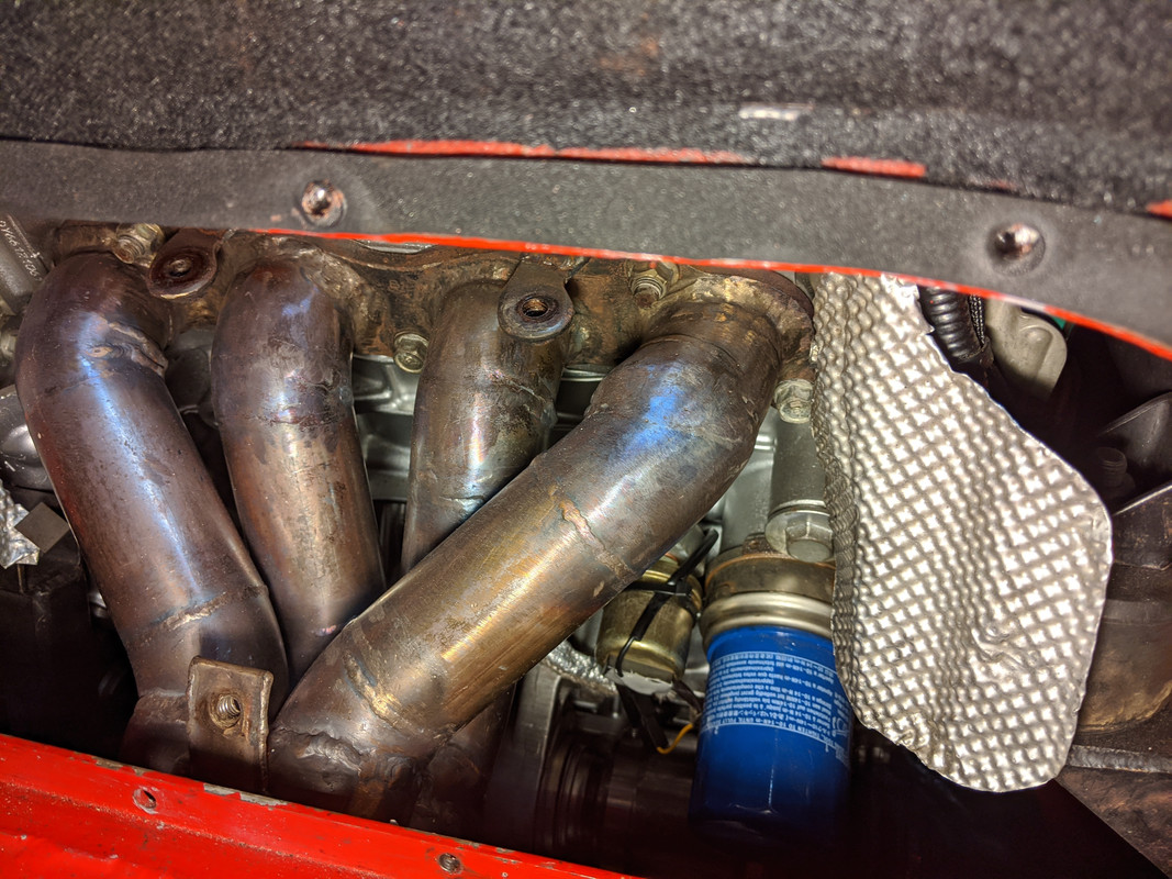
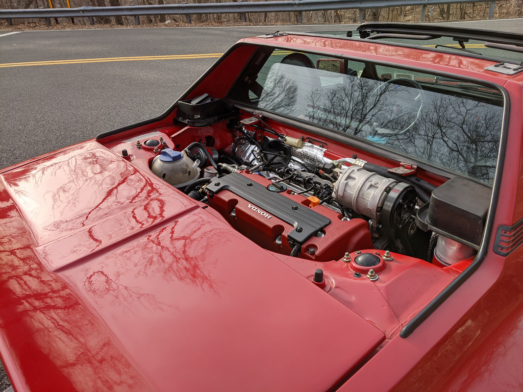
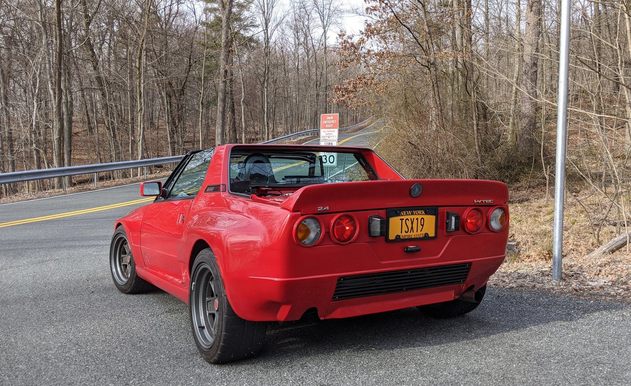
How was the drive since you clearly needed to get it all heated up. The exhaust stainless certainly looks like it has been heat cycled")
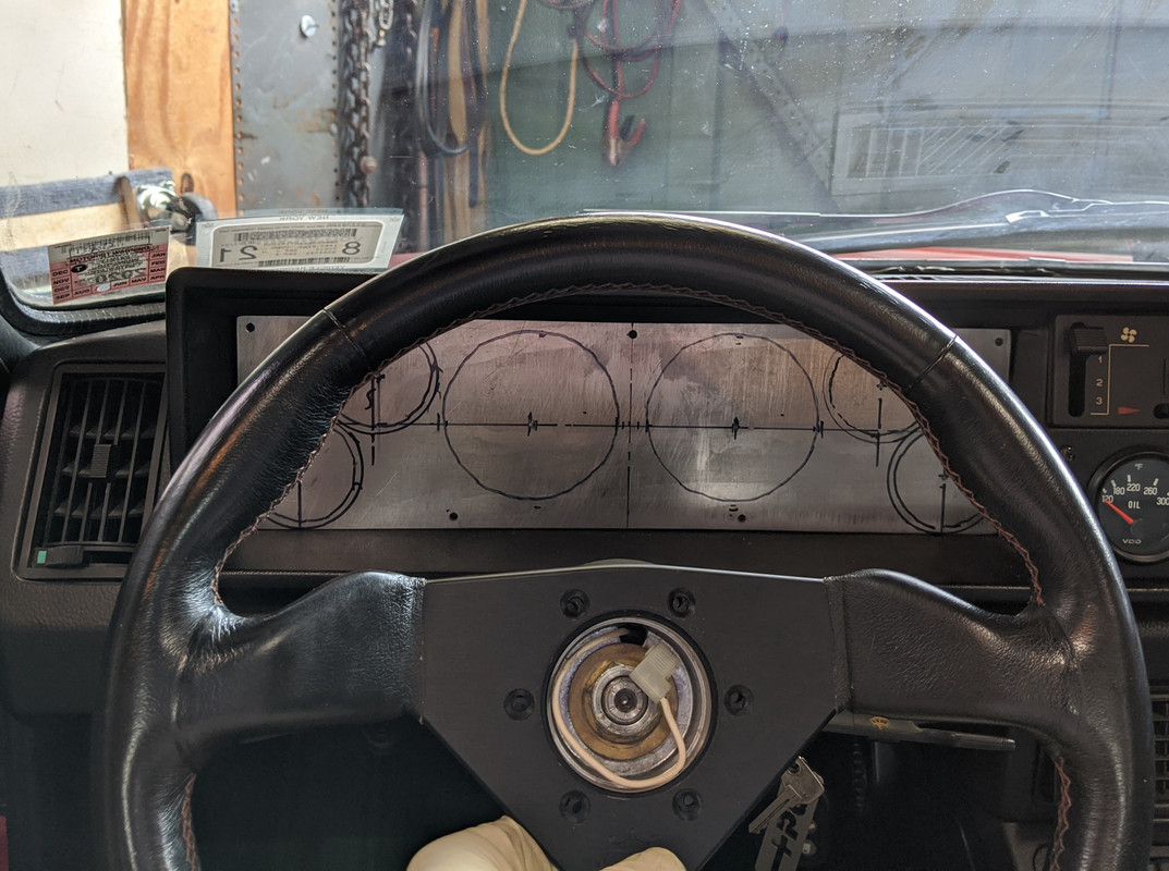


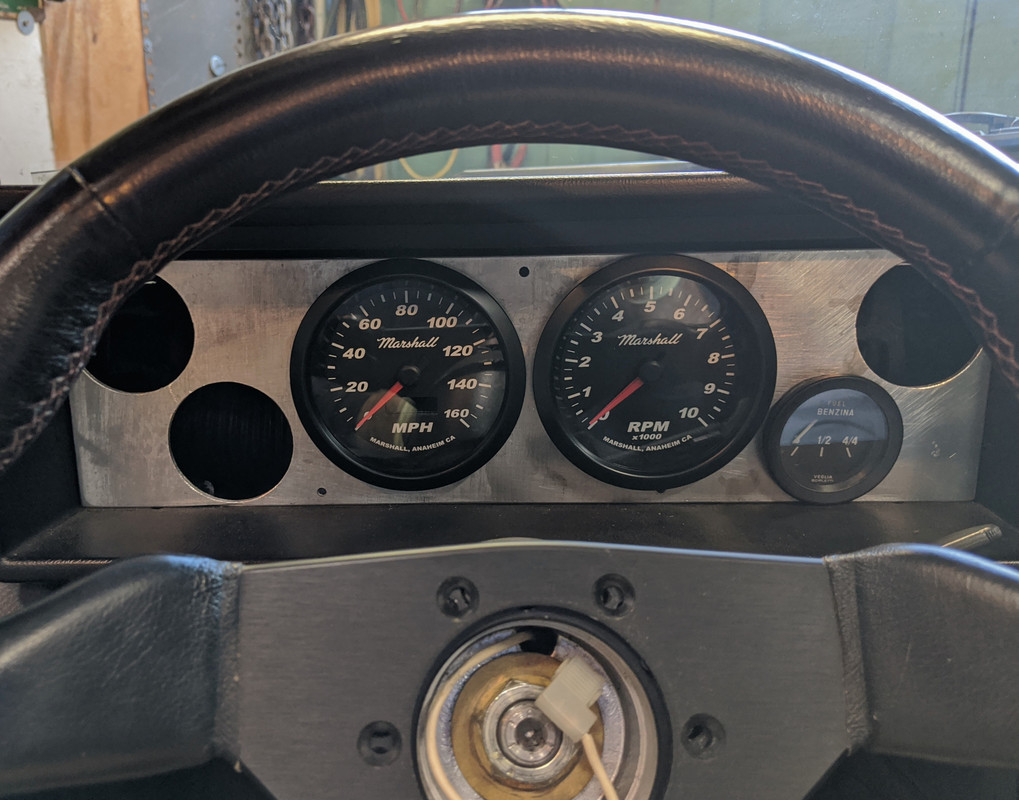
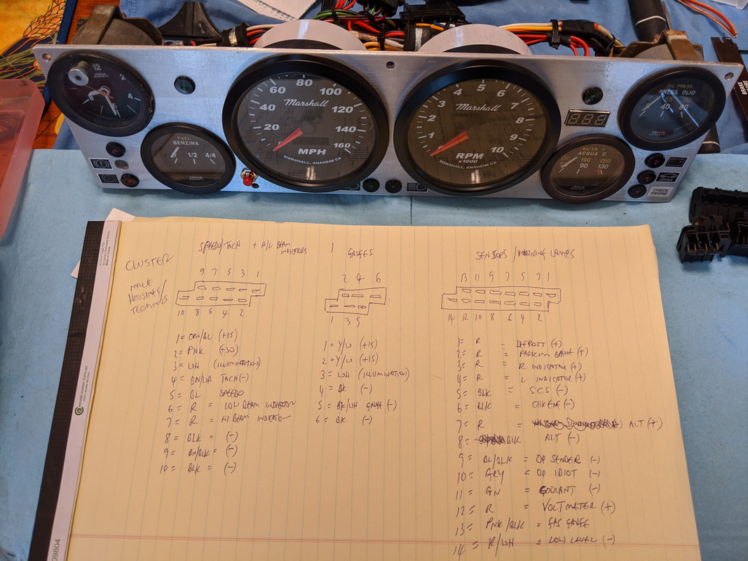
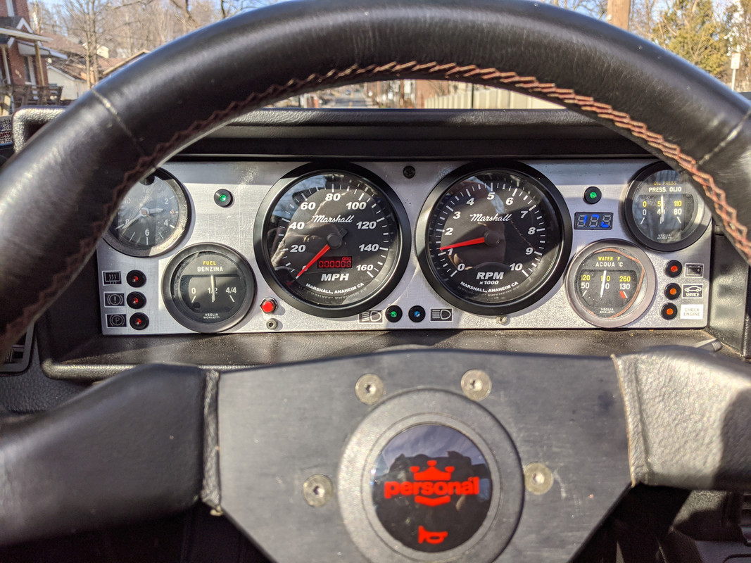
You could rotate the upper small gauges to get the sweep in view leaving the dumb part of the gauge obstructed.
On an aluminum panel I made I found some stick on carbon fiber look vinyl. worked in my application but might not be the look you're after.
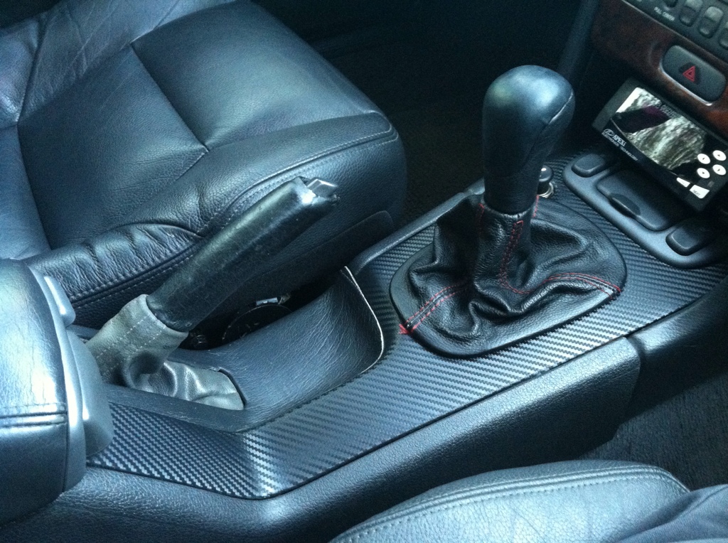
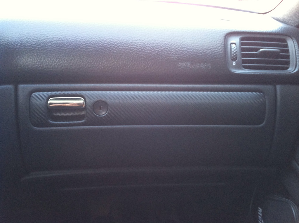


Thanks for the suggestion. I have a large roll of the CF-vinyl, I had used it on my Volvo years ago
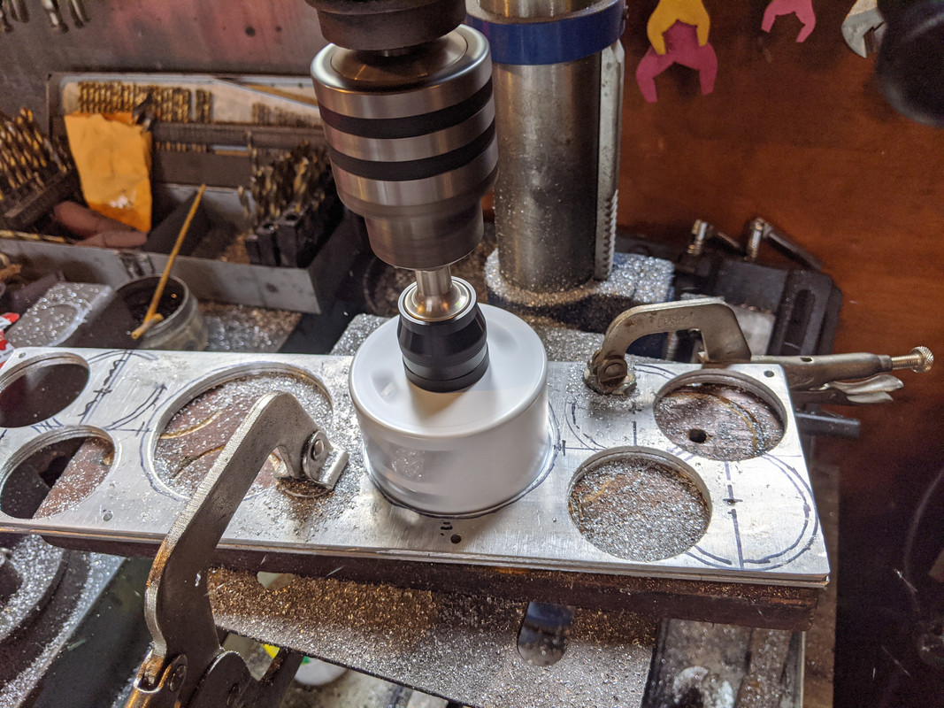
I decided to leave it aluminum, so I just clear-coated it
Hard to photograph from the actual viewing angle - it's actually better than this


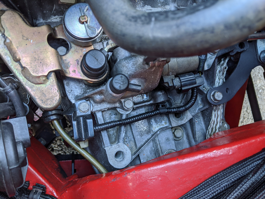
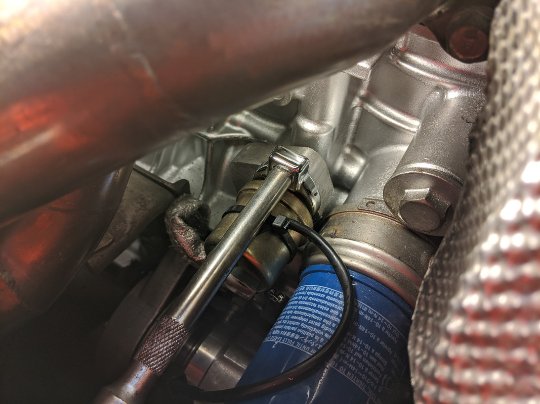
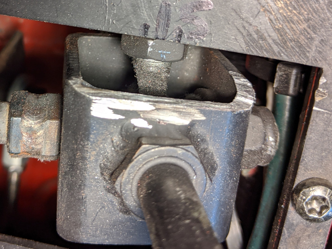
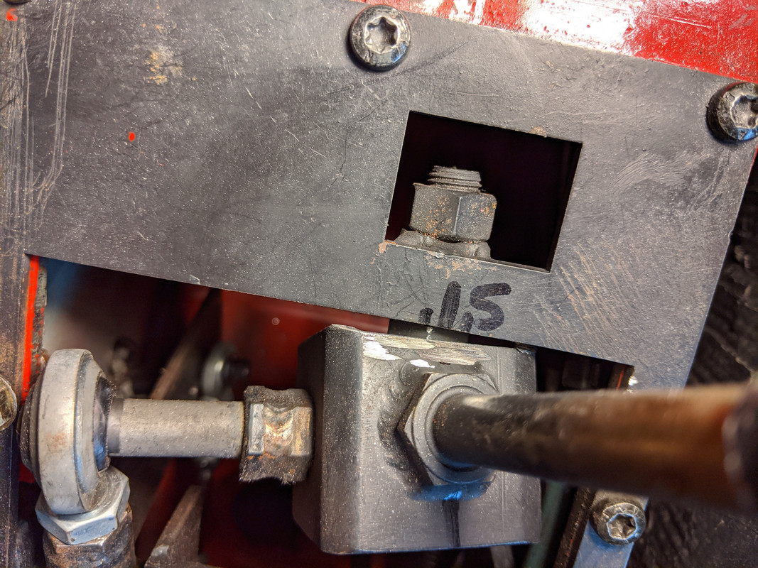
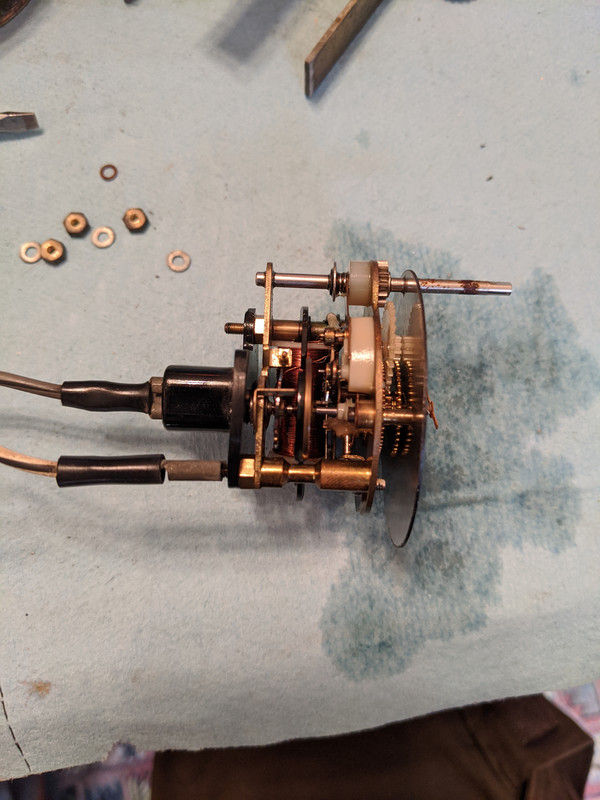
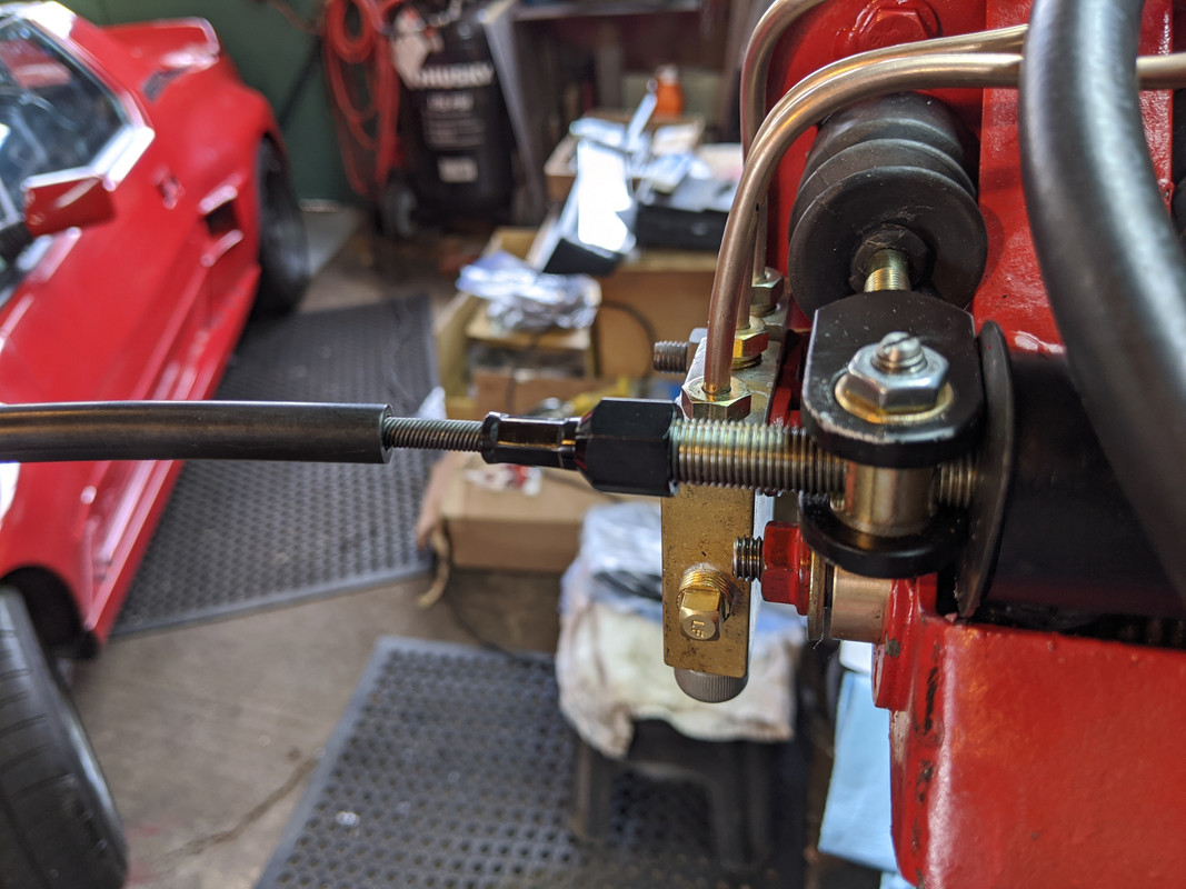
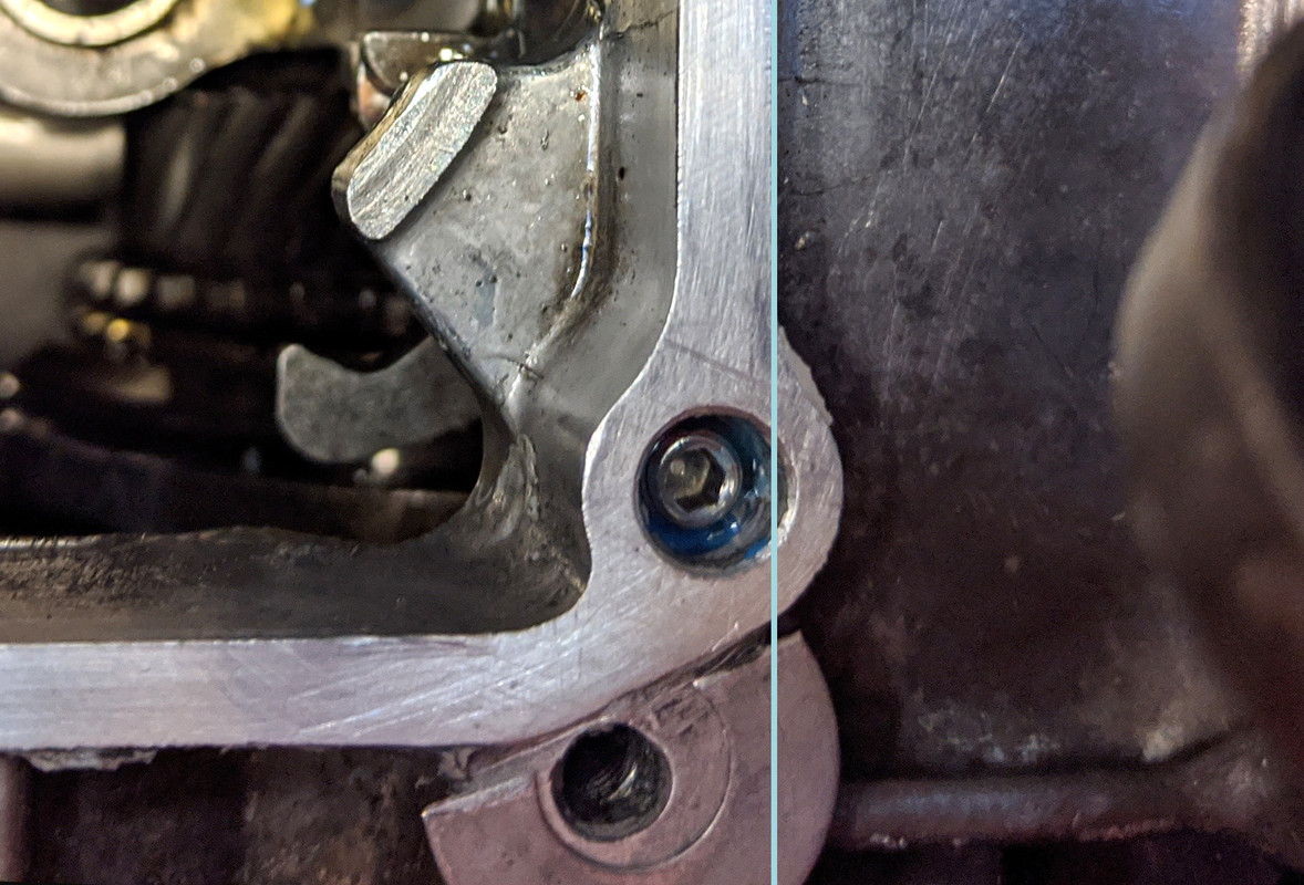
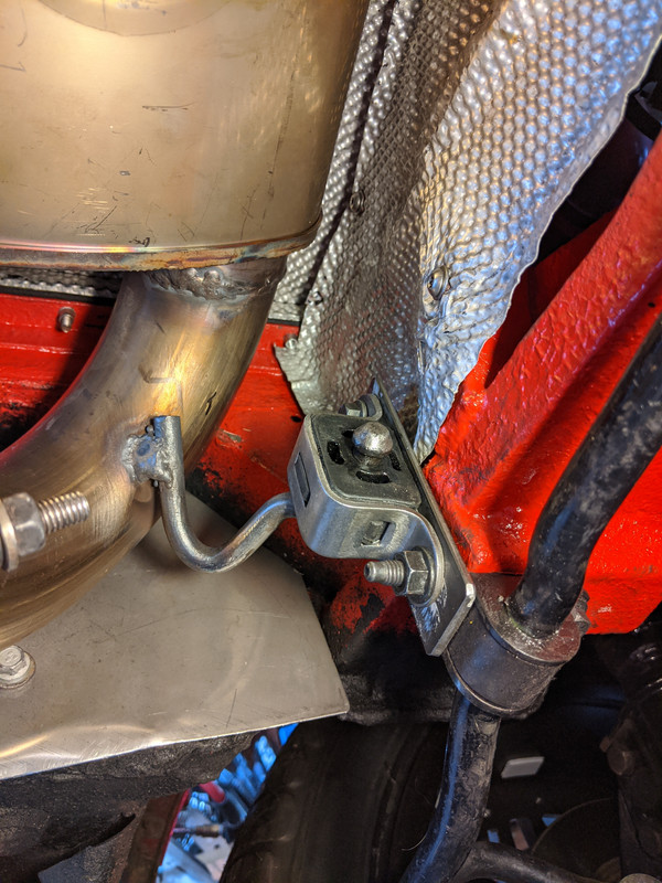
Is it the gate assembly or are you blowing oil out of the breather area right there? It looks like there is oil on top of the assembly and then on the housing casting underneath and behind it.
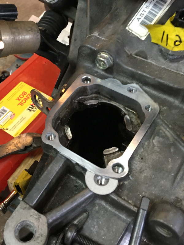


 So, I need to get a new one....
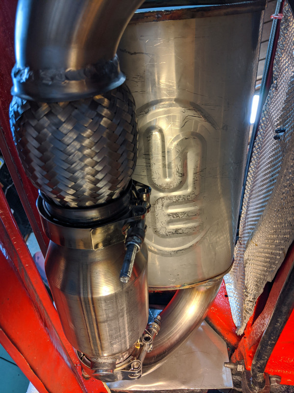

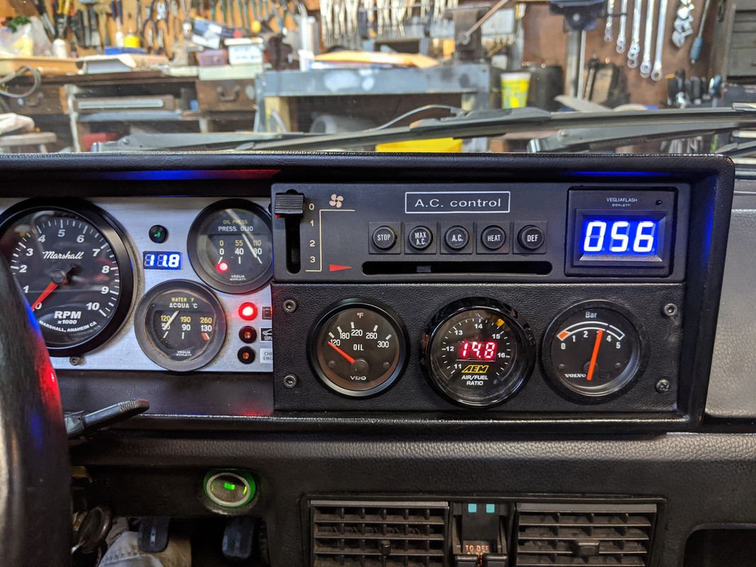 (EDIT - AFR discrepancy ended up being due to exhaust leak between sensors )