kmead
Old enough to know better
- a little too easy to get up around 100, so I will have to be very careful once I am driving it routinely.
Hmmm, such a surprise")
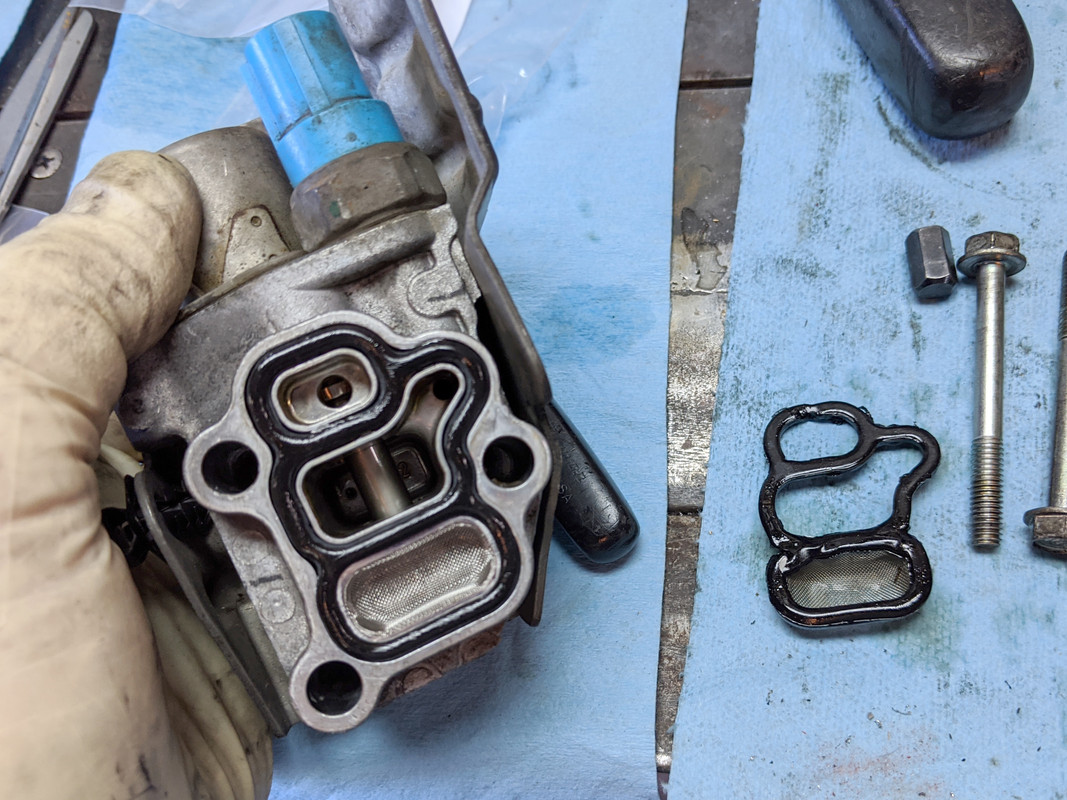
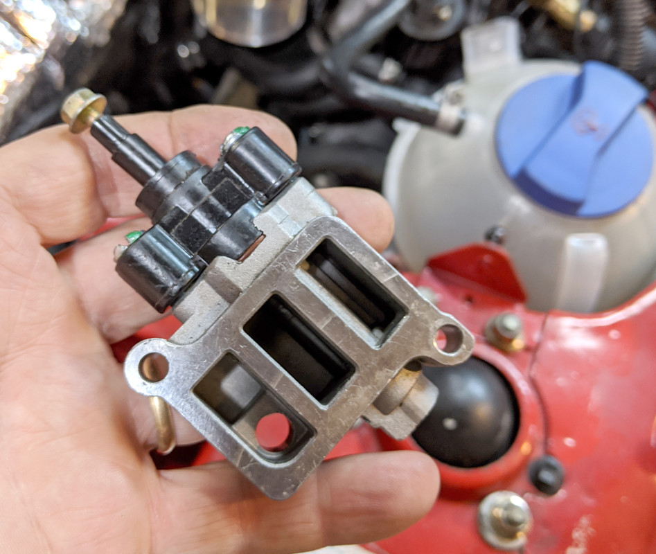
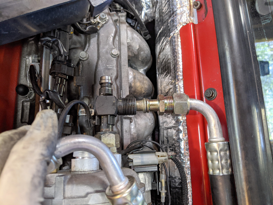
Getting to a proper idle is important as a stalling engine is a real safety issue. Bummer it also affects the lower to mid throttle response. I have the lower hp version of this engine in my Honda Element and really do like its behavior overall, I believe the version I have is designed to enhance the torque versus high hp which makes it pretty driveable despite being in a heavy box. My other Element (we have two now) had an issue with the cam advance system going into limp mode which was frustrating to solve (they really like clean oil and the right oil level which the past owner apparently failed to understand) and a huge drivability issue.
Sorry the teething is proving so frustrating.
Hmmm, such a surprise
Getting to a proper idle is important as a stalling engine is a real safety issue. Bummer it also affects the lower to mid throttle response. I have the lower hp version of this engine in my Honda Element and really do like its behavior overall, I believe the version I have is designed to enhance the torque versus high hp which makes it pretty driveable despite being in a heavy box. My other Element (we have two now) had an issue with the cam advance system going into limp mode which was frustrating to solve (they really like clean oil and the right oil level which the past owner apparently failed to understand) and a huge drivability issue.
Sorry the teething is proving so frustrating.
Last edited: