Performing Honda K24a3/AST5 6spd Conversion

As usual lots accomplished.

A few days ago I had raised some questions about the reinforcement of what I meant to be the front lower a arm suspension pickup points which are now also engine subframe mounts.

I wasn’t clear and didn’t follow up on your response.

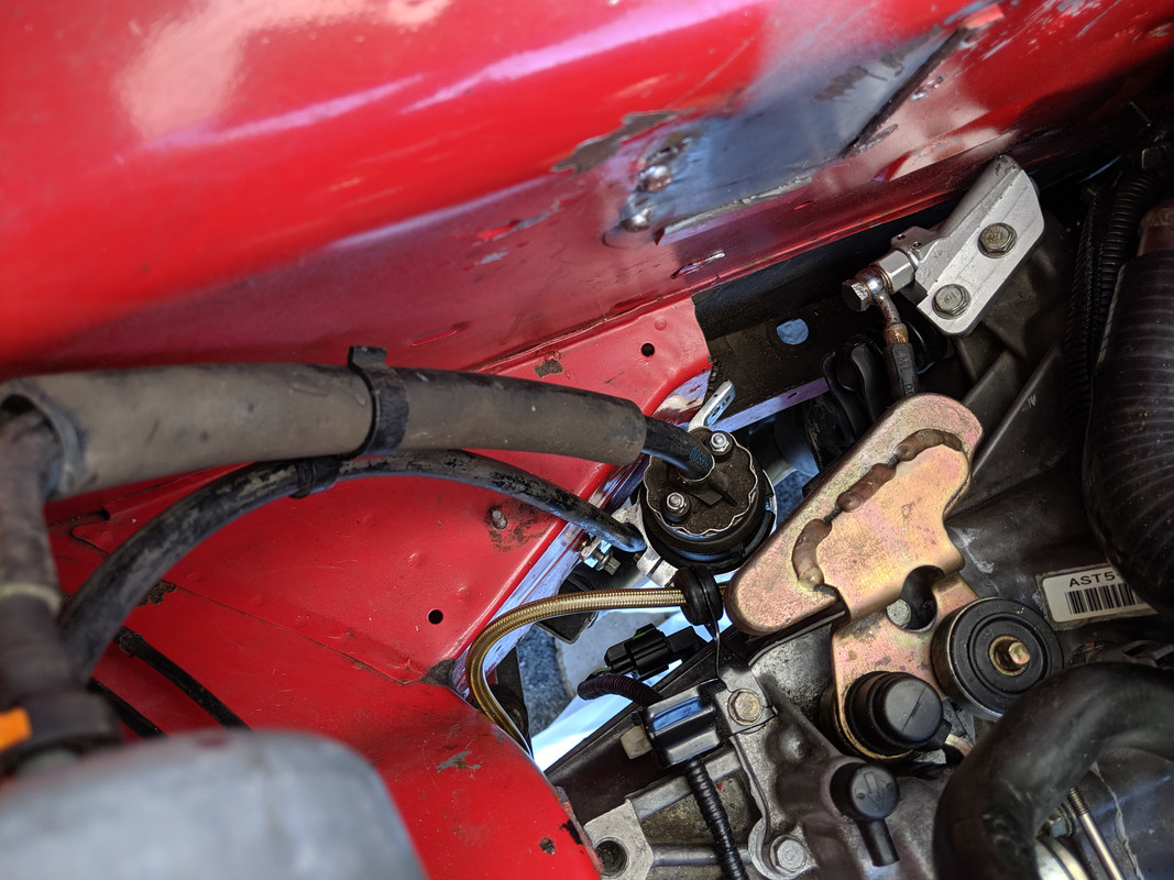
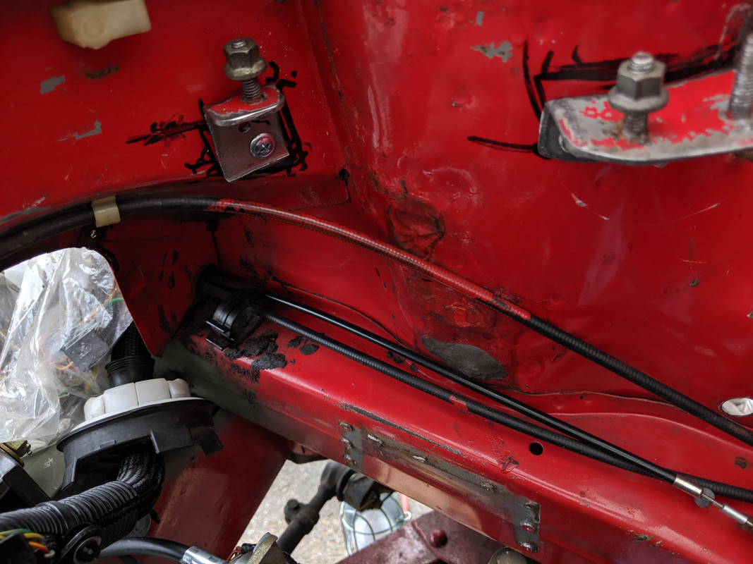
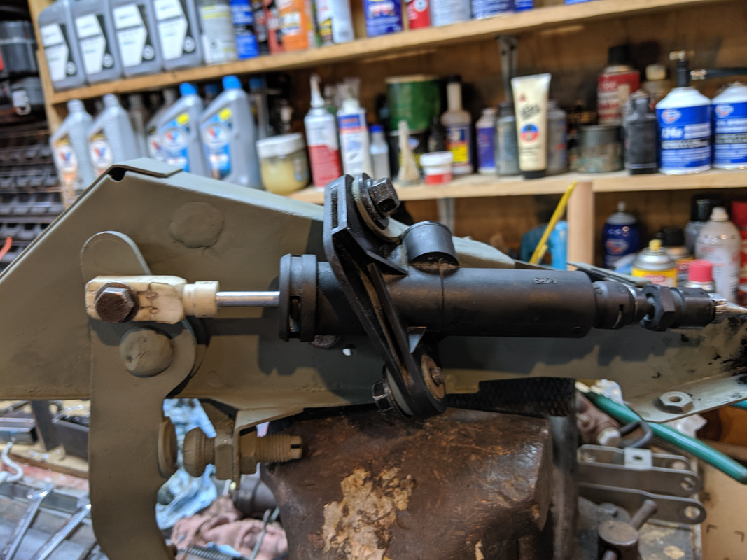
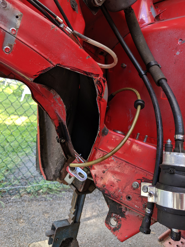
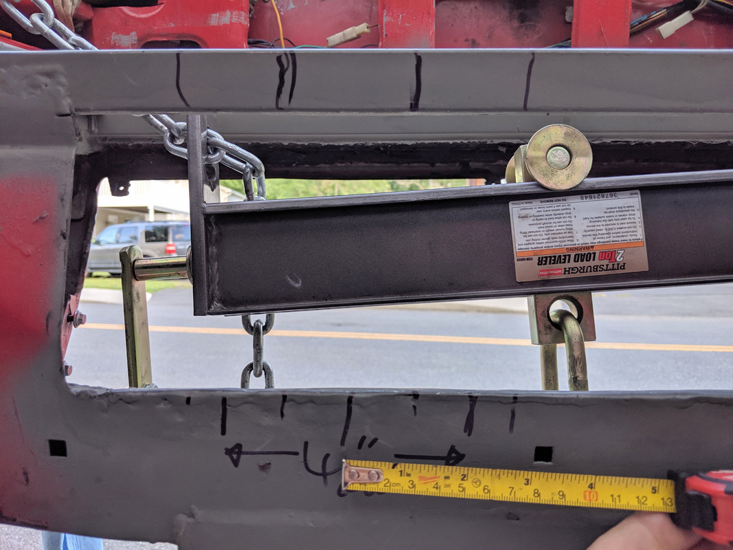
What I meant is that since the top area of the front mounts is open now, it would be a good time to add additional bracing inside the area before you close it up and then ensure the top surface you put there has some holes to be able to plug weld the outside surface to the underlying structural reinforcements.

The area sort of called out in green and yellow, the object floating to the side would be some form of reinforcements installed upside down to the way I have it shown, welded to the lower surfaces and then the upper surface you will be adding welded to the this reinforcement to maximize the box section across this area.
5842AD86-37DE-4AEB-9C03-D80F6889FA3C.jpeg


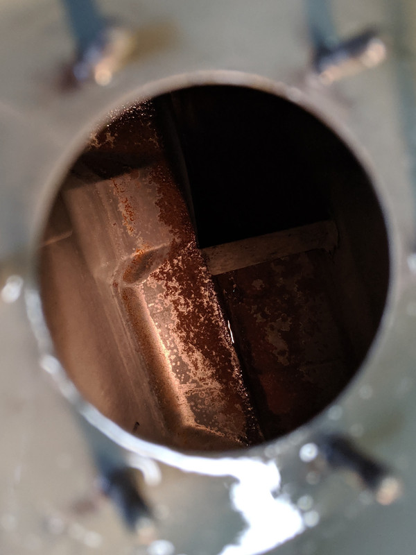
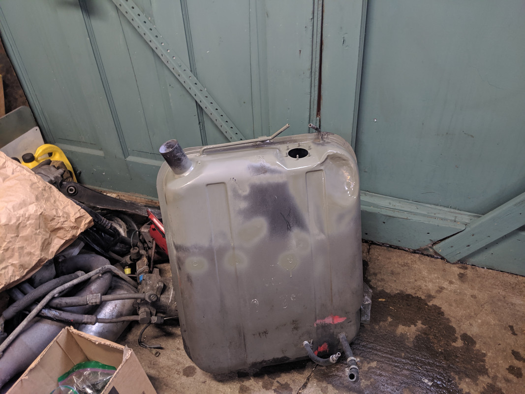
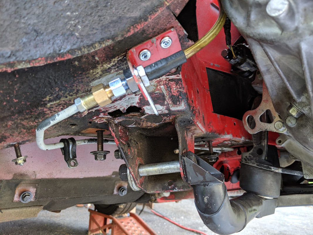
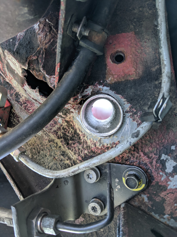
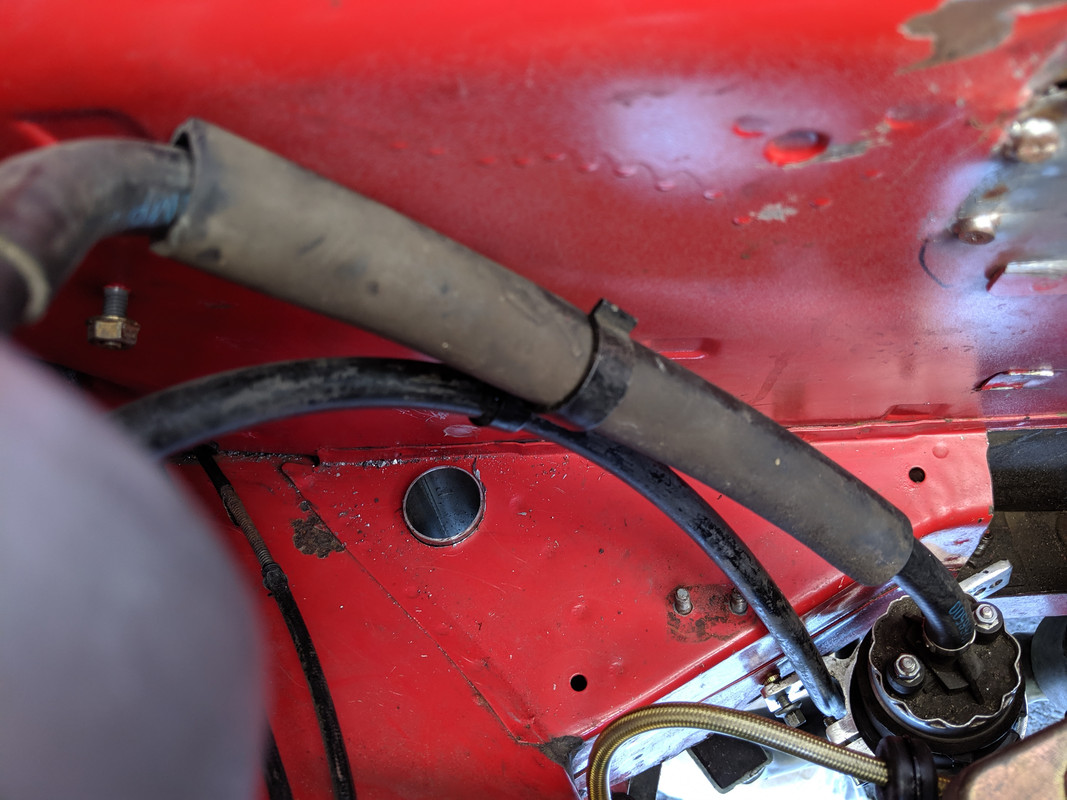
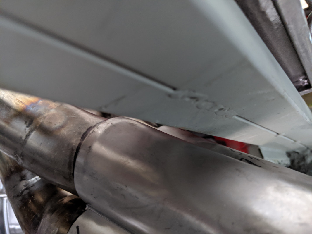
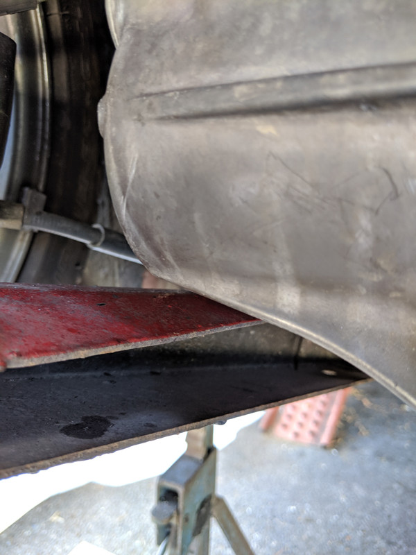
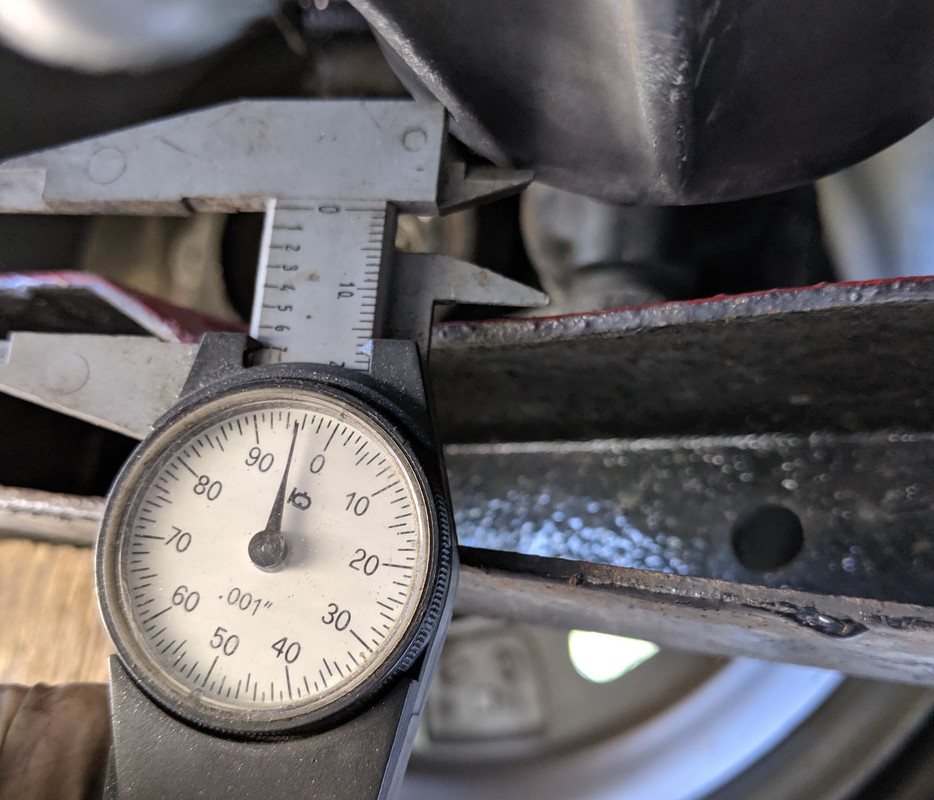
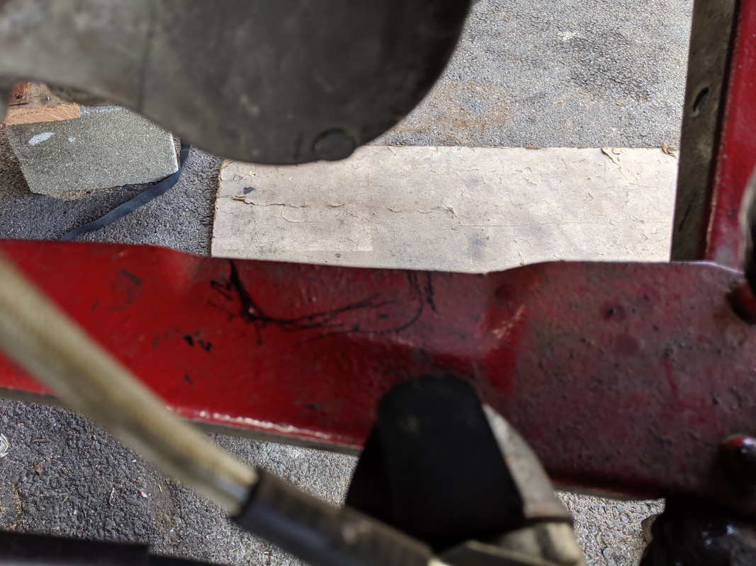
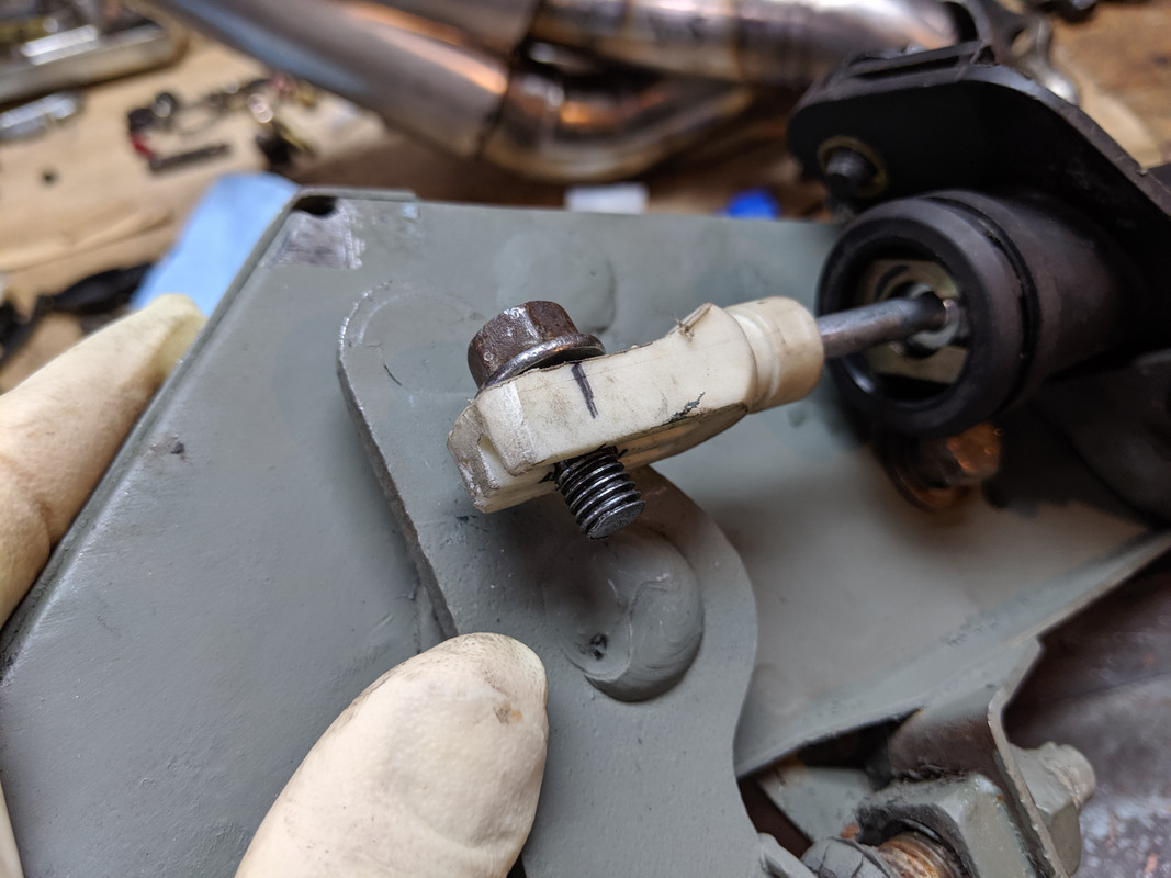
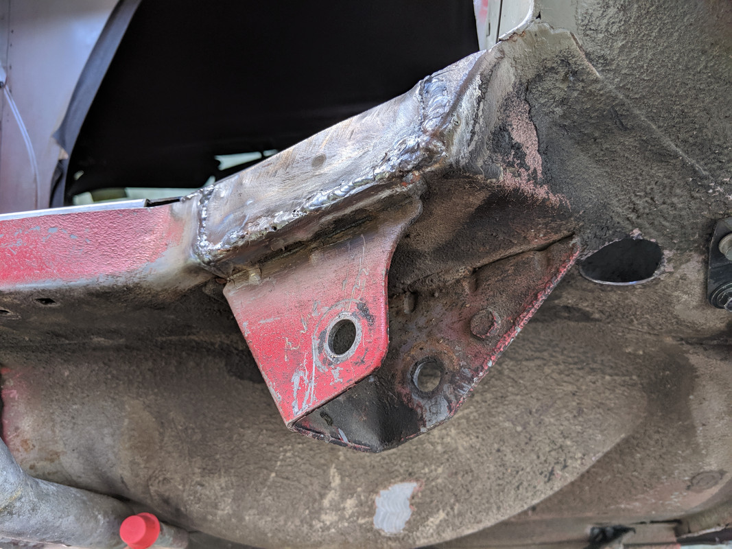
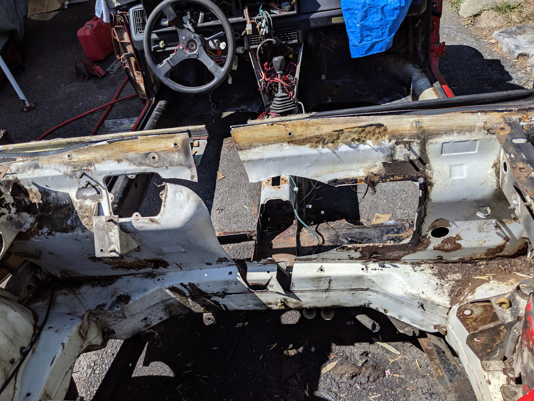
So this seems even more important if what is shown in this picture is rust through of the lower surface next to the the actual a arm mount underneath
CB8E0836-8813-44FB-9E4A-7F5CD5E7E18B.jpeg


I think I would want to remove all the undercoating in that area to see what is really going on locally around there.

Just a suggestion.
 
Can you rotate your throttle body 90 degrees? I think that's what MWB recommends and same as Rodger did (see his pic that you replied to here: https://xwebforums.com/forum/index....-good-start-volume-2.32624/page-5#post-305106)

I suspect he will start having issues with other things clanging into other things. The stack of items on top of the TB will end up in the midst of the cooling and what have you to the right.

In Roger’s image the TB is moved to the left 10 inches to get away from all of that stuff.
 
Welding a gas tank. I have done several over the years. Remove the fuel sender cover and let the tank breath. I have used a vacuum cleaner on blow to vent the tank outside of the garage. If the tank is dry and vented for a day, you can weld it without issue. I then plug all the openings using duct tape and put .5PSI pressure on the tank and spray the welded area with Fantastic House Hold cleaner. It will bubble if there is a leak.
Impressive build, lots of head scratching. I thought I was the only one having issues.
Well done.
TonyK.
Grimsby Ontario Canada.

Thanks for the input Tony, I appreciate that. I will follow your directions.

As usual lots accomplished.

A few days ago I had raised some questions about the reinforcement of what I meant to be the front lower a arm suspension pickup points which are now also engine subframe mounts.
I wasn’t clear and didn’t follow up on your response.
I think I would want to remove all the undercoating in that area to see what is really going on locally around there.
Just a suggestion.

Hey Karl

Yes, I will be reinforcing that inner section - I was going to follow Darin's model of adding some vertical webbing within. The section already has a double plate inside. I will consider an insert as you've indicated.

4-A0-E746-E-DB63-4-D2-A-B5-FE-4-BDBC57-DE0-C9.jpg


The left side where the rust hole is will be properly addressed :D 
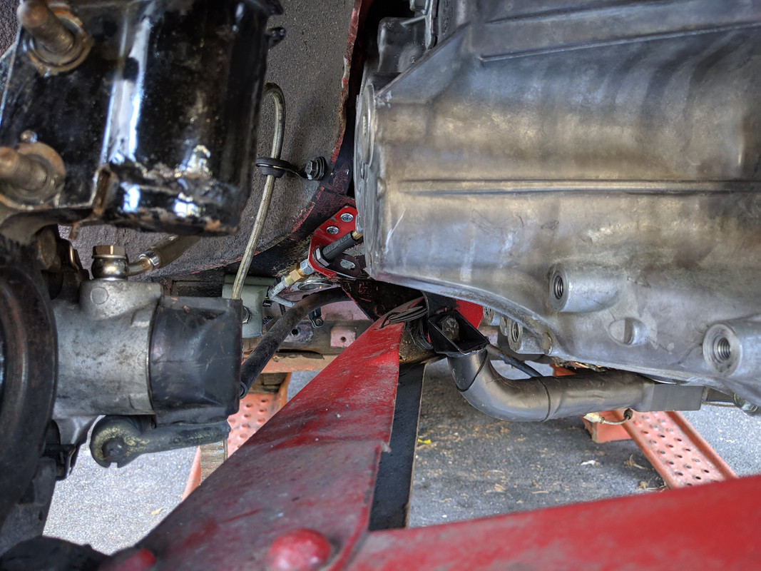
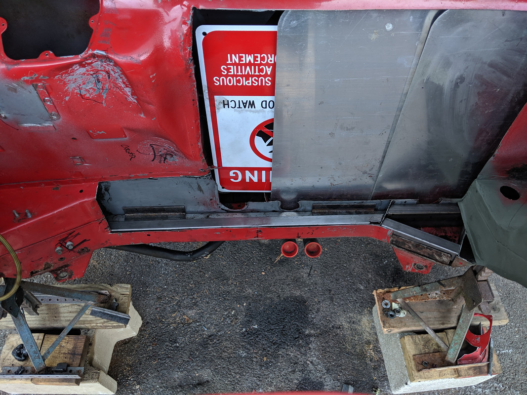
I have a bunch of seam welding to do in that area, so it will be stripped back in preparation & evaluated. Probably have to add a plate that tucks under the pickup where the rust is, then out over a section of the rail underside. That has to all be done from below, no access above.

Can you rotate your throttle body 90 degrees? I think that's what MWB recommends and same as Rodger did (see his pic that you replied to here: https://xwebforums.com/forum/index....-good-start-volume-2.32624/page-5#post-305106)

Hey Darin

Unfortunately, no. I tried various rotations when I was setting it up, and this was the only orientation that would work, with the IACV included. The throttle bobbin/stop is really clunky IMO, if they had made it a little more streamlined I probably would have other options. Even if I cut the plenum I really wouldn't gain anything, unless I add an extension, which I don't want.

Originally I was going for this:

IMG-6556.jpg


IMG-6534.jpg


There is very little room to the right or underside, not enough for bobbin or IACV

IMG-20190714-172936.jpg


If I delete the IACV & rotate it back, the cable stop arm still sticks out a fair ways toward the bulkhead & puts the cable routing right along the wall. I think with AC, I can't live with the quirky business no IACV can produce. I dunno.
 
Been a slow couple days. Wife is off work, so we've been doing joint activities, day trip to the beach out on Long Island, etc. Got about 2 hours in yesterday:

3/8"-24 Banjos arrived, so I will use front hoses on the rear, or the CEIKA lines I saved off my old wagon, if the FIat hoses don't provide enough length to get the the correct clearance & degree of flex for the suspension travel with the revised union on the frame rail. The objective is to keep the brake lines out of the engine bay.

The Fiat union is bulky & pushes the hose inwards, perhaps more than is acceptable. I'll know when I put the suspension back in & check this.
IMG-20190823-173435.jpg


Cleaned out this tank with Muratic acid. Not much crud, and only in the bottom so I didn't swill the entire tank as I did with my 'spare'.

IMG-20190823-173525.jpg


Ordered the POR tank sealer.

Indented the tank some more in the area I want to recess the wall more for increased clearance of the TB

IMG-20190823-173911.jpg


IMG-20190823-174133.jpg


Just have to silver-solder the vent. I'm considering adding a brace like the left vent - makes all the difference. I'm sure the solder cracked when I had to change that vent hose more than once - pushing a hose that is a snug fit over the tube obviously stresses the joint.

IMG-20190823-173900.jpg


I'm in a quandry over what to do with the throttle cable. The one provided is about .012" thinner than the stock cable - with a cable this long I'm wondering how that will hold up over time. The attachment end at the TB doesn't work, so I have to come up with something for that at the very least. I haven't been able to locate any alternatives that have the .068" barrel for the TB bobbin anyway.

Fiat
IMG-Fiat-Cable.jpg


Aftermarket
IMG-MWBcable.jpg


barrel sizing

IMG-MWBcablebarrel.jpg
 

Many Thanks!

Not much progress today. Soldered the gas vent tube & added a support tab. I was surprised to find the solder they used was the standard low temp plumber's solder - took a while to remove it all so I could use silver solder instead.

After that, I figured out the fuel pump & filter options

Pump has to go over the right a touch, my trans has a sender on the side that will interfere with the pump being on the flat of the rail

IMG-20190824-100023.jpg


IMG-20190824-100016.jpg


Filter could go here

IMG-20190824-100609.jpg


or here

IMG-20190824-100855.jpg


I think like this will be best to minimize harsh angles in the fuel fittings

IMG-20190824-101111.jpg


Removed the left rear bracket one more time & tweaked it for better fit. I will fill in that hole, and add a web at the bottom

IMG-20190824-173254.jpg


Worked on the clutch hard line.

Did a test flare on a spare piece of line off the parts car (left) middle is stock, and right was my second attempt on the actual line - had to cut the first one off as I forgot to swap out the flare nut. I had to cut this one off as well, as it didn't fold as it should, the line pushed back in the flare clamp.

IMG-20190824-193330.jpg


All good here. Not really happy with two adaptors to go from M12 to M10, however it doesn't leak.

IMG-20190824-173258.jpg


Rear brake lines will go something like this:

No more lines in the engine bay
IMG-20190824-201657.jpg
 
Last edited:
Worked on it a bit today.

Put some paint on the gas tank

IMG-20190825-123704.jpg


IMG-20190825-164419.jpg


Figure out where the brake hard line junction needs to be for a smooth flow

IMG-20190825-132738.jpg


IMG-20190825-132625.jpg


drilled & installed M6 rivnuts
IMG-20190825-140514.jpg


With that, I then added the securing tab in the wheel arch

IMG-20190825-142717.jpg


IMG-20190825-143358.jpg


Repeated for the other side

IMG-20190825-144614.jpg


Then I separated the stock filter bracket from it's backing plate & mounted that. I'll weld it in when the bay is empty.

IMG-20190825-153911.jpg


Fuel pump needs to go here. I'll make up the mount when the drivetrain is back out.

IMG-20190825-164021.jpg


IMG-20190825-164025.jpg


IMG-20190825-164054.jpg


I was thinking of running the heater feed between the pump & the slave. That would make removing the slave more difficult. Right now, it's pretty straightforward. So, I'm adding a pass-through like Darin, but on the driver's side

IMG-20190825-171029.jpg


SS 30mm tube. Going to add one on the PS so I can route the AC hose from the compressor

IMG-20190825-171229.jpg


I'll weld that up when the bay is empty, and address the rust
IMG-20190825-172813.jpg


IMG-20190825-170858.jpg


I seem to recall someone talking about modding the left control arm for clearance of the trans case - I can't see it getting that close though

IMG-20190825-173425.jpg
 
Last edited:
In regards to the lower A arm, you could remove the spring from the strut and run the suspension through its motion to verify but it does look like it should be fine though it is at full droop right now. How many inches is shown in the image above?

Will you run into bend radii issues running the heater and AC hoses vertically like that into the passenger compartment or am I reading the angle incorrectly? It looks like you are going straight up given the relationship to the brake hard line mounting. Or are you going to plumb a hard line through the 30mm pipe to get to decent sharper bends? How does that work with AC lines?

I know stupid questions from afar, my apologies in advance.

The suspension only has a couple inches travel upwards beyond nornal ride height. With the suspension jacked up in this pic to almost ride height, I still have more than that, so I think I'll be OK.

IMG-20190825-132625.jpg


The hoses going through the pipes will be formed 90º's or hard pipes, so will be snug to the floor.

Futzed around with fitting a Volvo clutch master instead of the crappy Fiat unit. I can't get a pedal with the one in the car, it's not that old but doesn't seem to have any pressure when bleeding at the line fitting - fluid does not squirt at all. Used the parts car pedal assembly for the mock up.

The first step to even considering it was to make a line adaptor to go from the Fiat M12 to the newer design fitting used by most manufacturers these days. I may need to redo it & make it more compact

IMG-20190826-183211.jpg


Will go something like this. Lever still required lowering the pivot point 1/2", as these only have 1.25" max travel, vs. the 1.5" of the Fiat unit. I drill & tapped it for M8x1.25, and used a shouldered bolt. The bolt will be loctited in the final version.

IMG-20190826-183206.jpg


IMG-20190826-183200.jpg


to reuse the stock bolt setup for the Brake MC, I will need to offset the clutch MC upwards - the bolt head sits between the fill tube & the slave body. Don't know if there is room above the pedal bracket for this angle.

IMG-20190826-190416.jpg
 
Last edited:
Bunch of little things today.

Fuel level float came today, got the one recommended in a thread on here. Turns out its a larger OD, so the ring will have to be reshaped to accommodate it.

Jeep level float 17729.01 OEM # 5357373-F

IMG-20190827-094252.jpg


Redid the MC line adaptor to make it more compact

IMG-20190827-102047.jpg


Silver solder again

IMG-20190827-102413.jpg


Threaded end is cut from the stock X1/9 flex line, adaptor end is from a Volvo (e.g. S60R 2005 )
IMG-20190827-140412.jpg


Alternative version with a length of tube

IMG-20190827-140418.jpg


Cut the header - still have to drop it some more

IMG-20190827-171154.jpg


IMG-20190827-171213.jpg


Made the brackets to support the coolant reservoir - I used the old AFM bracket for this

IMG-20190827-122318.jpg


IMG-20190827-130048.jpg


IMG-20190827-125726.jpg


Cut the hole for the right side pass through

IMG-20190827-132528.jpg


IMG-20190827-132541.jpg


Bashed in the bulkhead some more. Decent clearance at this point

IMG-20190827-135127.jpg


IMG-20190827-135134.jpg


Removed the old in tank filter - that is a PITA to remove

IMG-20190827-142956.jpg


then I flushed it again, dried it out & applied the POR fuel tank sealer, about 10oz to get it coated.

released the coil spring & jacked the suspension up to check the control arm clearance off the trans case

IMG-20190827-144817.jpg


this is the gap

IMG-20190827-144904.jpg


approx .75" gap

IMG-20190827-145134-1.jpg


I think I'll recess this area to ensure no contact

IMG-20190827-151207.jpg
 
Last edited:
Thank you, Karl.

Raining after work today, so not much accomplished.

Got the angle set for the header & collector. Now I have to cut pie sections & weld it back up.

IMG-20190828-151814.jpg


IMG-20190828-151823-1.jpg


Figured out & welded brackets to fit the Volvo MC to the pedal box

IMG-20190828-171944.jpg


If I use this, I'll rework the push rod in steel, and eliminate the plastic section.
IMG-20190828-172235.jpg


Alignment looks good

IMG-20190828-172245.jpg
 
Last edited:
I will be interested to see the Volvo brake master cylinder glommed onto the pedal box in the future. You will have a serious business on your hands if you manage that one... :)

Nice work.

Do you really think the plastic end on the pushrod is a real issue? Or do you see side loading in the course of the motion that will cause the plastic to break overtime that is different from what Volvo had?

The Volvo masters that would be the most practical are all meant for booster setups - not sure how that would work out.

The problem is I cut the rod down & drilled it to fit, so it's integrity is already compromised. The surface area that the pivot rides on is kinda narrow.

IMG-20190829-191357.jpg


Dropped the drivetrain back out after work today.

IMG-20190829-181122.jpg


Much easier with the alternator off, and a smaller dolly that fits between the legs of the hoist. Removing the drivetrain rather than installing, allowed me to set blocks under the subframe that position the assembly appropriately relative to the pivot arc the chassis takes as it is raised/lowered off the ramps under the front wheels.

IMG-20190829-181929.jpg


IMG-20190829-181132.jpg


Anxious to get moving on the welding now that I've got the fitment figured out. I think making the spare well access box is going to be the most difficult part, as it has to be welded to the aperture frame prior to welding to the opening, or I don't think all the seams will be accessible.
 
Last edited:
Spent a good part of the day doing struts & shocks on a friends V50 AWD. Once I got done with that, I got a little done on the X1/9 - started with getting the fuel pump mounted. Drilled & installed 2 rivnuts - the one on the left is in an existing hole, figured I might need it for something.

IMG-20190830-154102.jpg


Cut out more of the bulkhead, and spent a bunch of time removing more dynamat

IMG-20190830-170759.jpg


Cut & fit a few sections of 1x1 square tube to weld inside the rail

IMG-20190830-184853.jpg


For Darin (my collector is 4" wide at the top):

IMG-20190830-171717.jpg


IMG-20190830-171540.jpg
 
Last edited:
Located a good replacement Tank Neck-to-body-seal. Outer lip is the appropriate (narrow) depth to fit in the confined space

Filler Neck Supply

Kennard Ind. # 1625

IMG-20190831-092636.jpg


IMG-20190831-092718.jpg


Got the rearward inner brace welded in, and the outer skin repair section

IMG-20190831-124226.jpg


three layers joined along the bottom seam - outer bracket, inner reinforcement & outer skin
IMG-20190831-124230.jpg


IMG-20190831-124702.jpg


Test fit the mid section reinforcement - welded the two sections together, now I can remove them weld the underside seam, drill to allow the subframe and gas tank strap bolts to come up through it, then reinstall & weld in place before I do the skin

IMG-20190831-124733.jpg
 
Last edited:
Nice find on the filler neck body seal.

Getting that all welded together looks like fun. How do you intend to join the horizontal area to the vertical area at the right? You have created a strong left to right beam, transferring that load into the side and triangulating for torsion would be of value. Perhaps a surface which closes off this box with a vertical leg which is welded to the vertical using both plug and seam welding along the edge?

I would want to make some ports to spray a Fluid Film like product into those cavities from above and below. Some of your more northern neighbors swear by this stuff to prevent rust over the long term. This fall I will be doing the ‘new’ Jeep and whatever I end up buying as my daily for the next 20 years to augment the existing rust proofing of both.

https://www.fluid-film.com/
 
Reference pic of the stock bay to remind me of how shallow the crossmember actually is. I keep thinking I need to really beef it up

IMG-20190901-095537.jpg


IMG-20190901-095528.jpg


Chpped the mid section out of this, I wanted to use the stock wall and the tunnel section between the gas tank / spare well to double-wall mine. Not sure it wasn't just a waste of time.

IMG-20190901-114506.jpg


IMG-20190901-114515.jpg


Going to add an inner box section like this, and reconfigure the center area where the harness/ bat cable come through. removing that outer wall makes the clutch slave bleeder readily accessible, and the set-back will move the harness off close proximity to the intake support bracket. I also want to make the aperature as shallow as possible. Only glitch is I didn't measure how far the alternator and the intake runners protrude into the cavity :(

IMG-20190901-170113.jpg
 
Back
Top