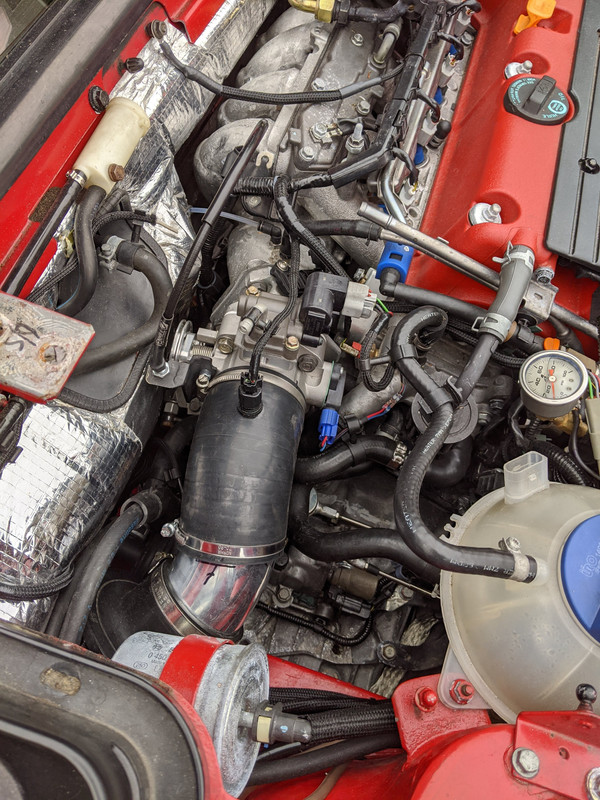
Performing Honda K24a3/AST5 6spd Conversion

I'm not sure how engine vibration would impact the TPS, he is saying the internal mechanism is compromised due to harsh vibrations typical when more rigid mounts are used?
His comment was that the stock K series TPS internals are pretty fragile. They do fine with the stock installs on the factory mounts but he claims a very high failure rate on swapped cars. He suggested swapping it out to start instead of waiting for it to fail and leave you stranded.

I guess a common option is to salvage a B series TPS from a junk yard but make sure to take the connector. K-Tuned sells an adapter kit to mount the B series TPS to a K series TB. You need to cut and splice in the B series connector as the are not the same. Their kit is about half the cost of their new K series TPS so I just sprung for the new one. The junk yards aren’t open now anyway and even if they were, it wouldn’t be worth my time to go looking for one. They say that their TPS has been beefed up and been designed for swapped indications.
 
First let me explain; unfortunately I have not been following this thread, in part due to not planning a swap, and in part due to trying to allocate my time on the forum and not be so distracted from the work I need to do on my own projects. So it was by way of a "search" for something else entirely that I happened to land on the posts between you and Tony about various cooling fan controllers. Therefore I apologize if this is outdated, has already been answered, or otherwise not relevant.

I have a few fans going into one of my builds that I've considered various controllers for. One is a small "computer fan" for the electronics like you added to your ECU. Another is a large Spal fan added to the intercooler as Tony did. And the third would be a pair of aftermarket radiator cooling fans with the AC system interlinked. Here are some thoughts I've had for them:

The small 'computer' fan I might just wire to run anytime the engine is running. It is so small and has so little current draw that I'm not sure it really needs to be kept off at any time. And I don't see how it would have any negative effects by running across the electronic board even when it's cool? The board has the ECU, relays, injector interface, aux fuse box, etc, and will live in the spare tire well. The board itself is aluminum and I will use heat sinks on the ECU and injector interface. So a fan may not even be needed, especially if I add a grill somewhere to vent the area. But I like having the extra insurance of a fan.

The intercooler fan may just need a simple temp probe/relay set up like one of the inexpensive generic radiator fan control units (the probe could be installed on the intake air tube). Or it might even be wired to also run continuously, because it also circulates air through the engine bay (ducted to keep the turbo heat away from everything else). So there may be some benefit to it running all along? Or I might have a "after run" timer to keep it running for a specified period after engine shut down to help cool the turbo? Or any combo of those. I'm not sure what options the ECU I'll be using has for this. It would be nice if the IAT switch could control it. And even nicer if the ECU can also do a 'after run' function. But I'm planning to use a MicroSquirt that is fairly limited this way.

The two radiator fans can be split, one controlled by the typical temp switch in the rad, and the other switched by the AC control. Or they can both be wired through a two-way temp switch in the rad; one coming on at temp 1 and the second also on at temp 2. Or I could use a more sophisticated controller like you discussed to ramp them up with temp and add fan speed with the AC on. Again, not sure what the ECU can do here.

Have you found any pros or cons to any particular arrangements? Any luck with the aftermarket controllers? There are all sorts of simple/inexpensive temp controllers that might work. I know a couple of companies make specific cooling fan modules that are capable of doing almost anything. I used one on another vehicle once and really wasn't that impressed with it. Plus they are really expensive and I'm not sure necessary. I'm leaning toward keeping it simple, even if not 100% ideal in the optimal world. But I'm open to thoughts.
 
I havent hooked up the controller I bought, so I really can't speak to it. The thermoswitch-controlled timer circuit I made for the bay fan has worked successfully.

For rad dual fan control, I will ultimately use a Volvo control relay which uses an ECU ground signal to govern hi/low fan speed, that the Honda ECU can provide.
 
Thank you, sorry to make you search so much. But appreciate the feedback.

The description reads very much like a few others that I've looked at, adjustable time delay for "on" or "off". There may be an advantage to delaying the "on" time to prevent a large load from several high demand components (like fans) all hitting at once, not sure. But I'd be more interested in the "off" delay, to keep the fan running for a specified time after shutdown. However it isn't clear, can it be set to start that delay after the power is switched off (vs when the power is first switched on)? Is that how you are using it?
 
Thank you, sorry to make you search so much. But appreciate the feedback.

The description reads very much like a few others that I've looked at, adjustable time delay for "on" or "off". There may be an advantage to delaying the "on" time to prevent a large load from several high demand components (like fans) all hitting at once, not sure. But I'd be more interested in the "off" delay, to keep the fan running for a specified time after shutdown. However it isn't clear, can it be set to start that delay after the power is switched off (vs when the power is first switched on)? Is that how you are using it? YES

That is exactly how I'm using it, works like a charm.
 
Today I made time to start on the TB revision. Using the 80mm TB, I've had a tip-in drivability issues that came back again.

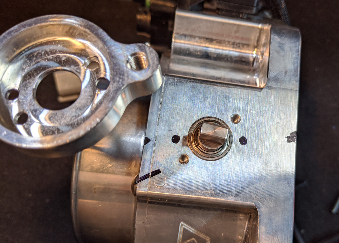
Chopped the flange off an Accord intake for the TB side, another flange off an RSX intake for the intake side. I don't want to weld the extension to the plenum, as it may interfere with the plenum removal .

IMG-20200805-091847.jpg


flanges welded after I determined the correct orientation to ensure bobbin & TPS clearance

IMG-20200819-180901.jpg


IMG-20200819-180915.jpg


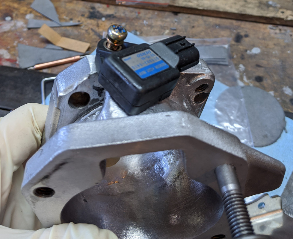
MAP will go on the adaptor - have to weld a bung

IMG-20200819-204221.jpg


Hopefully finish this tomorrow
 
Got the MAP bung figured out. Drilled & tapped the flange to use for the hold-down

IMG-20200820-170602.jpg


Had to seam weld the inside, couldn't get to all the external areas without messing with the bolt flange flats

IMG-20200820-170630.jpg


Revised the supplied bracket so that it fits the reverse orientation I need

IMG-20200820-170758.jpg


Used the 80mm setup to check offset

IMG-20200820-181709.jpg


Everything looks pretty good

IMG-20200820-182206.jpg


IMG-20200820-182217.jpg


Have to figure out an alternative air filter hose

IMG-20200820-182233.jpg
 
Last edited:
Got everything sorted out in terms of fitment, however the TPS won't zero

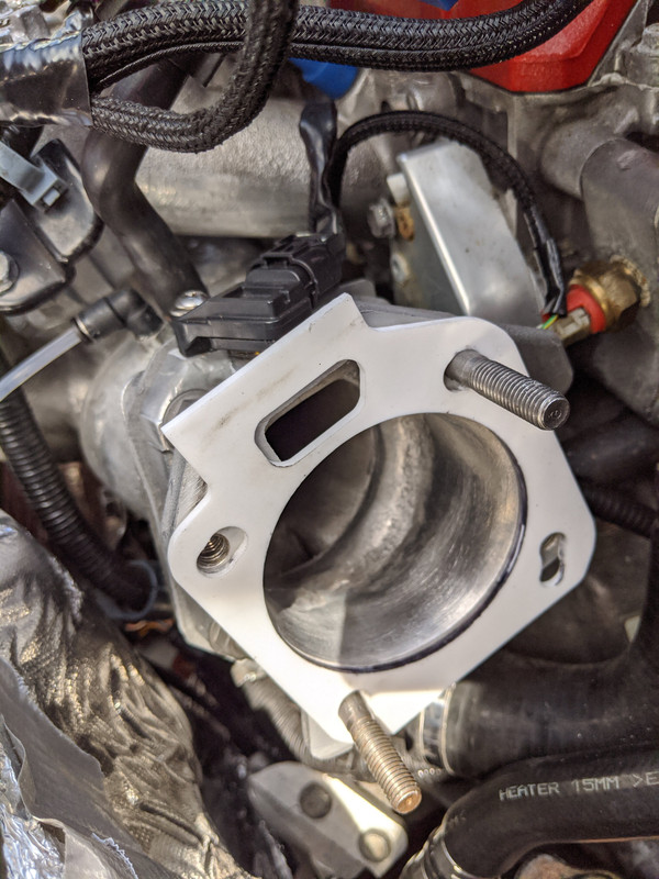
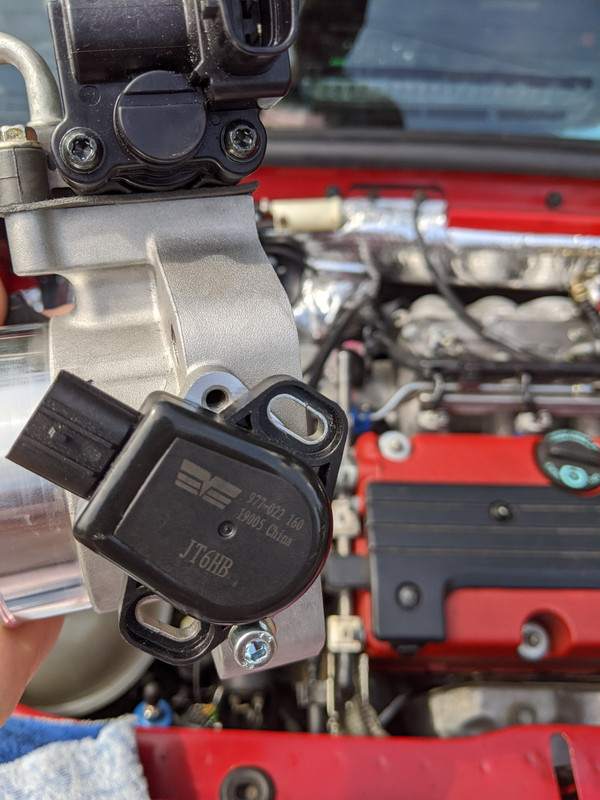
EDIT: What I found is that the TPS I bought (977-022, JT6HB), is NOT intended for the RSX Type S (JT7H, T42003), & judging from online pics, the inner "wheel" is set at a different offset, so that would explain why I can't get it to the proper base idle position.

TB adaptor finished.

IMG-20200821-120254.jpg


even with TPS pushed to end of range, I still have 30% in software

IMG-20200821-112148.jpg


IMG-20200821-112157.jpg


I did have the TPS + - (pins 1 & 3) reversed, which set a CEL

IMG-20200821-112811.jpg


so I reversed them

IMG-20200821-120311.jpg


If I move the TPS out of the mount window, then I can get to zero (and idle at proper rpm)

IMG-20200821-120408.jpg
 
Last edited:
So parts are not parts.

That’s frustrating without doubt.

Indeed. What makes it difficult to decipher is that Honda does not sell the TPS - they only sell complete TB assembly. So, part number listings tend to be a touch sketchy. I'm basing my assessment on available stock photos that appear to show the orientation change - I'll find out on Sunday

The key way is spring loaded - so the pics have to show it at full stop. When you install the TPS it is fitted to the shaft then rotated at least 45º or more to get it into the operating window where the mount ears are set


RSX type S - Amazon listing detail

:D
Amazonlisitng.png

Dorman 977-022 (JT6HB - what I have)

Dormann.png


RSX Type S eBay listing detail - this one could be a mirror image (flipped pic) of mine, since it looks the same, just reversed

eBaylisitng.png
 
Last edited:
I suppose in the worst case (if you can't find another TPS that works) you could always make up a bracket to allow it to be mounted in this orientation...

Indeed. I am trying to avoid that though, on the 80mm TB I modified the mount plate to allow for repositioning the TPS, and it's quite possible that in so doing I created a potential bind tht impacts the TPS from properly returning to base position. I did not use any sort of jig to ensure the new holes are properly centered around the pivot. It seems OK, but since I have had problems with settings not staying put, I dunno. Could also be cheap parts, since the TPS is not sold OEM. Just trying to remove all the extraneous variables I can to get this resolved.

IMG-20200122-171144.jpg
 
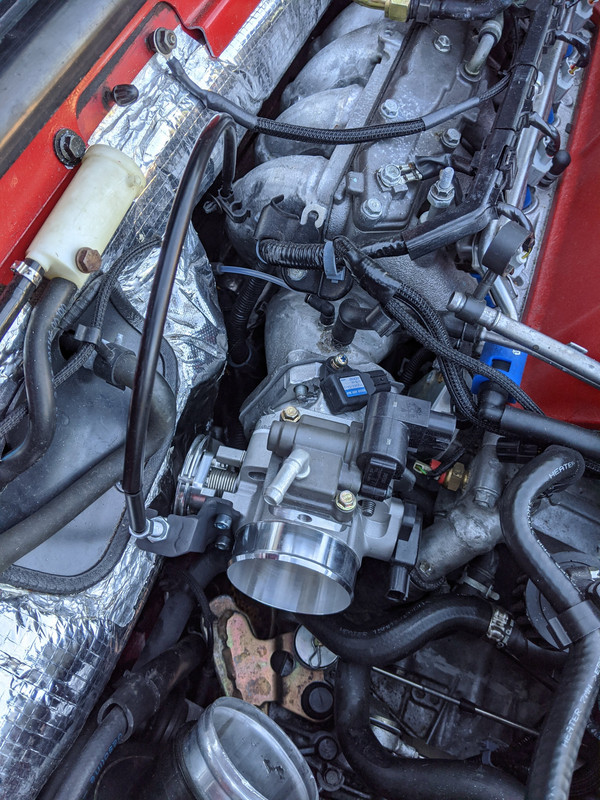
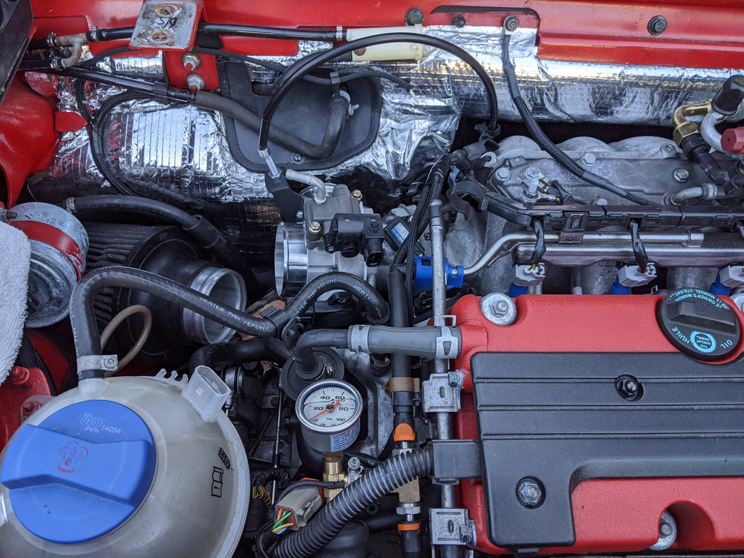
Got the revised air filter intake pipe & IAT sensor fitted. I have many 45º, 90º & step silicone couplers and sections of 2.5 - 3..5" piping from the variety of intercooler piping setups I made over the years I had my old Volvo wagon. Still waiting for the K-Tuned TPS, hopefully here Friday. The unit from Amazon is unusable - not sure what it is meant for, sure ain't the Type S version :mad:

IMG-20200826-185914.jpg
 
Last edited:
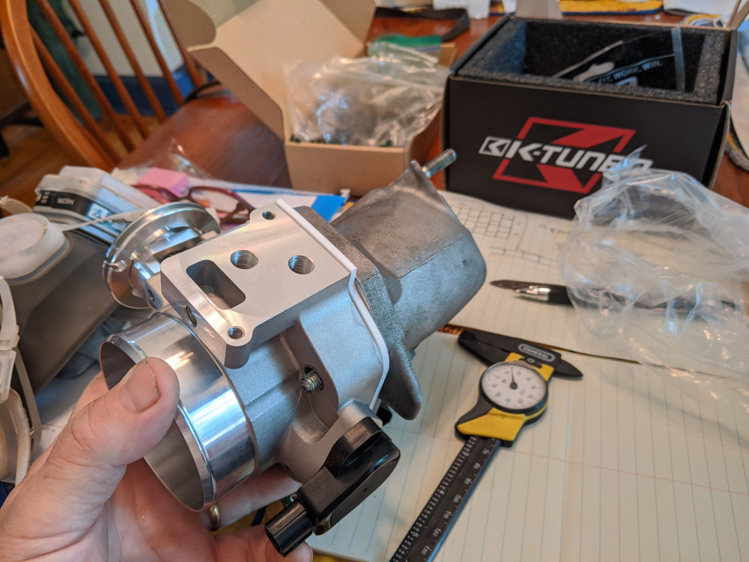
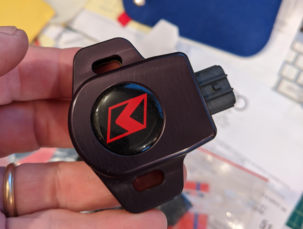
K-Tuned TPS finally came - I'll try to get it installed before school starts on Tues. Not cheap, but supposedly better constructed than the typical aftermarket.

IMG-20200829-181439.jpg


clocking is the reverse of what I had

IMG-20200829-181446.jpg


just a 'billet' cover over the JT7H TPS - this cover may be too bulky to install in my setup

IMG-20200829-181452.jpg


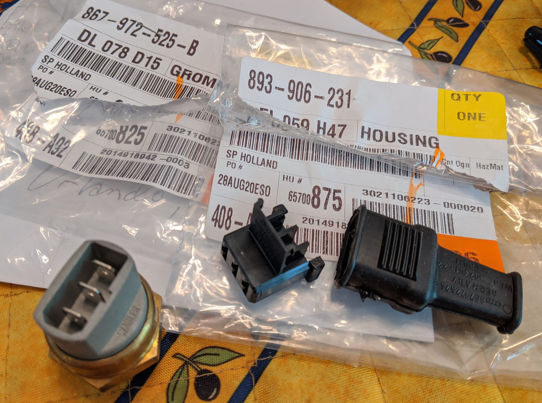
Also got the VW 3 pole connector & boot (to go with the 3pole VW lower temp fan switch) from the local Audi dealer (topic in this thread)

867-972-525-B grommet . 893-906-231 housing 25195948175 lower temp 75/82ºC sender
IMG-20200829-152414.jpg
 
Last edited:
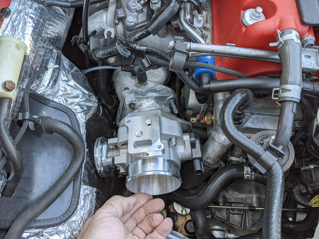
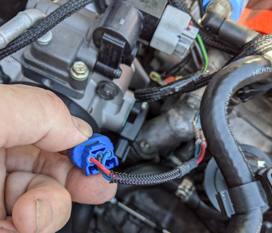
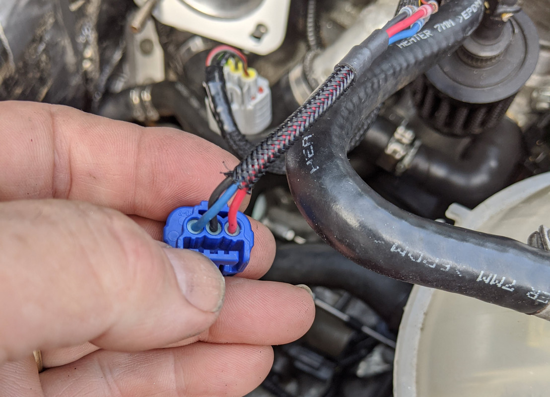
K-Tuned TPS installed, sets properly to 0º throttle angle at rest stop without anyway issues. I had to remove the TPS connector from the harness, and repin for the RSX type S switch - and dropped the blue connector down into the bay... took me 20min to find it, had to jack the car up in the rear & hunt for it. Finally found it wedged into the balljoint/control arm.

IMG-20200831-154416.jpg
 
Sorry to digress, on the VW/Audi connector, what type of female terminals go into the plastic connector?

Something I should know but don’t.

Thanks.

I am about to get very familiar with Cycle Terminal as I am rewiring my tractor from end to end as well as redoing my coolant system on the X.
 
Sorry to digress, on the VW/Audi connector, what type of female terminals go into the plastic connector?

Something I should know but don’t.

Thanks.

I am about to get very familiar with Cycle Terminal as I am rewiring my tractor from end to end as well as redoing my coolant system on the X.

CycleTerminal is great. He is also very responsive to emails - I sent him pics of some conenctors/terminals I could not identify. The VW Fan switch connector uses the standard crimp-with locking tab spade terminals - 6.3mm I think they are, I've never actually measured them. I would only use the coated/tinned terminals there - not the plain brass/copper variety.

Screen Shot 2020-09-01 at 8.33.18 AM.png
 
Last edited:
Back
Top