So the dash mods are done.
Thread here.
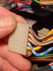
Test fitting, removed after this to tidy up all the wiring.
So, now I need to fix up the wiring under the dash on the right before I pull the heater box. There is a big mess, I have added a bunch of stuff over the years, and the wiring criss-crosses back & forth, I need to separate the various looms, and reroute the central lock, keyless entry, remote trunk release, etc., so that they all follow the stock looms. To achieve this, I have to add a bunch of wiring, and add connectors where needed to separate the harnesses.
I want to repurpose the unused stock relay locations for seat belt, timer, headlight covers for some of the relays I had added (trunk release, park & interior lights flash w/lock & unlock). To do this I needed to follow the wiring manual & figure our which wires I can repurpose, and which would need replacing. So far, every wire I have checked is a different color than the diagrams, and routing/relay connections seem to alter also

So, I've removed the entire box, and started to map out the pins from the relay connections to the I/O on the back of the box.... I'm not good at spreadsheets, etc., so I'l prolly just write it all out on a legal pad.
Seat Belt & timer relay wiring
Compared to diagram
ALL the connections - already tidied the flasher & delayed interior lighting
NOTE: This is the order of letters embossed on the box - diagrams use a different designation (!) see Rodgers post
top row
O F Q S L H I [
F vacant]
Middl
e G B
Bottom Row
E P C D A R V N [
V vacant]
I can't find a schematic anywhere that lists the pinout for the connectors, so I have to number & label them all, then ohm out the circuits that I need to know about.
Top - L-R : #1 is bottom connection within any connector
NOTE ; ANY wires that look turquoise or blue-green are actually GREEN.
O 4pin connector - to front of car
F -vacant
Q 3pin
connector
S 6pin connector - dash harness
L 6pin connector (goes to rear of cabin)
H 10 pin I/O for aux 6 relay set
I 10 pin connector (shown upside down - BN is 1)
Middle L-R
G 8pin I/O for aux 6 relay set
B 8pin connector - rear cabin harness
Bottom L-R
E 12pin connector - rear cabin harness
P 8pin connector - goes to front of car
C 8pin connector - goes to front of car
D 12pin connector - dash harness
A 12pin connector - dash harness
R - BN output - defroster
N- 2 wire R , R-SB input
Additional Relay Set H & G connectors
E B L
To Rear
O C P
to front