Performing Honda K24a3/AST5 6spd Conversion

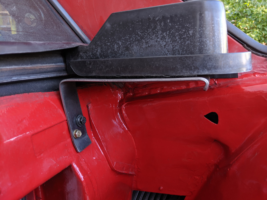
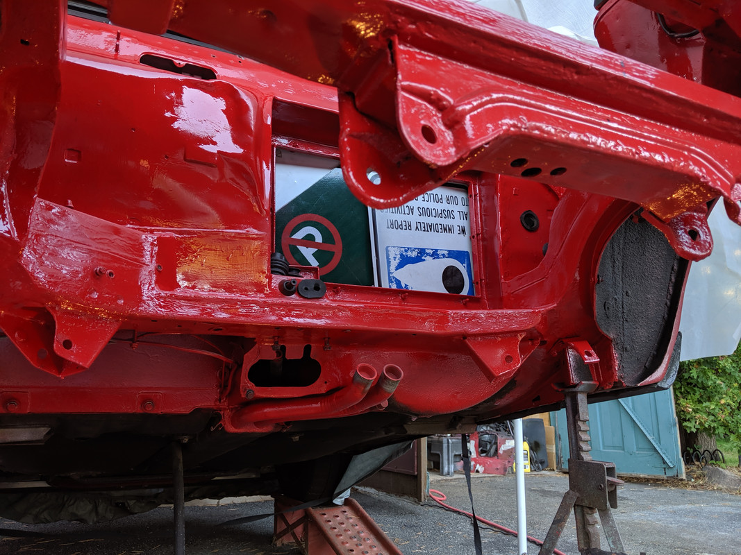
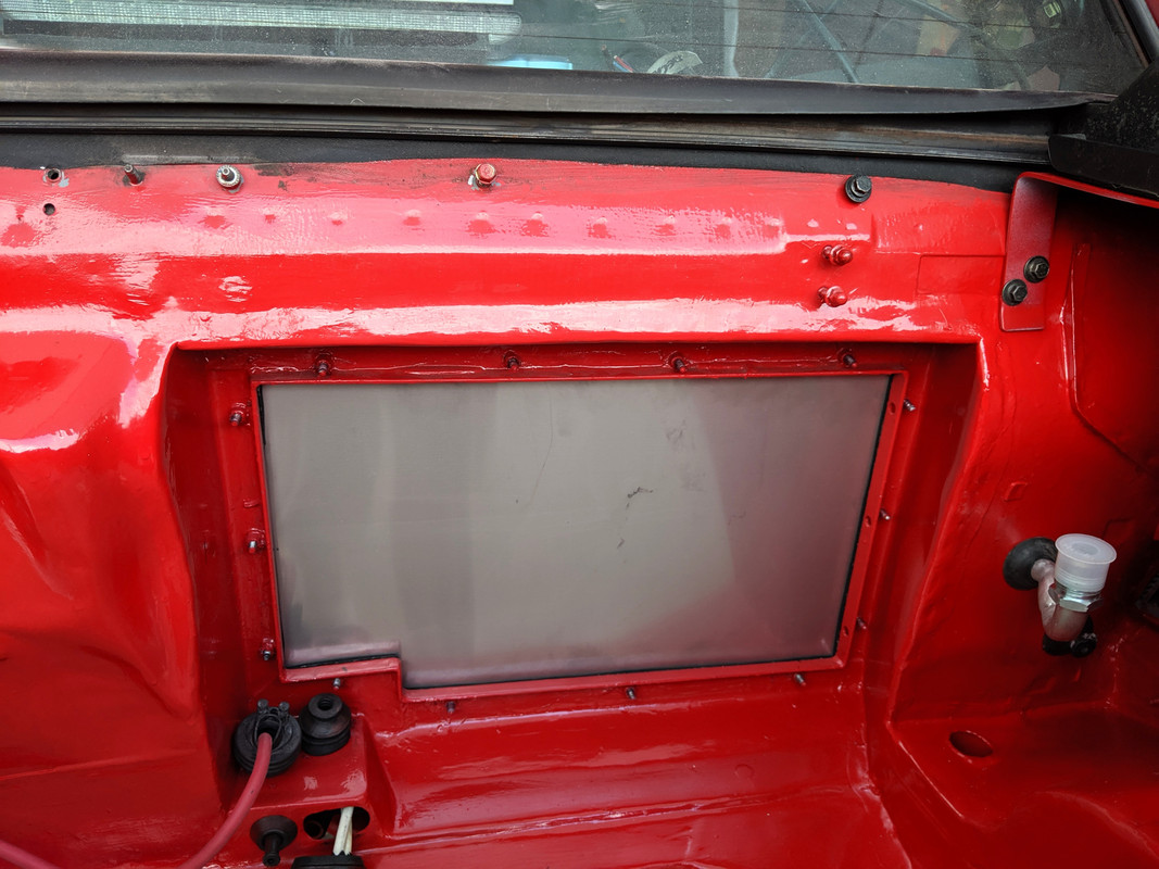
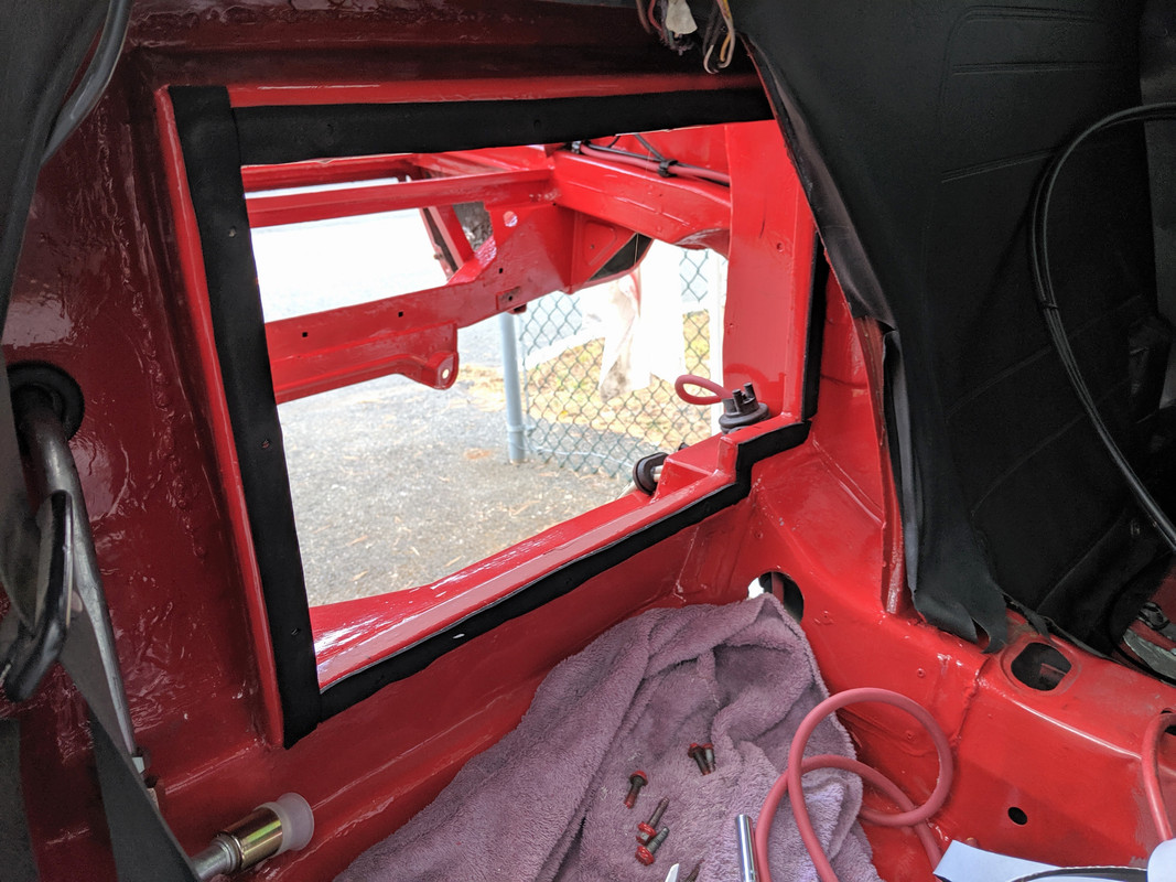
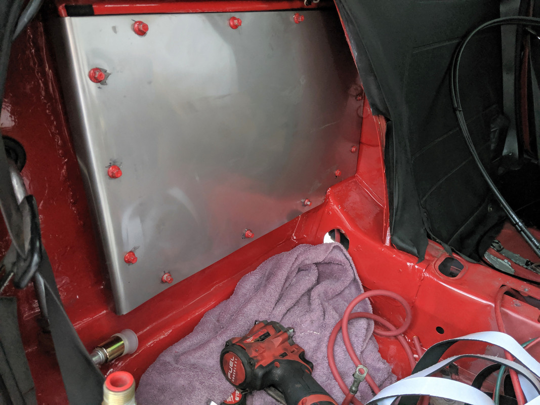
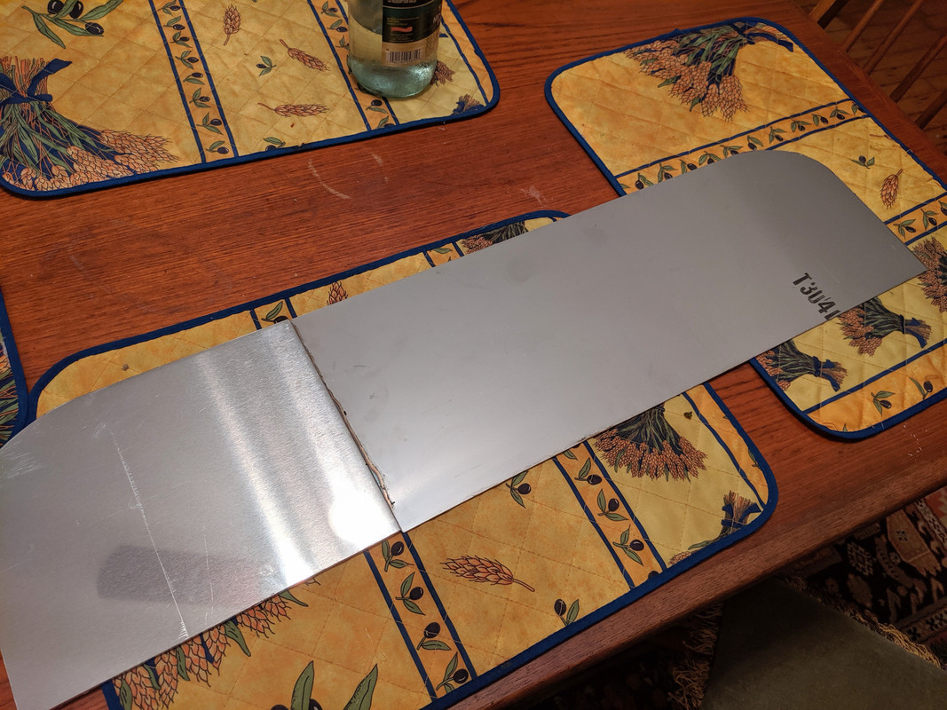
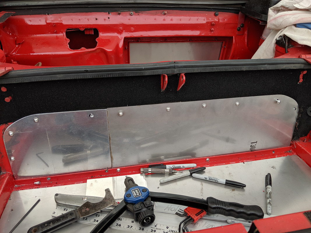
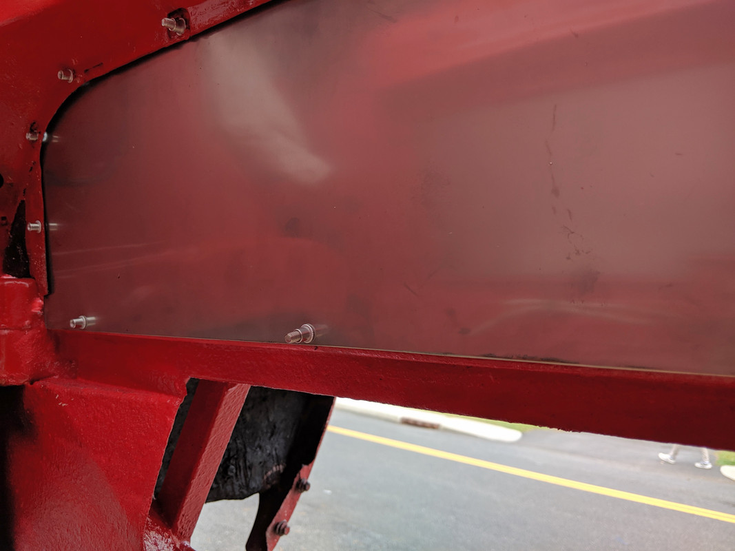
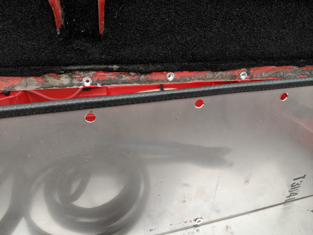
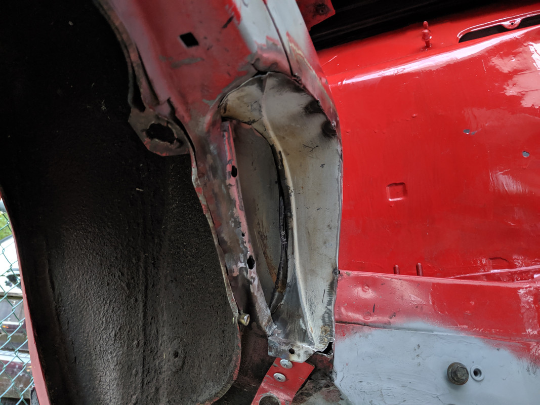
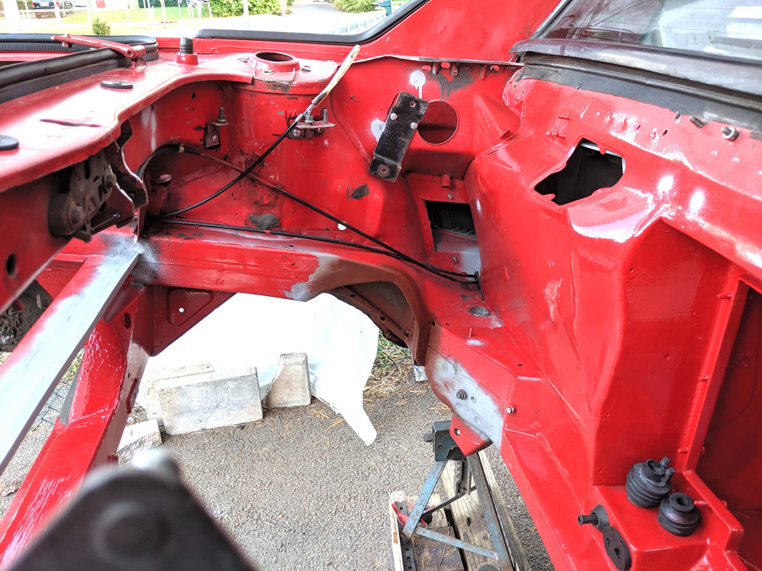
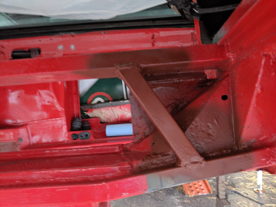
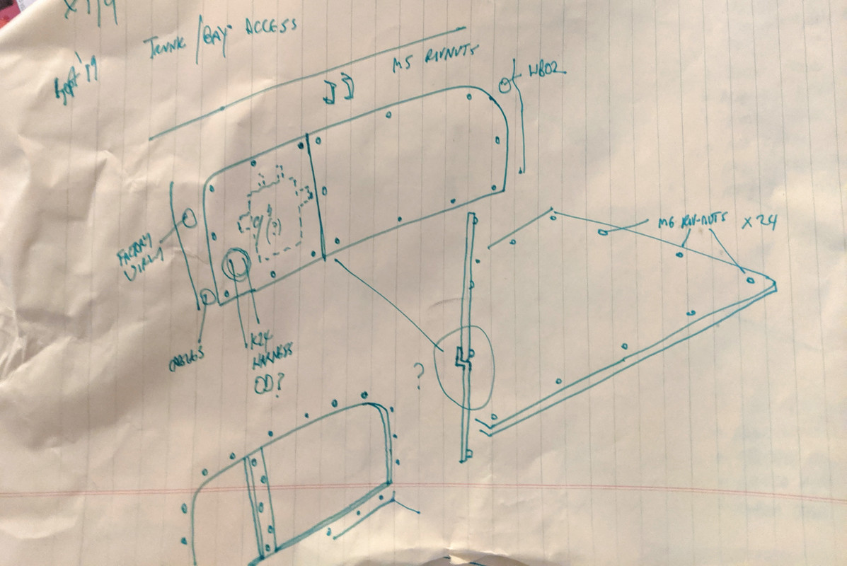
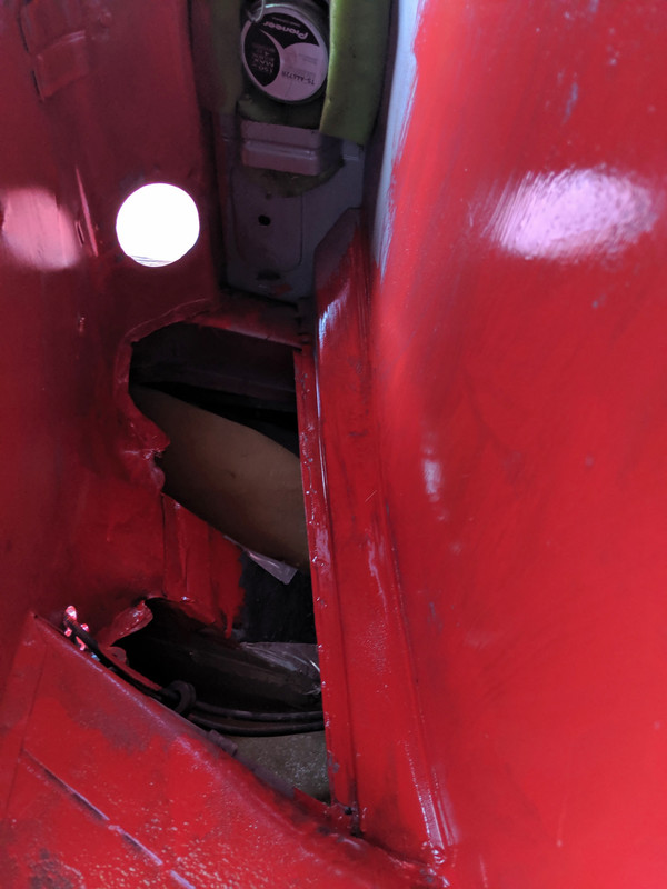
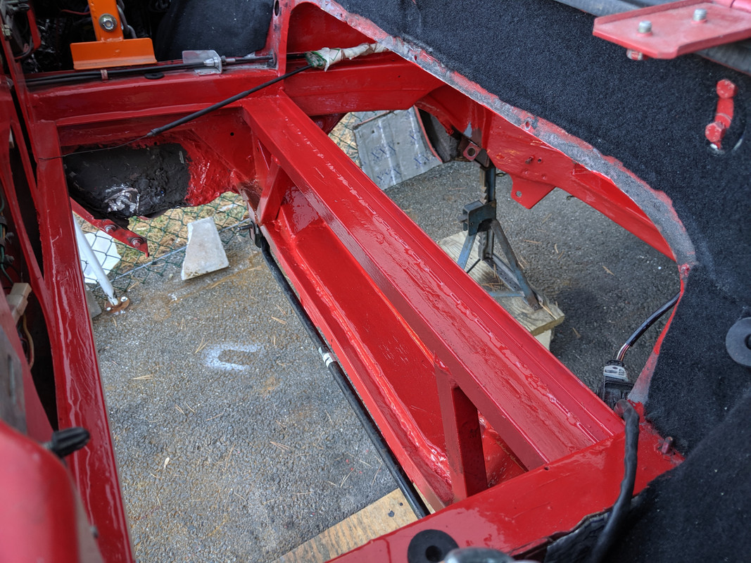
Welded & caulked the lip that will be for securing the bottom edge of the bay/trunk access panel. Have to add end junctions and clean up the existing upper ridge.

IMG-20190925-181055.jpg


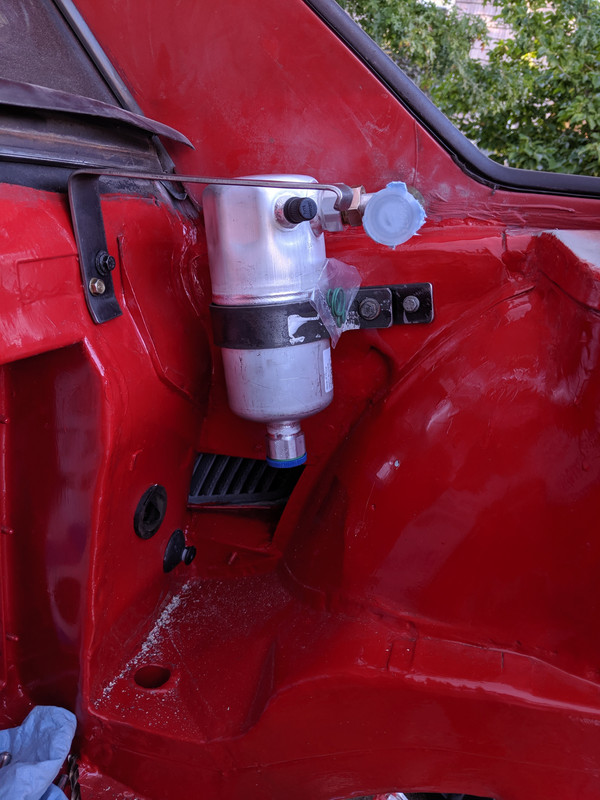
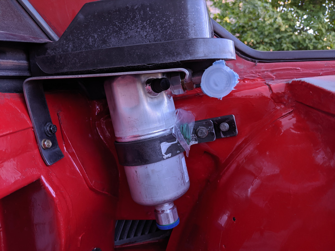
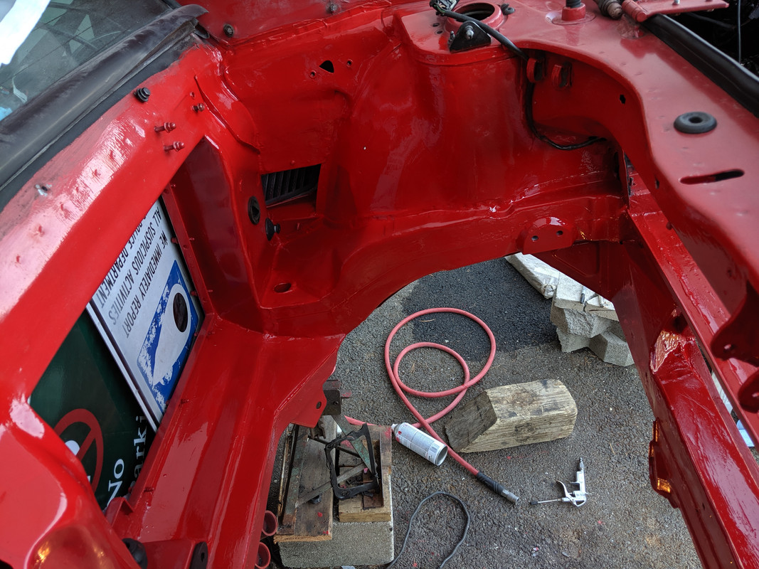
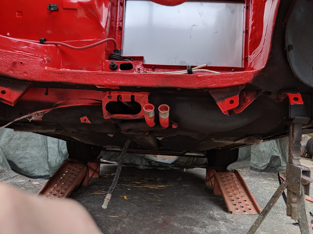
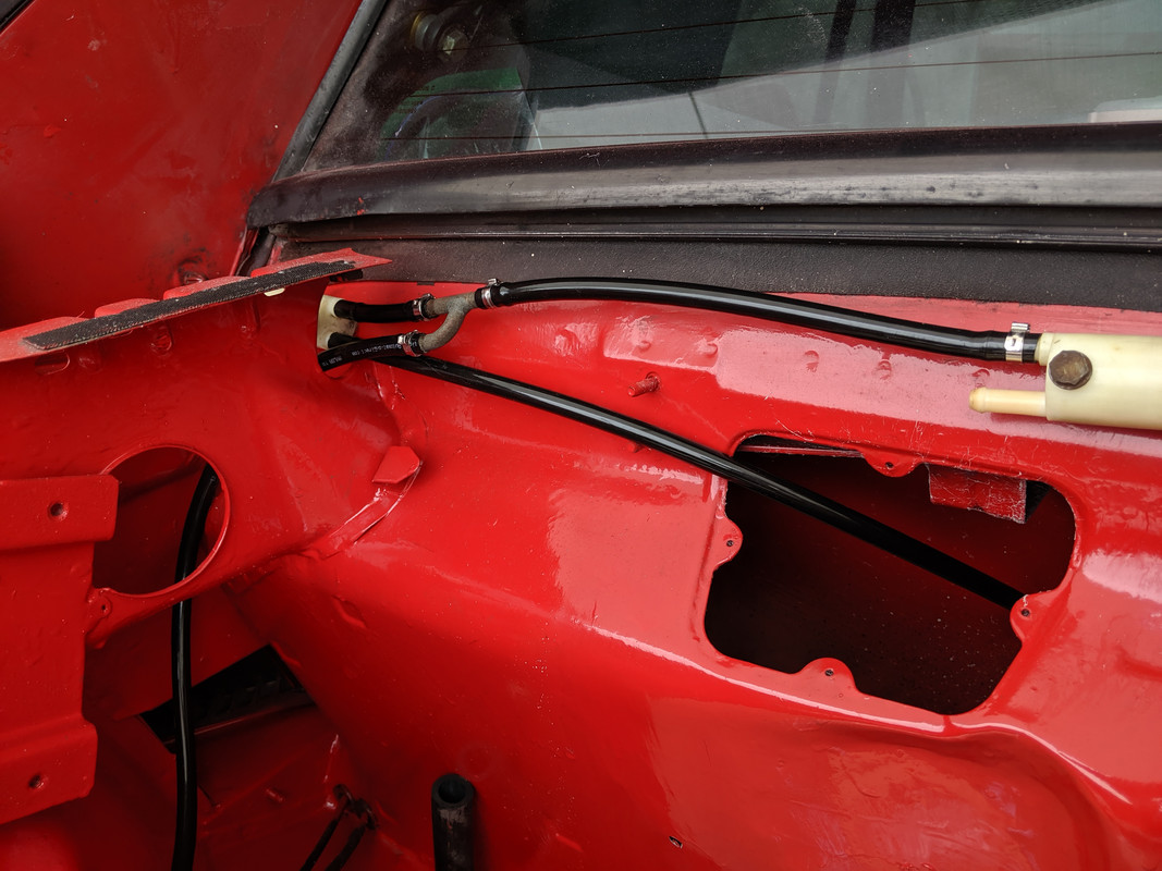
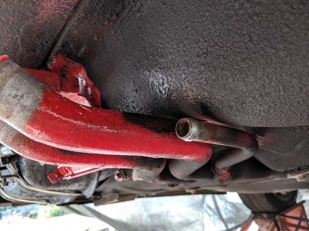
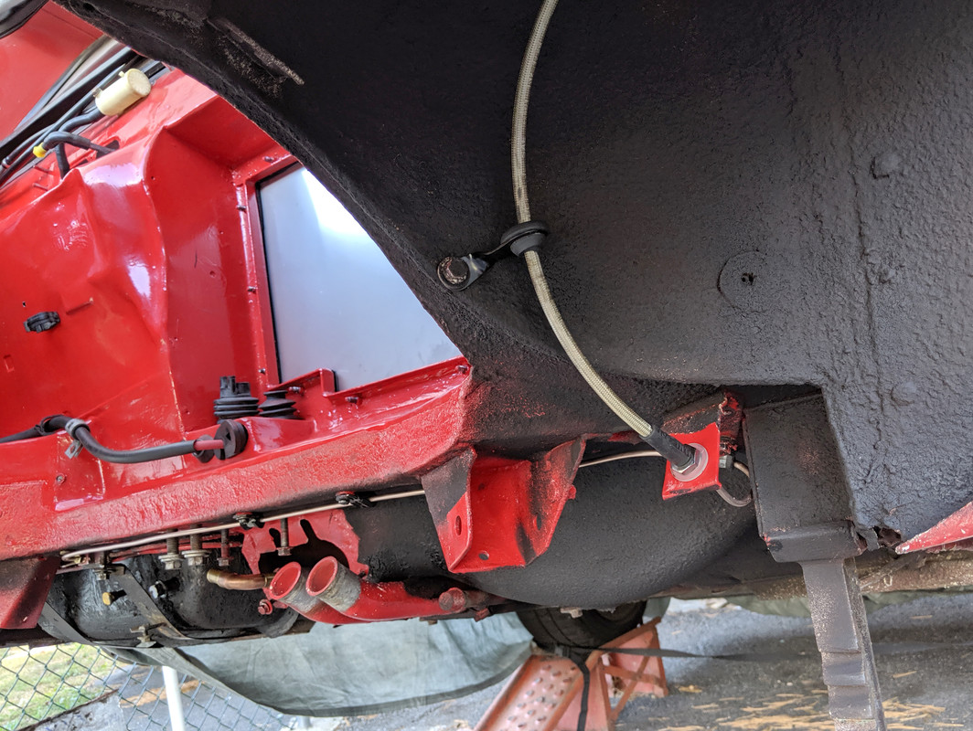
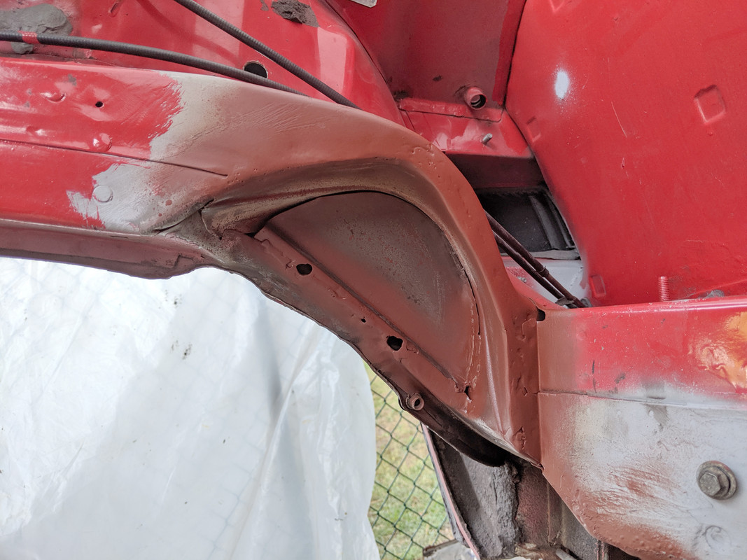
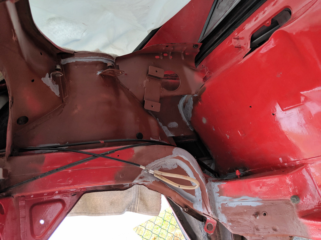
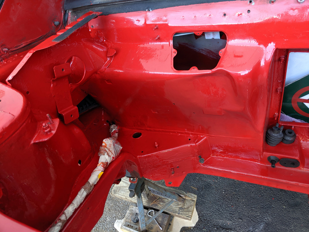
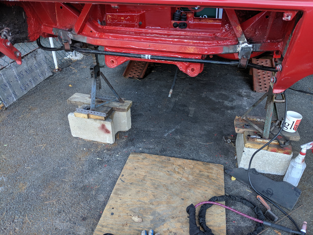
More paint on the right side. 3M Rocker Schutz folowed by undercoat will finish the right side.

IMG-20190925-181105.jpg


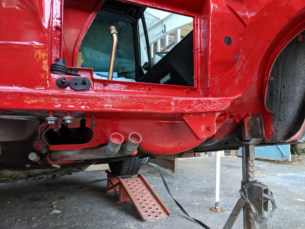
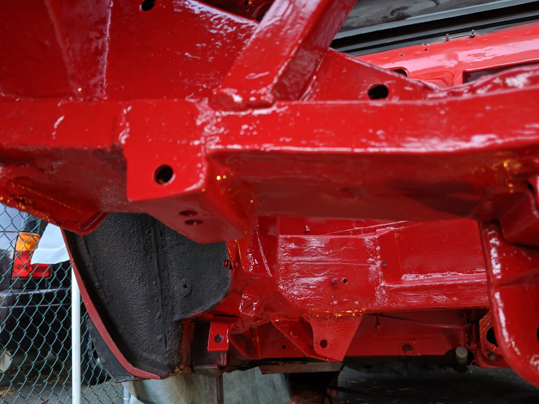
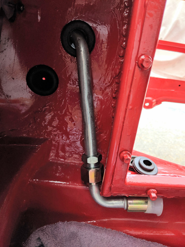
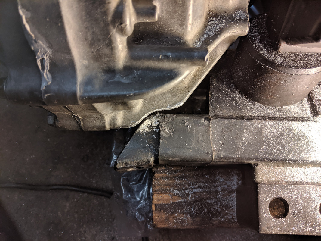
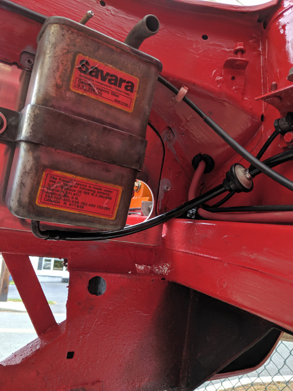
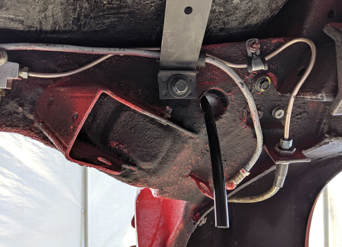
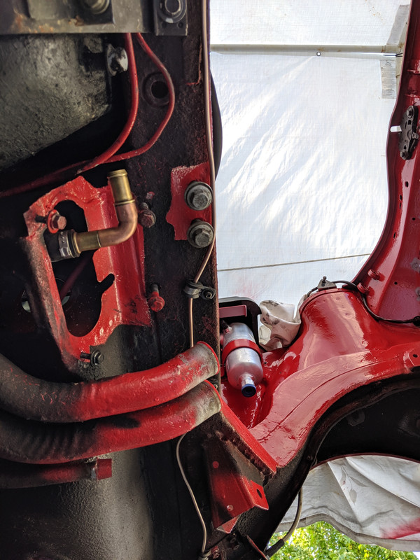
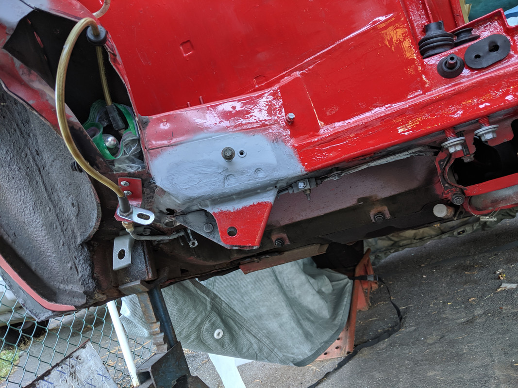
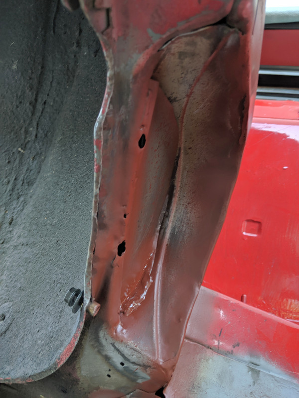
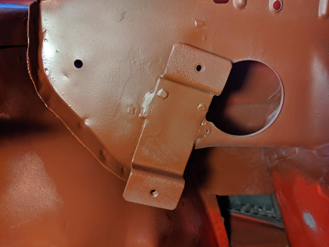
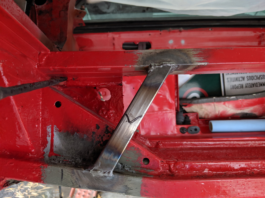
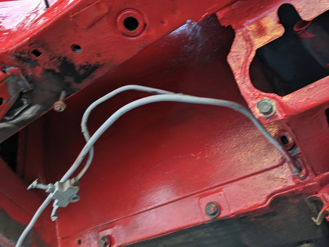
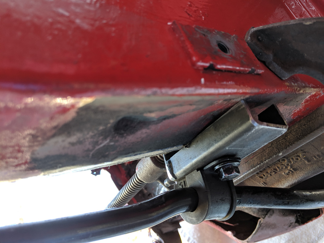
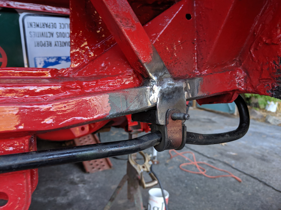
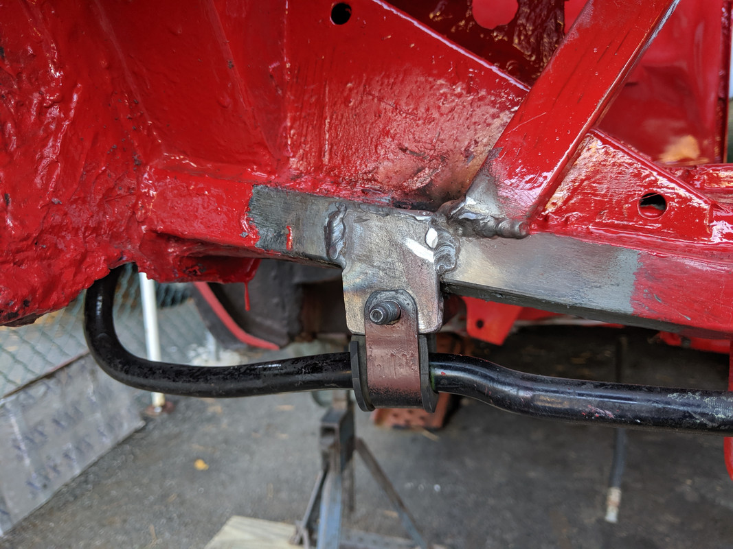
Welded the repair needed on the outer face of the rail here, and seamed the control arm mount. Have to fix the rust hole underneath & weld the clutch line bracket to the rail, then do the left cutout for the trans

IMG-20190925-181101.jpg
 
Removed the clutch & brake lines so I can do the work around the left C/arm mount. Cleared out the gas tank compartment of crud, cleaned with turps in prep for paint. After that, I started on the left cut out. First I hammered out the arch further to the left, as Rodger had commented the outer skin was still kinda close the trans casing. I used sections of panelling I cut off the parts car, pieces that have stepped ridges in them to add a little extra rigidity to the panel. Tacked around the perimeter for now.

IMG-20190926-183534.jpg


IMG-20190926-183527.jpg
 
Last edited:
Slow going. The underside welds are really awkward. For much of them, I have to sit on the ground & weld above me, which is definitely less than ideal. In that position, I have to use my knee to operate the foot pedal, pain in the butt, or rather, my lower back.

Used part of the old reservoir support bracket to fix the rust hole

IMG-20190927-181642.jpg


Still have to seam the inner edge to the outward vertical plate (and fill those two holes), primed for now as I will be out of town until Tuesday.

IMG-20190927-181650.jpg


IMG-20190927-181656.jpg


IMG-20190927-181735.jpg


Primer dots are where I chopped off all the studs
IMG-20190927-181743.jpg
 
Last edited:
Reasonably productive day today.

Started by cutting out the lower section of the left trough. I've been mulling over this since Friday. I wanted it more open to allow air to be drawn in to the filter. Since it's going as pictured, there is not much space around the filter

IMG-20190818-164459.jpg


I decided to leave the vertical section, since it both secures the filler neck, and my new filter location, and provides the seat for the trim cover, I really didn't want to cut it all away, so I removed all the lower section.

IMG-20191001-184021.jpg


I got the fuel filter bracket welded

IMG-20191001-184105.jpg


The coolant reservoir brackets welded

IMG-20191001-184101.jpg


IMG-20191001-184015.jpg


and finished welding the left cutout. What a pain it was. Still vacillating on whether to beef up the frame rail to the rear of the cutout. I'll caulk the welds later

IMG-20191001-184032.jpg


Still have to finish welding the pass through tube, the rear side of the left c/arm mount and the clutch hard line bracket.
 
Last edited:
Got a little done today. Had heavy rain, so only a short time outside.

Caulked all the seams on the left

IMG-20191002-143738.jpg


added ribs from the upper crossmember to the lower

IMG-20191002-143723.jpg


IMG-20191002-143727.jpg


Moving inside I did some little things - welded a recess skin for the eBrake cover to clear the MWB subframe

IMG-20191002-155116.jpg


IMG-20191002-155127.jpg


IMG-20191002-155127.jpg


Started on the rear swaybar mounting. Doug shared his design with me, so it will be similar to Rodger's setup, using an Acura Integra rear bar. Bent the bushing mounts, made the U channel inserts that will retain the bar

IMG-20191002-161050.jpg


U channel (welding 1.5" angle iron & then cutting at the required staggered offset) will be welded under the crossmember. Bending the bracket allows it so sit as close as it can to the crossmember - will mount basically like this (will have vertical end plate that is welded to the added square tube on my crossmember.

IMG-20191002-161614.jpg


My access panel will be in two parts - one to hold the charcoal cannistor & passthrough for K24 engine harness - then the main section

IMG-20191002-180933.jpg


Probably going to step the cover for the overlap, rather than make a fixed vertical divider.

IMG-20191002-180940.jpg
 
Last edited:
Pouring rain all day today, so had to work inside the garage when I got home. I worked on the sway bar brackets, that ate up the 3 hours I had available.

Welded the angle iron into a (1.5") box, then cut it at an offset for staggered sides 3/4" & 5/8" with a hacksaw. I need to get a metal blade for my 10" table saw, would have been so much easier. I then welded the end plates in place, only to find I had not reversed the offset on one, so I had to add an 1/8" strip on the 5/8" side & file down the other....

This is where I'm at - they are ready to weld to the crossmember, assuming the weather lets up for tomorrow after work. I'll finalize the vertical tab once I position the bar & brackets on the crossmember.

IMG-20191003-171508.jpg


Parts:

had to thicken the underside of the insert nut plate with another 1/8" plate, so that when installed the bushing bracket is tensioned, compressing the bushing slightly, otherwise the bushing flat was merely flush with the mount plate.
IMG-20191003-171512.jpg


started figuring out the aluminum (1/8") access panel - approx 31"x8" overall dimensions

IMG-20191003-173201.jpg


Will bolt in from the trunk, and then have a lip (probably short stitch weld on the backside to avoid distortion) to which the other section will be secured. Narrow section is approx 9" wide - the charcoal cannister is 7" with bracket, and I need to make a hole for the K24 ECU grommet below & to the left, about 3", I think.

IMG-20191003-173213.jpg
 
Last edited:
Worked on the swaybar mounting & some paint over the worked left side.

IMG-20191004-165343.jpg


Inside the tank compartment (still have to wled the arm mount, dark area left of pic)

IMG-20191004-173355.jpg


Inside gas tank pocket

IMG-20191004-173410.jpg


IMG-20191004-173418.jpg


paint on new crossmember

IMG-20191004-173846.jpg


Clamped bar centered in place to check mounts

IMG-20191004-165128.jpg


IMG-20191004-165131.jpg


Have to add approx 1/8" filler strip on outer edge. The bushing pivout area of the bar is not parallel to center section.

IMG-20191004-165220.jpg


IMG-20191004-165225.jpg


End plates welded

IMG-20191004-172813.jpg


IMG-20191004-172817.jpg


IMG-20191004-172819.jpg


Tomorrow I'll fit the control arms & figure where the endlink brackets need to go (or not :D).

IMG-20191004-173834.jpg
 
Last edited:
A question about the rear access panel. I have been wondering about this for my own cars, what if the access panel lived on the engine side of the bulkhead and had captive nuts in it to take the fasteners coming from the trunk side.

The reason I bring this up is that a panel on that side will be easier to seal from a weather standpoint as there is an overhand above and any liquid flowing down would drip back into the engine bay rather than the floor of the trunk.

I don’t know if this improves or worsens the access issue you are trying to solve. This is something I hope to try on my red car which has had water ingress issues in the past. Using rivnuts or PEM studs would both be good fastener approaches depending on what the access and removal space is.
 
Finished welding the swaybar mount brackets, got the left side mount bracket welded, and everything body-caulked and painted. Should be able to put the motor back in shortly. Have some misc wiring to address while I have better access first.

Made the bracket for the right cap
IMG-20191005-154941.jpg


and bracket for the AC accumulator

IMG-20191005-164344.jpg


IMG-20191005-164325.jpg


2nd coat of paint on left side

IMG-20191005-175747.jpg


IMG-20191005-180633.jpg


Looking pretty finished overall

IMG-20191005-175806.jpg


IMG-20191005-175752.jpg


just have to paint this

IMG-20191005-180638.jpg
 
Spent an hour or so on the AC accumulator positioning & hose connections. Flipped the mount bracket I made (added new rivnuts) so the compressor feed hose could run along the bulkhead. Wanted the accumulator to sit more level also - I've never seen a factory install where it wasn't properly vertical.

This combined fitting is now #12 MOR, to #10 hose. Have to weld the two together.
IMG-20191006-144859.jpg


This one will be #12 MOR at both ends. Have to weld it where my hand is holding the two halves. This will run through the firewall hole behind my left middle finger & down the side of the opening, and connect to the factory #10 inside hose (with an adapter hose end going from #12 FOR to #10 hose.

IMG-20191006-144849.jpg


Going to end up like this:

IMG-20191007-122425.jpg
 
Last edited:
A question about the rear access panel. I have been wondering about this for my own cars, what if the access panel lived on the engine side of the bulkhead and had captive nuts in it to take the fasteners coming from the trunk side.

The reason I bring this up is that a panel on that side will be easier to seal from a weather standpoint as there is an overhand above and any liquid flowing down would drip back into the engine bay rather than the floor of the trunk.

I don’t know if this improves or worsens the access issue you are trying to solve. This is something I hope to try on my red car which has had water ingress issues in the past. Using rivnuts or PEM studs would both be good fastener approaches depending on what the access and removal space is.

Sorry I missed this post. I'm going to add an 1/8" closed-cell foam seal strip to the panel opening. I know that still leaves a lip that water can potentially work it's way past, however putting the panel on the bay side just seems like a PITA when it comes to removing. My original panel and opening were both rusted along the bottom edge, but it did not seem as though there was ever a seal there, and the lower opening lip weld seam was not sealed, so water sat in the joint. Mine hopefully will not have that concern.
 
Not much accomplished today. Not feeling well the past couple days, and the weather sucks to boot.

Got the AC pipe welded.

IMG-20191007-163211.jpg


Inside, this will attach to a #10 hose, then connecting to the stock #10 hose, after I cut off the formed metal section of the stock hose & replace that with a #10 MIOR fitting.

IMG-20191007-163228.jpg


Besides that, all I got to was reinstalling the engine cover latch & cable, and laying out the ancillary battery cable that will feed all the ECU needs. It will be sheathed and combined with the stock harness feeding the rear end.

IMG-20191007-181038.jpg
 
Last edited:
Worked on the cover panels. SS T304 .048"

21x13" aperture cover

IMG-20191008-180649.jpg


Closed cell foam seal on the lip. Used a die punch to cut the bolt holes first, so the bolts won't twist the foam when inserted.

IMG-20191008-175738.jpg


IMG-20191008-180707.jpg


IMG-20191008-180745.jpg


Two part trunk access panel. Left side will technically be removable, however it will house the ECU pass through and the charcoal canister. Right side where the heat of the header is, is SS.

9x7.5" Left Aluminum 21x7.5" Right SS T304L .048" (18ga)
IMG-20191008-194403.jpg


Trunk floor 31.25x13". Also SS T304L .048"

IMG-20191008-194414.jpg
 
Last edited:
Another cold & rainy day, so no paint/undercoat work. Laid in the trunk panel to check fit. Have to shave 1/8" or less off last 1" of inner ends, the crossbrace welds are interfering with it laying flat.

Futzed around with the rear sway bar, stripped my Fiat transaxle,

IMG-20191009-184301.jpg


Got the AC #12 lines welded by my machine shop. I wasn't having a good time with it at all.

IMG-20191009-183619.jpg


Worked on the forward trans mount bracket

IMG-20191009-172706.jpg


IMG-20191009-172711.jpg


ground back the webbing on the rearside of the transaxle, where it would be hitting the subframe under load

IMG-20191009-183004.jpg


IMG-20191009-183419.jpg


May need to go a touch deeper in the dip

IMG-20191009-183419.jpg


Besides that, I did a little prep work on the motor, installed the plenum gasket, some hose clamps, etc.
 
Last edited:
Lots of little jobs, that is what this all is. I went on the roof and replaced some shingles. Long story about that.

You are making good progress.
 
Today temps got back up into the mid 60's, so I was able to get the stone guard & undercoat on.

IMG-20191010-173737.jpg


After that I worked on the trunk/bay access panel(s). I decided to partially use Karls' idea of putting the panel on the bay side of the opening :D

Rivnuts along the top & sides of the opening, and along the bottom of the panels, so the panel is tucked behind the lip at the bottom, and inside the lip at the top.
IMG-20191010-173716.jpg


IMG-20191010-173726.jpg


Got thin edge molding from M M Seals so I don't slice myself on the SS panel sections.

IMG-20191010-180857.jpg
 
Last edited:
Cool, that worked out to ensure the water stays on the engine side better than what I had thought about. Nice job. I presume your solution is possible due to the add in angle you added across the bottom of the opening.

Did your car have a reflective barrier chunk of insulation on the engine side of the old access cover? Adding that will greatly reduce the heat transfer from the header. I recently took my cover out on my ‘85 which had never been off in its life, it stuck badly to the undercoat so it was torn up pretty badly despite my efforts to the contrary. I need to peruse Granger to see if there is a semi rigid board that can be (or comes) wrapped with reflective material.

Looking good!

It fits cos I didn't reconnect the vertical side panels to the new lip. As long as the replacement panel is flat, it will slide in-between.

My old cover didn't have any insulation. I may add that after, since I bought a large panel of 1/4" adhesive backed insulation.

Put the gas tank back in, and put together the evap setup. Black tube is the overpressure vent, I'll trim the length when I finalize the layout. Heater hose is the other tube.

Have to make the left & right under frame brake lines, to connect to the new flex hoses.
IMG-20191011-173930.jpg


Replaced hoses with 10mm ID Nitrile line. Won't ever wear out. All connections will be secured with 10.5mm oetiker clamps, although I don't think it's really necessary.
IMG-20191011-151729.jpg


Tucked vent line behind panel, since the bottom is open that works for me.
IMG-20191011-151732.jpg


I soldered the right tank vent tube back in at the wrong angle - it doesn't lean toward the left, so I'm going to need an elbow to connect that tube.
IMG-20191011-175115.jpg


Mounted the cannister on the backside of my new panel, with 1" spacers. Cut 2.25" hole next to it for the ECU harness.

IMG-20191011-164336.jpg


IMG-20191011-164343.jpg
 
Last edited:
Got the heater return feed side sorted out.

Flipped the stock hose inside the tunnel. Cut it where I need it to exit the old shifter rod location. The hose on mine is still in really good shape, no swelling or softening, so I'm going to reuse it.

IMG-20191012-124459.jpg


Took an elbow from an old Volvo heater hose, added an olive on the side that normally goes into the firewall junction

IMG-20191012-124314.jpg


Volvo bulkhead harness grommet repurposed

IMG-20191012-124309.jpg


Outer connection will have a Oetiker clamp also, since this isn't something that needs to come off on a regular basis.
IMG-20191012-124303.jpg


Also sweated an olive on the cut heater return tube, to make sure the hose fits snug there also.

IMG-20191012-124407.jpg


With that out of the way, I made the two under chassis brake lines. Left side. Had to make this one twice, I had trouble with the 2nd flare twice, and then pipe was too short to rework. I made the second one longer in case I had the same issue. The flare tool I have doesn't clamp on either side of the pipe in perfect alignment, so some flares end up offset & therefore unusable.

IMG-20191012-153129.jpg


IMG-20191012-153147.jpg


Right side

IMG-20191012-153139.jpg

IMG-20191012-153200.jpg


Started playing with the fuel line arrangement. Gonna need some finessing to work with the air filter.

IMG-20191012-183731.jpg


IMG-20191012-183713.jpg


IMG-20191012-183739.jpg


Had to cut 1/2" off the vent tube of the canister, I didn't have the coolant tank in place when I fitted it

IMG-20191012-183803.jpg
 
Last edited:
Worked on tidying up the fuel system layout.. The connection to the engine lays approximately by the torque mount bracket, so I took another Volvo line set and modified it to fit my revised layout. Part of the plan was to move the lines away from the air filter, which also meant changing the heater feed line from my original idea. Also had to put the heater valve down here.

In line metal screen filter to replace the in tank screen.

IMG-20191013-165559.jpg


Lines run behind the coolant reservoir. Filter connections are quick release, 45º was off the Honda fuel line. Other quick-connects are hose barb to fit 6mm ID line, 7.89mm OD. Also finalized the evap line lengths & placement.

IMG-20191013-163620.jpg


Fuel pressure regulator (adjustable) is above charcoal canister. FPR pod & lines are from Volvo V70 - '98-'00. Used the Fiat harness clamps to secure it.

IMG-20191013-163646.jpg


Lines and heater valve are all clear of the filter now

IMG-20191013-163717.jpg


IMG-20191013-180632.jpg


Elbow in the heater feed, to keep it clear of the filter. Heater valve sits between elbow & fuel lines. Also - can anyone else with this style vent valves confirm which way round they go? I can't remember if I kept the order straight.

IMG-20191013-170804.jpg


IMG-20191013-170807.jpg


IMG-20191013-170039.jpg


Line from F/pump to filter is secured with Oetiker clamp - if the pump needs servicing, the line to filter will be removed with it.

IMG-20191013-163626.jpg


Heater feed hose will connect to hose on motor

IMG-20191013-163640.jpg


IMG-20191013-173808.jpg


Collection of crap I used to get this done

IMG-20191013-170032.jpg


Got the filler neck back in also

IMG-20191013-173802.jpg
 
Last edited:
Back
Top