
You are using an out of date browser. It may not display this or other websites correctly.
You should upgrade or use an alternative browser.
You should upgrade or use an alternative browser.
Secondary water pump to cure idle heat up
- Thread starter kmead
- Start date
lookforjoe
True Classic
The same argument could be made in the opposite direction; the stock pump will cause issues for the smaller one. I think no matter the sizes they will negatively effect each other. Just my opinion.
The small one pulls coolant from the main branch, and pushes it along into the main branch. Since coolant will always take the path of least resistance, it’s a non-issue, IMO. The primary flow is not affected. That is, with a branch setup as I indicated. Pretty sure I followed Bob Browns lead on that layout. Can’t recall for sure now.
Dr.Jeff
True Classic
I follow the thought.
But my point is the smaller pump will be pretty much useless. As you say, the coolant will take the path of least resistance. In the example you describe above (branch set-up), that path is along the main (larger) branch. So very little coolant will enter the smaller path of the small pump. When that minor amount of flow from the small pump reenters the main branch, the higher flow/volume of the larger branch will not be significantly effected by it. That is what I meant by one pump will over power the other. In order to 'add' to the total flow/volume you would need a pump larger than the original...which then makes the original pump pretty much useless (as you stated in a earlier post). This is why I believe having two pumps will not benefit the system; the better approach (IMO) is one larger pump to replace the original one. This would be different if the system was not a 'closed circuit' that recirculates the same coolant in a cycle through the same pump over and over. If it was a 'one-way' flow (open ended circuit) then multiple pumps along the path would help keep the same flow moving at the same rate (but they would not increase the flow beyond the pump of the least flow...the weakest link).
Has anyone considered designing a replacement impeller for the stock pump, with a higher flow volume (more efficient)?
lookforjoe
True Classic
I follow the thought.
But my point is the smaller pump will be pretty much useless. As you say, the coolant will take the path of least resistance. In the example you describe above (branch set-up), that path is along the main (larger) branch. So very little coolant will enter the smaller path of the small pump. When that minor amount of flow from the small pump reenters the main branch, the higher flow/volume of the larger branch will not be significantly effected by it. That is what I meant by one pump will over power the other. In order to 'add' to the total flow/volume you would need a pump larger than the original...which then makes the original pump pretty much useless (as you stated in a earlier post). This is why I believe having two pumps will not benefit the system; the better approach (IMO) is one larger pump to replace the original one. This would be different if the system was not a 'closed circuit' that recirculates the same coolant in a cycle through the same pump over and over. If it was a 'one-way' flow (open ended circuit) then multiple pumps along the path would help keep the same flow moving at the same rate (but they would not increase the flow beyond the pump of the least flow...the weakest link).
Has anyone considered designing a replacement impeller for the stock pump, with a higher flow volume (more efficient)?
One would think so. However, I believe Bob Brown found it made a tangible difference. The smaller pump pulls flow from the main branch, though, so it's not just a push-along scenario. Given that we have no hard numbers to back this up (any engineers or math wiz's on here?) it's very hard to quantify other than by experimentation.
Redesigning the water pump also sounds like a good thing - but since there are no published flow rate numbers (or are there?) on any auto manufacturers pump designs, how can we quantify what would constitute an improvement without trial & error? I don't know if anyone has ever measured the flow rate of the stock system - would be a nice baseline to have. I guess looking at pump designs on other mid engine 4 cylinders of similar vintage might be a start. Basic circulation patterns through block & head are likely similar for similar vintage. Don't think you can follow through with newer technology motors though.
Dr.Jeff
True Classic
Completely agree, it needs to be experimented with empirically (not just "impressions").Given that we have no hard numbers to back this up (any engineers or math wiz's on here?) it's very hard to quantify other than by experimentation.
Regarding a redesigned water pump. In the hydro-sports world of things like "jet pump" boats, jet skis, etc, they have designed replacement impellers with greater flow for added vehicle performance. Typically a CNC ("billet") type part. It is somewhat similar to the design of boat props (maybe aircraft propellers also?). Pitch, curve, angles, shape/size/number of blades, lots of variables. They also do "blueprinting" (porting) of the pump housing and nozzles (in/out ports). Certainly not my expertise, but a hydrodynamic engineer could determine an improved water pump impeller. This is also done with turbo charger compressor wheels.
Dr.Jeff
True Classic
Going back to Huss' earlier comments about the ambient temps of the engine bay, heat soak, etc. As you said, the cooling system (water pump, radiator, etc) is only one piece of the "heat management" puzzle. In addition to the extractor fan concept (which I like), perhaps attempts to contain the major heat sources would be highly beneficial (e.g. exhaust ceramic coating or other heat barriers).
For my upcoming turbo project (long term development), I've been looking at replacing the engine bay cover completely. Partially to allow more clearance for the top mounted intercooler, but also to allow greater air circulation and heat escape. I'm thinking about making one from a S/S mesh, sort of a large grill screen. In fact this is part of another topic I'd like to cover in my threads about restyling the X; redesigned engine covers, rear panel vents (with opened trunk/engine bay wall), etc to go along with the redesigned side scoops.
For my upcoming turbo project (long term development), I've been looking at replacing the engine bay cover completely. Partially to allow more clearance for the top mounted intercooler, but also to allow greater air circulation and heat escape. I'm thinking about making one from a S/S mesh, sort of a large grill screen. In fact this is part of another topic I'd like to cover in my threads about restyling the X; redesigned engine covers, rear panel vents (with opened trunk/engine bay wall), etc to go along with the redesigned side scoops.
geekdaddy
X1/9 Learner's Permit...
Good discussion on the topic here: https://xwebforums.com/forum/index....e-installed-an-ewp-electric-water-pump.29888/
...and here: http://daviescraig.com.au/electric-water-pumps
...and here: http://daviescraig.com.au/electric-water-pumps
kmead
Old enough to know better
Good discussion on the topic here: https://xwebforums.com/forum/index....e-installed-an-ewp-electric-water-pump.29888/
...and here: http://daviescraig.com.au/electric-water-pumps
There is also this thread from Ulix where he has replace his existing pump in his new 1.9l engine and the thermostat with a Davies Craig pump and controller for the pump and the fans. Lots of off topic form people like me so ignore that.
https://xwebforums.com/forum/index.php?threads/water-pump-capacity.34206/
Last edited:
lookforjoe
True Classic
Got the new programmable timer switch - this one can work with a on/off trigger signal, unlike the Volvo part I had that requires a momentary trigger that I couldn’t work around.
Will be wired thus:
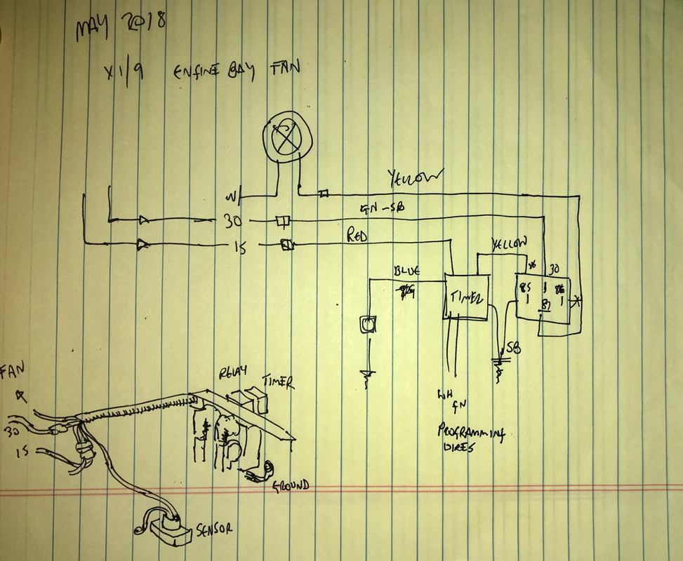
After I get back from Carlisle Import show. Taking the Volvo this year.
Can’t see taking on the electric water pump mod. Too many variables and margin for error. I’d have to buy two pumps in case one failed, since they are all the way around the world from me. Kinda like my custom brake setup - have to keep the custom pad$$$$ and rotor$$$ in stock. My setup works, barring the aforementioned idle after highway run temp concern. I’ll see in the coming weeks if my setup does the trick. If it ever stops raining, that is.
Will be wired thus:
After I get back from Carlisle Import show. Taking the Volvo this year.
Can’t see taking on the electric water pump mod. Too many variables and margin for error. I’d have to buy two pumps in case one failed, since they are all the way around the world from me. Kinda like my custom brake setup - have to keep the custom pad$$$$ and rotor$$$ in stock. My setup works, barring the aforementioned idle after highway run temp concern. I’ll see in the coming weeks if my setup does the trick. If it ever stops raining, that is.
Last edited:
dcioccarelli
Dominic Cioccarelli
So, a bit late to the party here but a very good thread.
I fully concur. If you drive for extended periods at high speed (rev range > 4.5K) and then come to a sudden halt (like before the bloody Gotthard tunnel in summer behind a line of Dutch caravans) then I can guarantee that pretty much any X1/9 will suffer from a swing into the danger zone. This can be averted by having a good radiator and good fans and bringing the revs up to around 1.5K. This would strongly suggest that the issue is that the flow rate delivered by the pump is insufficient at idle for these specific conditions.
I don't believe that a secondary pump is a solution (unless it was combined with electrically operated unidirectional valves). Most (if not all) secondary pumps (including those made by Davies Craig who also produce primary electric pumps) are for very specific auxiliary circuits such as heating or LPG systems. I have yet to see a secondary pump that acts in tandem with a primary pump on the primary cooling circuit (but I'd be happy to stand corrected).
You can simulate fluid flow with an alalogous electrical circuit, as per:
http://hyperphysics.phy-astr.gsu.edu/hbase/electric/watcir.html#c1
What you end up with is something like this (in LTspice) where we have a more restrictive branch with a smaller pump:

What you realise is that increasing the pump size (battery voltage) doesn't have a huge impact on the total flow (current through R3).
Cheers,
Dom.
I think the issue is primarily the idle speed driven capacity of the water pump. At low engine speed the pump is not moving enough coolant to move the heat reservoir in the engine mass which has been running at 4K for miles to the radiator. The radiator and the fan(s) can keep the temp down and you will see that if you rev the engine at 2k while stopped which ensures enough flow through the radiator of the hot coolant out of the engine and the cooled coolant back to the engine.
I fully concur. If you drive for extended periods at high speed (rev range > 4.5K) and then come to a sudden halt (like before the bloody Gotthard tunnel in summer behind a line of Dutch caravans) then I can guarantee that pretty much any X1/9 will suffer from a swing into the danger zone. This can be averted by having a good radiator and good fans and bringing the revs up to around 1.5K. This would strongly suggest that the issue is that the flow rate delivered by the pump is insufficient at idle for these specific conditions.
A secondary pump which could be tipped to run when at idle only by the TPS controlling a relay would ameliorate this tendency. Bob Brown installed his for just their reason oh so long ago in the Which brings us to why cars are moving to electric coolant pumps in general so that cooling can be kept in a tightly controlled range.
I don't believe that a secondary pump is a solution (unless it was combined with electrically operated unidirectional valves). Most (if not all) secondary pumps (including those made by Davies Craig who also produce primary electric pumps) are for very specific auxiliary circuits such as heating or LPG systems. I have yet to see a secondary pump that acts in tandem with a primary pump on the primary cooling circuit (but I'd be happy to stand corrected).
You can simulate fluid flow with an alalogous electrical circuit, as per:
http://hyperphysics.phy-astr.gsu.edu/hbase/electric/watcir.html#c1
What you end up with is something like this (in LTspice) where we have a more restrictive branch with a smaller pump:
What you realise is that increasing the pump size (battery voltage) doesn't have a huge impact on the total flow (current through R3).
Cheers,
Dom.
just FYI: Turbo Audi's and both turbo and VR6 VW's from at least 1991 had a aux water pump in their cooling system. Might be worth looking into.
Dr.Jeff
True Classic
Dom's comments parallel what I have been saying. For a two-pump set-up, the entire system needs to be engineered as a specific design that works that way.I don't believe that a secondary pump is a solution (unless it was combined with electrically operated unidirectional valves). Most (if not all) secondary pumps (including those made by Davies Craig who also produce primary electric pumps) are for very specific auxiliary circuits such as heating or LPG systems. I have yet to see a secondary pump that acts in tandem with a primary pump on the primary cooling circuit (but I'd be happy to stand corrected).
Which is exactly what you will find here.....
Turbo Audi's and both turbo and VR6 VW's from at least 1991 had a aux water pump in their cooling system
lookforjoe
True Classic
Pretty sure those setups are using the aux pump to circulate the turbo water jacket cooling, so essentially an auxillary circuit only.
Dr.Jeff
True Classic
True the VAG vehicles' aux pump is primarily to aid the turbo, but they are part of the main cooling system. And the system was designed to allow for the secondary pump to function in conjunction with the primary/main pump. That was the point I was trying to make, having the entire system engineered to work with two pumps so they don't defeat one another. This would be very difficult to do correctly on an existing cooling system not designed around it.
Tedd
Daily Driver
I do not have much experience with the X cooling system yet but I do have a vanagon with a Subaru engine I installed. It is a common swap and there are many kits. Might find some solutions there but I do not remember seeing anyone use a secondary pump. I have a cooling issue if I start it and leave it idle. The system will not circulate. I was thinking about adding an electric pump myself. One thing I find is the flow will go through the heater preferential to the radiator. I have to modulate the heater control. Otherwise the Subaru is a real treat!
lookforjoe
True Classic
If you ever want unload that pipe for the auxiliary water pump let me know.
I found the pipe
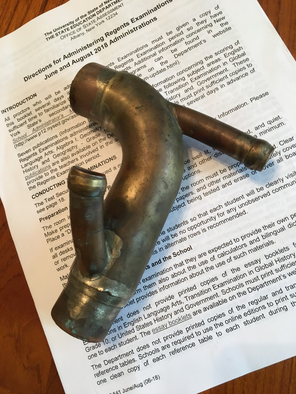
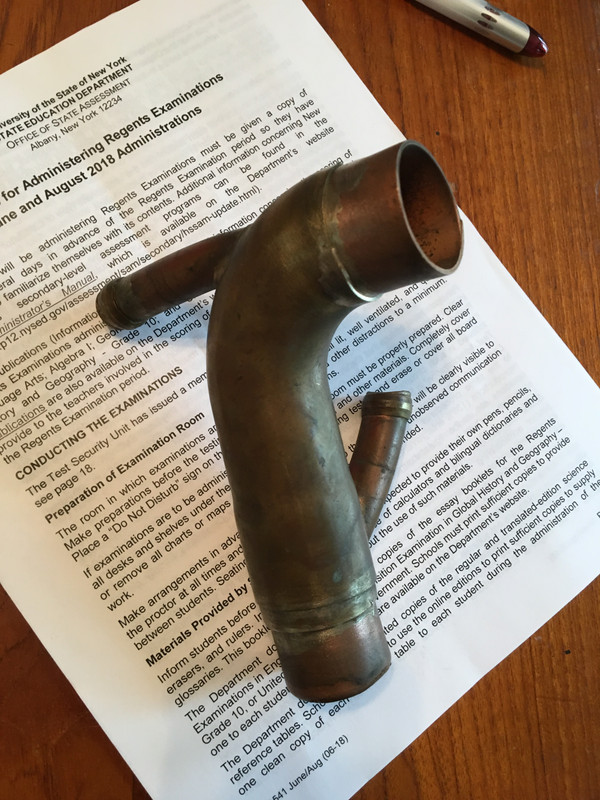
PM me & I'll send it to you.
lookforjoe
True Classic
Hello Jeff
As Karl surmised, they are compression “olives”. I think everything was silver-soldered, which would be my SOP for something like this, but it’s been years so I’m not 100% on that.