What did you do to your X1/9 today ?

Started doing a bit of work on the Scorpion. I'm fabricating a removable steel roof panel that tightly follows the lines of the car. I have never been wild about how the 037 roof panels sit so proud and high. I know they're a practical concession to wearing a racing helmet but I doubt I will be wearing a helmet in this car. If I ever find myself in that situation, I will bite the bullet (stylistically) when it happens.

View attachment 13310

I will put together a video showing my progress shortly. I've been beset by all manner of distracting side projects.
Ah yes, the distracting side projects. I sometimes think that my X is the distracting side project as my list of high priority things that need to get done grows.

A steel roof panel sounds ambitious but I'm sure with your skills it should come out great.

That trans tail lurking under the back of the Scorpion looks real bad-ass, and gives the impression that something special is going on inside. I suppose if this was an agricultural area you could add a PTO on the back to run farm equipment. Or, how about a propeller? You would not have to worry about tailgaters in that case although I don't think there will be many cars that could keep up with this beast.

I'll be looking forward to your next clip.
 
Sweet! It'd be twice as cool if you made two of them! I'll likely benefit from the extra room provided by the double bubble top, but I'm not really interested in having a removable one. I think the "coupes" were the coolest option for the Montecarlo, cleaner lines and less maintenance. Please-please keep going and post your progress on the x1/20 page!
 
Fixed my Broken Glove Box Lid hinge

Ground off and filed flat the remnants of the old broken plastic hinge hole, (left side, of course) after marking where everything had to line up.
Fashioned a bracket out of some unknown original bracket I found laying in a junk drawer.
Trimmed off the unnecessary bits, drilled and tapped all the holes in all the right places, and voilà, Bob's your Uncle!
Had to modify my plan, as the tape the factory used on the reverse side of the leather covered outer panel, obscured where the edge of the metal liner ended. The drill bit for these 2 holes just slid right off the edge, and I wasn't able to drill and tap those holes (like the other 2). So, I improvised and used 2 sheetmetal screws that were wide enough and stubby enough to get some bite, but not protrude far enough into the sheetmetal to damage the leather wrap. Not the most elegant solution I've ever created, but it's sturdy and after I paint it brown to match the rest of the plastic, no one will be the wiser. I also made an "L" shaped shim from a piece of scrap HVAC duct, that sits between the hinge bushing and the bracket. I folded over a 1/8" wide lip to double it up, and snipped off enough material on the vertical side to allow the bushing to pass through the hole. When everything is assembled and tightened up, the bushing will hold the shim in place. The doubled up lip that sits "under the bushing" takes up the space between the squared off bottom of the bushing and the bracket, filling the free space and preventing the bushing from spinning.

I saw the hinge repair piece that Vick's sells for 30.00, but after researching what was involved with that, I thought I could do a better job, myself.
Hope this helps anyone else who wants to attempt this.
Glove Box Bracket 1.jpg
Glove Box Bracket 2.jpg
Glove Box Bracket 3.jpg


Tom, that looks great. Very cleanly done.
By chance can you provide suggested measurements where all four screws would catch the metal plate behind (without slipping off)? If that's possible to do.
Not sure I completely followed the "shim" description. It might be more obvious if I had mine in front of me while reviewing what you did. But can you possibly add any more detail?
I need to do this on two lids, so appreciate all the input you can offer. Thanks.
 
Glove box lid (right side) This is a mirror image of the left side (before it broke) Note the vertical "wings" that would prevent the square backed bushing nut from turning. Also note the raised "pad area" that's thicker than the rest of the plastic insert. This pad is 2" x 1-1/2"
Glove Box Lid right side.jpg


Bracket mounted by itself on left side pad. (Note: the hole on the bottom side of the bracket was "conveniently" already on the original part I made this from). I was initially going to duplicate the original assembly by machining it out of a billet of aluminum.
But a simple bracket was far easier to cobble together and as long as all the important parts line up and match the original hard points, it should work just fine and last for the life of the car. What I discovered is the outer shell (that has the leather/vinyl wrap) is actually made of 2 pieces of sheet metal with some mystery material sandwiched between them. The metal side that backs up to the plastic insert is sized only to match the O.D. pattern of the factory tapped holes for the "Three Hundred and Forty Two" tiny little phillips head machine screws used to mount these two skins together. The original design exerts a great deal of force on the actuator arm that's connected to the bushing nut. Any fix would require a more robust hinge point to handle the stress placed on the actuator arm. Also (because of where it's being mounted on the inside of the lid) it requires a "surface mount" of some type, made even more difficult by the fact that you have a very thin substrate to attach to. So the bracket material needs to be strong enough to handle the stress, and because of the surface mount...I wanted to spread the bracket base (and mounting points) as far away from the stress point as possible, to spread the load of the tension on the actuator arm as evenly across that thicker "pad" as possible. Looking everything over before I began and not knowing before I started that there were actually (2) Two pieces of sheetmetal that made up the outer shell, I located and drilled the mounting holes in my bracket, "before" I drilled the metal insert to tap the (4) Four new receiving holes. Had I started drilling the metal insert on the outer side first, I would have realized that I was off the top piece of sheetmetal and perhaps would have started again. Since I had already drilled the 4 pilot holes to tap...(2 of which were OK, 2 of which were not) I had no choice but to try and find short, fat, and pointy sheetmetal screws to use to attach the bracket base along the outer holes. These 2 screws grabbed enough of the mystery material and the bottom piece of sheetmetal to hold tight. And I sized the screws so that no matter what, they weren't going to pierce the outer leather/vinyl wrap. The bottom portion of the bracket is
1-1/2" x 1-1/2", the bushing nut hole diameter is 7/16". The "simple solution" is to move the two mounting holes in the bracket further "inboard" to try and catch enough of the top layer sheetmetal to get a proper hole and tap. The problem is that this outer side of the the assembly is where the greatest load is (based on how the actuator arm twists to open the lid), and I'm not sure that locating the holes closer to the stress point (bushing nut) wouldn't negate the fact that you have a more secure connection with a proper drilled and tapped machine screw, vs a sheetmetal screw placed further out, like I did. To be honest, if I had to do it all over again, I would have just drilled tiny pilot holes and used sheet metal screws on all four holes. Whatever you decide to do... don't forget to allow for the thickness of your bracket base material when you're drilling you hole bushing nut hole. The final height and placement of that hole has to match the one on the right side, so the top of your glove box lands at the correct height and matches the rest of the dashboard when closed.
bracket in place on left side pad.jpg


Shim Close Up
shim close up.jpg

Shim in place
Shim in place.jpg

Bushing nut in place
Hinge Bushing nut in place.jpg
 
It's not what I've done to one of my X's today, but what I'm about to do!

With instructions in hand from Steve H., our resident transmission meister, I'm about to remove the transmission from my '85 Bertone X, so that I can ship it to Steve before summer is over, and his new work plans begin. With a little luck, I'll do the same with my '82 Fiat X soon, too. As mentioned elsewhere on XWeb, I wanted to announce the earnest start of this project just in case you don't see me writing for a while -- which just means I should have stuck to computers. ;) Wish me luck!
 
Excellent Tom, I can easily see it now. Thank you very much. ;)
Installed the glove box lid today, and had to make a couple of changes.
1. The bracket was rubbing on the edge of the glove box "tub" insert. I trimmed a little off the outer radius (where the bushing nut passes through) and removed some of the material off the top side creating a narrower angle from the base. It now rotates on the hinge without any interference.
2. The original plastic "loop" that held the bushing nut was approx. twice as wide as the thickness of the stock I used to make my bracket. After installing it I noticed some side to side slop that allowed the actuator arm to twist "slightly" thereby causing the bushing nut to move around. It worked fine, but I knew it was a matter of time before the bushing nut would start making the bracket hole "out of round". I ground a flat on one side of 1/8" thick washer (to drop the washer hole down to match the height of the bracket hole) and created a spacer. Of course I dropped the little nylon washer, the actuator arm, and the bolt and metal washer that holds everything together (each) at least 3 times while trying to put this together for the second time! But I finally got it and it works perfectly. I also trimmed and re-bent one end of the spring to make it shorter, so it pulls the lid open further than it did before. This took "way longer" than I had planned, but it was very satisfying to finally get it to work.

This is where I did most of the trimming.
bracket mod.jpg


and this is the result
Glove Closed.jpg

Glove Open.jpg
 
Tom, nice work on your glove box lid. :) You should consider putting together a Workshop Forum post covering your project. It will be easier for others to find in the future.
 
Tom, nice work on your glove box lid. :) You should consider putting together a Workshop Forum post covering your project. It will be easier for others to find in the future.
Thanks Jim. I'd be happy to do that, if you would be kind enough to explain the best/easiest way to migrate this over. Is it simply a mater of copying and pasting?
 
Tom, indeed a job well done. Thanks for the updates. Your interior looks to be in amazing condition, including a crack free dash. Thanks again for sharing.

I think you could probably "cut/paste" the posts into the other section of the forum(?), but I'll let someone more qualified answer. Perhaps just put all of your entries into one post and then you could do a little editing if you wish. That would be great, this "what I did today" thread is one of those that goes on forever and makes it very hard to refer back to as Jim said.
 
Today -- I mean yesterday -- I successfully removed the transmission from my '85 Bertone X, and then shipped it to Steve H. via FedEx Ground. It took me a bit longer than I expected, with a few interruptions for less important things, such as work, but with my brothers' help, and some additional tools borrowed from one of our nephews, the deed is done. It'll be interesting to see how easily things go back together again later. I want to thank the XWeb community for emboldening me to try -- the initial part of the process is now a success!

I just finished taking a nap, and even though it's past midnight I'll be working on repairing a laptop that a client of mine will be picking up tomorrow -- I mean today -- shortly before noon. I usually don't work after 9 pm, let alone after midnight, but I also don't usually remove a transmission from one of my sports cars, to get it refurbished by a bonafide transmission meister, so "unusual" is not bad in this case. :D
 
Last edited:
Installation is not any harder than removal, once you get the input shaft lined up and the trans seated against the engine.
 
Installation is not any harder than removal, once you get the input shaft lined up and the trans seated against the engine.
... in theory.

You will need to use a centering tool to align the clutch. To raise the transmission, I'm using a floor jack so I don't have to lift the weight while trying to align the studs into the holes and the shaft into the clutch.
 
I bought a small scissors lift used for motorcycles to put on top of a moving dolly to lift the transmission and allow me to move it sideways into place. As I do everything pretty much by myself I tent to over invest in tools to assist me in getting the job done.

I also bought some of those trailer scissor jacks (rated to 7500lbs each) to lift it 24” up and two sets of 6ton jack stands to hold the X up in the air higher.

I also have a beam to hold the engine up from above that sits on the strut towers.

I know, overkill.
 
Special K, I can relate. I'm the same, work alone and therefore have the very same sorts of equipment. At times it would be less expensive to hire someone rather than buying more tools/equipment. But I never stop to think about that. To get the rear of the X high enough to clear an engine or trans on a jack (removal or installation) I use the engine hoist ("cherry picker"), then the extra tall jack stands under the chassis. But I've been looking at a jack that has an extra long reach (that's all I need, another jack). Always a trade-off though; to get a higher reach you usually have to lose some ground clearance when it is in the "down" position...sucks on very lower vehicles.
 
I also have a beam to hold the engine up from above that sits on the strut towers.

That's what I use for transmission removal/installation in combination with a pair of ratchet straps.

It's great because one piece of equipment simultaneously holds the engine and provides a stable platform to suspend the transmission from.

The pair of ratchet straps get wrapped around the beam and the transmission and then the ratcheting mechanism allows me to raise/lower and pitch the transmission easily while holding it in place without having to deal with a cumbersome jack from underneath or the impossible task (for me) of having to lift it into place manually with no assistance.

To install, I get it as close as possible with the beam and ratchet straps and then crawl under the car and bench press it the rest of the way. The great part about doing it this way, is if it slips from my grip or I get tired, the straps will catch it and since it's already suspended I don't have to wear myself out in the process.
 
I could see making something of a gantry mechanism that attaches to the support beam. Then the trans (or engine) could be maneuvered easily Into position while it is suspended from the beam.
 
Today -- I mean yesterday -- I successfully removed the transmission from my '85 Bertone X, and then shipped it to Steve H. via FedEx Ground. It took me a bit longer than I expected, with a few interruptions for less important things, such as work, but with my brothers' help, and some additional tools borrowed from one of our nephews, the deed is done. It'll be interesting to see how easily things go back together again later. I want to thank the XWeb community for emboldening me to try -- the initial part of the process is now a success!

I just finished taking a nap, and even though it's past midnight I'll be working on repairing a laptop that a client of mine will be picking up tomorrow -- I mean today -- shortly before noon. I usually don't work after 9 pm, let alone after midnight, but I also don't usually remove a transmission from one of my sports cars, to get it refurbished by a bonafide transmission meister, so "unusual" is not bad in this case. :D

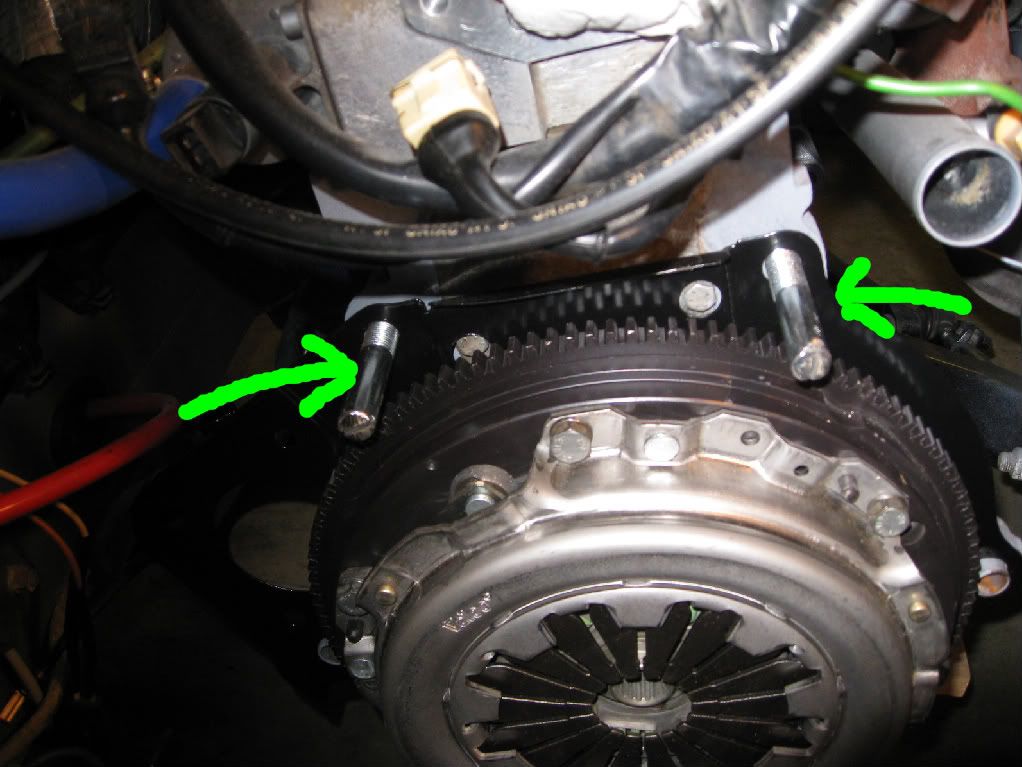
Installation is a snap when you make a pair of locating rods/studs like so out of long capscrews (cut off heads, and then cut a slot in the end):

IMG_1124-1.jpg


One tip if using the above locating studs: leave the right side (NA passenger side) CV stub axle/flange off the trans until after installation. If you don't, the CV joint flange will just foul the ear and prevent the bell housing from mating with the block.
1300 head studs will work too :)
 
Back
Top