Wiring backup cooling fan switch from ECU

fiatmonkey

Tim Hoover
Hi,

NOTE: This is for the k20a2 swap'd X...


The Hondata ECU has an option where you can have it trigger a low amperage negative (-) signal that could be used to trip the radiator fan. I can set the trip temp to whatever I want, so I want to use it as a "back-up" option when the ECU shows the engine is hotter than the radiator switch detects it.

My plan is to change the low amperage signal to a solid ground by using a relay like this:
How-to-guides_-_Relay_applications.png


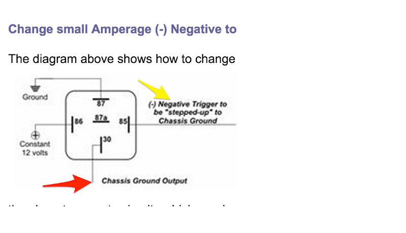
The yellow arrow is the ECU signal, the red is the solid ground I have when the signal is detected.

My plan is to take that solid ground and feed it to the stock sending unit wiring and switch-bypass it. I *think* I could just take the ground from the relay (red arrow) and pig tale splice it to both black and red wires that connect to radiator? I am planning this properly?

Thanks,
Tim
 
Last edited:
I am over thinking this a little. I suppose what I should do is just continue the grounded(or ungrounded) signal from the radiator switch. Just need to figure out which one that would be. My wiring to the radiator temp sensor is custom and I didn't keep the wiring color consistent with what was stock. I think it *was* red and black...
 
Tim... I hope I understood what you were/are saying...

But first off... in your drawing below you have wired it in what I think is a non-standard way.

Pin 30 is usually the SOURCE, be it voltage or ground.

Pin 87 is the Normally Open (NO) HIGH AMP (Current) OUTPUT to the device (Fans, in this case or Fan Relay) when THIS relay OPERATES.

Pin 87a
is the the Normally Closed (NC) terminal (when used) that will supply the SOURCE (be it voltage or ground) when THIS relay is AT REST.

Pins 85 and 86 can be interchanged and I don't recall the protocol,
but in this case you have Voltage standing on one terminal of THIS relay's COIL, and are applying "Triggers" from the ECU or a Manual Override Switch to operate this relay.

(Your drawing here...)

How-to-guides_-_Relay_applications.png


Considering all I said and understand you to say, I suggest you wire this relay and this circuit in this manner:

Click on to make larger...


7qDkQCAQCgUAgEAgEdhSBIFg72rHRrEAgEAgEAoFAIBBYHwJBsNaHfdQcCAQCgUAgEAgEAjuKQBCsHe3YaFYgEAgEAoFAIBAIrA+BIFjrwz5qDgQCgUAgEAgEAoEdRSAI1o52bDQrEAgEAoFAIBAIBNaHQBCs9WEfNQcCgUAgEAgEAoHAjiIQBGtHOzaaFQgEAoFAIBAIBALrQyAI1vqwj5oDgUAgEAgEAoFAYEcR+P8BDsMw35OPZCoAAAAASUVORK5CYII=

Hope this helps...
 
fan relay

everybody seems to be overthinking this relay stuff.
power to the relay...ground ...the switch you use to send a signal to the relay...is for energizing the relay and completing the circuit for what ever you want to run. some of the relays have an extra terminal, so as the relay becomes energized, it switches power in a different direction.
jeeze papa....
I figure you were around before they had these and you and were responsible for throwing the "switch" by hand
and they all thought that the spare tire straps way back then were for spare tires.
I have seen your initials carved in a few model A's....


HA BACK ATCHA:nana:
mikemo
 
Thanks Tony. You just reversed the poles on me :) They do the same thing. I don't think there is a standard either, but I could be wrong.

That said, you confirmed (generally) what I am going to do, and added a manual switch (which I am not going to add).

Regards,
Tim
 
HAHAHA... ya know after I drew all that I came to...

the same conclusion... but felt what the hell... I'll post it anyway. It appeared CLEARER, at least to me! HA!

I do contend that the "odd" terminal designation 30 is indeed the SOURCE terminal. Terms 87 and 87a kinda confirm it as they are the output of whether you want a NO or NC function. Terms 85 and 86 probably don't make any difference regardless of voltage and type.

Many times you will find a jumper between terminal 30 and 85 so that a - or ground will operate the relay via term 86 and supply voltage out terminal 87.

ANYWAY... I gotta go and I am glad it worked!!!
 
Back
Top