StaticTiming: Difference between revisions
No edit summary |
No edit summary |
||
| (7 intermediate revisions by one other user not shown) | |||
| Line 4: | Line 4: | ||
Timing Belt Replacement, Cam Timing and Static Ignition Timing. | Timing Belt Replacement, Cam Timing and Static Ignition Timing. | ||
Photos courtesy of Don Doan. | Photos courtesy of Don Doan. | ||
Text courtesy of Keiran. | |||
* [[Media:Fiat_X19_1500_Engine_-_Guide_to_Timing_Belt_Replacement_Cam_and_Ignition_Timing.pdf|PDF version of this guide]] | |||
=== Introduction === | === Introduction === | ||
| Line 71: | Line 75: | ||
Photo 1 | Photo 1 | ||
[[File:EngineStaticTiming. | [[File:EngineStaticTiming.JPG]] | ||
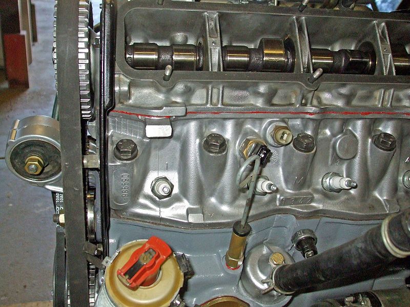
This is what the 1500 cc engine looks like removed from the car. First, the yellow | This is what the 1500 cc engine looks like removed from the car. First, the yellow | ||
| Line 79: | Line 83: | ||
Photo 2 | Photo 2 | ||
[[File: | [[File:DSCF2296_edited.jpg|800px]] | ||
1500cc engine crank pulley TDC alignment. | 1500cc engine crank pulley TDC alignment. | ||
| Line 85: | Line 89: | ||
Photo 3 | Photo 3 | ||
[[File:DSCF2273_edited.jpg]] | [[File:DSCF2273_edited.jpg|800px]] | ||
With the belt cover removed, the cam pulley, belt tensioner pulley, and auxiliary | With the belt cover removed, the cam pulley, belt tensioner pulley, and auxiliary | ||
| Line 91: | Line 95: | ||
Photo 4 | Photo 4 | ||
[[File:DSCF2274_edited.jpg|800px]] | |||
Using a 17mm socket, loosen the tensioner pulley nut. The tensioner pulley is | Using a 17mm socket, loosen the tensioner pulley nut. The tensioner pulley is | ||
| Line 99: | Line 105: | ||
Photo 5 | Photo 5 | ||
[[File:DSCF2275_edited.jpg|800px]] | |||
You can use a large slotted screwdriver to press against the tensioner pulley | You can use a large slotted screwdriver to press against the tensioner pulley | ||
| Line 104: | Line 112: | ||
Photo 6 | Photo 6 | ||
[[File:DSCF2289_edited.jpg|800px]] | |||
This shows the flange at the base of the tensioner pulley bracket. You need to | This shows the flange at the base of the tensioner pulley bracket. You need to | ||
| Line 110: | Line 120: | ||
Photo 7 | Photo 7 | ||
[[File:DSCF2276_edited.jpg|800px]] | |||
With the tension on the belt released, tighten the tensioner pulley nut to keep the | With the tension on the belt released, tighten the tensioner pulley nut to keep the | ||
| Line 115: | Line 127: | ||
Photo 8 | Photo 8 | ||
[[File:DSCF2277_edited.jpg|800px]] | |||
The timing belt can now be pulled off the cam pulley. | The timing belt can now be pulled off the cam pulley. | ||
Photo 9 | Photo 9 | ||
[[File:DSCF2278_edited.jpg|800px]] | |||
Use a 38mm socket to loosen the crankshaft nut. The timing belt is situated | Use a 38mm socket to loosen the crankshaft nut. The timing belt is situated | ||
| Line 124: | Line 140: | ||
Photo 10 | Photo 10 | ||
[[File:DSCF2279_edited.jpg|800px]] | |||
The crankshaft pulley has been slipped off the crankshaft, exposing the timing | The crankshaft pulley has been slipped off the crankshaft, exposing the timing | ||
| Line 130: | Line 148: | ||
Photo 11 | Photo 11 | ||
[[File:DSCF2280_edited.jpg|800px]] | |||
Remove the timing belt and discard. | Remove the timing belt and discard. | ||
Photo 12 | Photo 12 | ||
[[File:DSCF2281_edited.jpg|800px]] | |||
Fit a new timing belt to the sprocket, replace the crank pulley and tighten the | Fit a new timing belt to the sprocket, replace the crank pulley and tighten the | ||
| Line 139: | Line 161: | ||
Photo 13 | Photo 13 | ||
[[File:DSCF2293_edited.jpg|800px]] | |||
If the crank pulley is at TDC, the dimple on the flywheel (seen through the | If the crank pulley is at TDC, the dimple on the flywheel (seen through the | ||
| Line 148: | Line 172: | ||
Photo 14 | Photo 14 | ||
[[File:DSCF2295_edited.jpg|800px]] | |||
Ensure the cam pulley is aligned with the pointer on the belt guard. | Ensure the cam pulley is aligned with the pointer on the belt guard. | ||
| Line 154: | Line 180: | ||
Photo 15 | Photo 15 | ||
[[File:DSCF2273_edited.jpg|800px]] | |||
With the cam and crank pulleys aligned with their TDC marks, slip the belt back | With the cam and crank pulleys aligned with their TDC marks, slip the belt back | ||
| Line 162: | Line 190: | ||
Photo 16 | Photo 16 | ||
[[File:DSCF2296_edited.jpg|800px]] | |||
Use the 38mm socket to rotate the crankshaft completely around two times. | Use the 38mm socket to rotate the crankshaft completely around two times. | ||
| Line 169: | Line 199: | ||
correct and the timing belt has been correctly replaced. Lastly, replace the | correct and the timing belt has been correctly replaced. Lastly, replace the | ||
yellow timing belt cover. | yellow timing belt cover. | ||
Setting the Static Ignition Timing | |||
First, it is advisable to ensure that the timing of the crankshaft and cam pulleys line up with their respective TDC marks as shown in photos 12, 13 & | === Setting the Static Ignition Timing === | ||
14 above. If these are correct, go through the following photos to set the static ignition timing. | |||
First, it is advisable to ensure that the timing of the crankshaft and cam pulleys line up with their respective TDC marks as shown in photos 12, 13 & 14 above. If these are correct, go through the following photos to set the static ignition timing. | |||
Photo 17 | Photo 17 | ||
[[File:DSCF2297_edited.jpg|800px]] | |||
Use a 38mm socket to rotate the crankshaft clockwise until the mark on the | Use a 38mm socket to rotate the crankshaft clockwise until the mark on the | ||
| Line 182: | Line 215: | ||
Photo 18 | Photo 18 | ||
[[File:DSCF2299_edited.jpg|800px]] | |||
If the crankshaft has been rotated correctly and stopped on the 10º BTDC mark, | If the crankshaft has been rotated correctly and stopped on the 10º BTDC mark, | ||
| Line 188: | Line 223: | ||
Photo 19 | Photo 19 | ||
[[File:DSCF2290_edited.jpg|800px]] | |||
With the crankshaft pulley set to 10º BTDC, remove the distributor cap to expose | With the crankshaft pulley set to 10º BTDC, remove the distributor cap to expose | ||
| Line 194: | Line 231: | ||
Photo 20 | Photo 20 | ||
[[File:DSCF2284_edited.jpg|800px]] | |||
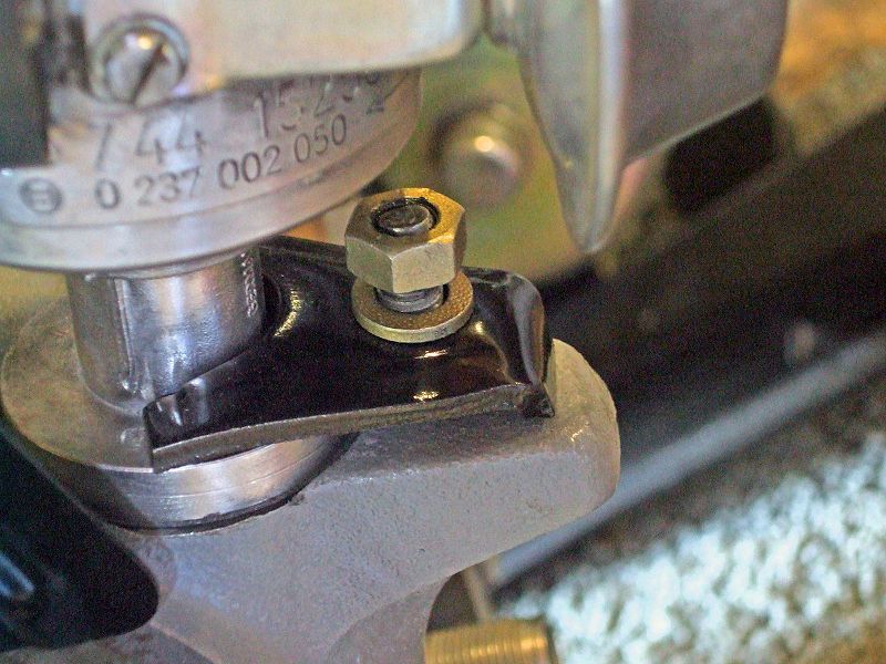
To set the required distributor position, undo the 13mm nut at the base of the | To set the required distributor position, undo the 13mm nut at the base of the | ||
| Line 199: | Line 238: | ||
Photo 21 | Photo 21 | ||
[[File:DSCF2292_edited.jpg|800px]] | |||
Remove the distributor from the engine and turn the rotor until it points toward | Remove the distributor from the engine and turn the rotor until it points toward | ||
| Line 212: | Line 253: | ||
With everything else being correct, the engine should now start and you can then use a timing light to set the ignition timing exactly. | With everything else being correct, the engine should now start and you can then use a timing light to set the ignition timing exactly. | ||
Dan's write up; | |||
There are two types of timing: Cam/valve/engine and ignition. | |||
People variously use the terms cam, valve, and engine timing to describe the same concept, which appropriately enough is getting the moving parts of the engine (cam, valves, distributor and engine crankshaft and therefore pistons) to all sync up the way they need to. | |||
On an X1/9, getting the above synched up involves positioning the cam and crank timing marks, BUT, when they are positioned properly, cyl #4 and NOT cyl #1 happens to be on the compression stroke. | |||
But, when you get the cam and crank timing set, because the dist is run from the aux shaft whose drive sprocket has no specific positional relationship to the cam and crank sprockets, the distributor is synced to the cam and crank in a separate step on an X1/9. | |||
One more thing about that....when the cam and crank timing marks are set, that does not necessarily mean that the timing pointers on the pulley end of the engine are perfectly set. The are sheet metal, and the holes by which the pointers are mounted to studs are bigger than the studs, and therefore can be off as much as 5-10 degrees. The most accurate pointers are the hash marks on the bell housing that line up with the dot/dimple on the flywheel. These are visible thru the "window" at the 12 o'clock position on the bell housing. | |||
The other type of timing, ignition, on an X1/9 is just like on most other cars, getting the spark delivered to the cylinder at the right time as shown to you by a timing light. While on the X (and most 4 cylinder engines) you can set ignition timing from the #1 or #4 cylinder, 99.9% of the time people will set ignition timing with the timing light connected to #1 cyl. | |||
Follow these steps (apply only to 1500 engines): | |||
1. Park on a hard level surface, parking brake off, chock a wheel for safety. Trans in 4th gear. | |||
2. Using a floor jack positioned under the right rear suspension, raise the right rear wheel just enough to clear the ground/floor | |||
4. Remove spare tire and distributor access panel. | |||
5. Remove the black plastic cap from the timing window at the top of the trans bell housing and from the top of the yellow plastic cam belt cover | |||
6. Grasp the right rear tire (or put a lug wrench on a lug nut) and slowly turn the wheel clockwise until you see the timing notch/dimple on the cam sprocket line up with the pointer. When these are lined up, you are at TDC of Cyl #4 on the compression stroke. Yes, this is what you want for the moment. | |||
****WARNING! DO NOT rotate the wheel counterclockwise for ANY reason....this would rotate the engine backwards, possibly causing the timing belt to jump teeth. If you over-rotate the wheel and miss a mark, no problem, just keep turning and get it on the next go-around.***** | |||
7. Now, go around the other side and check the hash marks on the bell housing and the dot on the flywheel. The dot should be lined up with the Zero hash mark. | |||
NOTE: If the dot does not line up with the Zero has mark, recheck your work. If you are sure the cam hash mark or dot is lined up with the cam cover backing plate pointer, there are explanations: the flywheel may have been install 180 degrees out; the cam belt may have jumped teeth, or the cam sprocket has some sore of mounting issue. | |||
8. Take this opportunity to highlight the hash marks, dots, pointers and such with white or yellow paint and a fine brush. Don't bother with the pointers at the pulley end of the engine, they are IMHO pretty much useless (too hard to see at a direct angle when using a timing light and too hard to get to, to adjust). If you insist upon using the pulley end pointers, now is the time to make sure they are adjusted accurately and marked with paint. | |||
9. To recap, cam sprocket notch/dimple lined up with cam cover backing plate pointer = #4 TDC on compression stroke. Verify with dot and hash mark on trans bell housing. If all good, reach into the car and apply the handbrake, locking it down. | |||
Assuming all of the above is good, proceed to syncing the distributor. | |||
10. The position of the dist body on its engine block mounting pad is not located critically like the cam and crank are, and that explains why there are no hash marks on the dist or the mounting pad to line up. Practically speaking, the best position for the distributor body is with the vac capsule on the right (pass) side of the car, and assuming you have the dist cap with the side-loading wires, the wire terminals pointing to the left rear shock tower. This allows the stock length wires to fit nicely and allows enough room for the vac capsule to swing without hitting anything (like the side of the cam belt cover and backing plate) as you rotate the distributor to adjust ignition timing. | |||
11. If your dist is not positioned as above, remove the 13mm hold down nut and hold down, raise the dist body away from its engine mounting pad by about 2", rotate the dist body as needed, then lower it back down. The inside end of the dist shaft is splined to the aux shaft, so you may have to rotate the dist a little bit one way or the other to get it to sit back down into its position. Again, the position of the dist body is not critical so don't sweat it....just get the vac capsule on the right and have the spark plug wire terminals point to the left rear shock tower. Don't reinstall the holddown just yet. | |||
12. Next, pop the cap off of the distributor body, flip it over, and examine its condition. The center button and the four metal contacts should be in good condition. The take a look at the rotor, make sure its center contact pad (that mates with the button on the cap) and the rotor tip are also in good condition. | |||
13. Looking at the design of the cap, trace the path of the #4 spark plug wire from its terminal on the exterior of the cap and find its internal contact along the inside top of the cap. Using a Sharpie marker or equivalent, place a vertical hash mark directly below this contact along the bottom edge of the cap, both inside and outside. Replace the cap onto the dist, making sure to line up the notch in the dist body rim with the corresponding bump along the bottom edge of the cap. Hold the cap in place securely, and then make a vertical mark on the exterior of the dist body just below the cap. Don't worry if you happen to jostle the dist body out of place a little while doing this; just so you get it back to where you had it in step 11. | |||
14. Now remove the cap from the dist body and set aside. What we want to see is the center of the tip of the rotor pointing directly at the vertical hashmark you made on the dist body. If it is, great, go on to the next step. If not, pull the dist body out of the block by about 2", hold with one hand, trying not to rotate the dist left or right, then with the other hand, rotate the rotor so that the center of the rotor's tip is pointing to your hashmark on the dist body, then with both hands maintain their positions, lower the dist body back into the block. If you accidentally rotated the dist body too much, pull it out of the block by about 2", reposition, and try again. If the dist body positioning is still good but when you lower the dist back into the block the rotor wants to rotate away from the hashmark, that's normal. As long as the hashmark lines up within the arc of the rotor tip contact, you are close enough to proceed to the next step. | |||
15. Without rotating the dist body, install the dist holddown , washers and nut, and tighten snugly but not completely. Replace the cap and clip the cap into place. | |||
16. Recheck that parking brake is applied, lower the right rear wheel from the jack, place trans in neutral. | |||
17. Now you are ready to check ignition timing with a timing light. Install the light according to manufacturer's instructions; if the timing light has a knob to adjust the light to the advance, make sure for now it is set to Zero. Technically you can set ignition timing from either the #1 or the #4 cylinder ignition wire/spark plug, but most people will use #1. | |||
18. Follow the factory shop manual instructions on preparing the car for checking and setting ignition timing. For example, on a fuel injected car, you should ensure that the car is warmed up, that the idle speed is around 900 RPM, and that the vac line to the vac advance capsule is removed from the vac advance capsule and plugged at the vac advance capsule end. Carb people should follow the carbed car procedure. Make a note of what your idle speed is before continuing. | |||
NOTE: For the following adjustment steps, a helper to turn the dist body saves a lot of hassle. | |||
19. From as direct an angle as possible given the confined area in which we have to work, point the timing light at the timing marks visible in the bell housing window (or the pointers on the pulley end of the engine). If you cannot see the dot on the flywheel or the hashmark on the crank pulley, then your setup is either way too advanced or way too retarded. Go around to the dist access panel, loosen the 13mm holddown nut, rotate the dist body about 1/2" in either direction, snug the nut, and have another look with the timing light. If you can now see the dot or hashmark, good. If not, back to the dist, loosen the nut, and this time rotate an inch in the opposite direction, tighten and check the light. If you still cannot see the dot/hashmark, repeat the adjusting process a 1/2" at a time until the timing marks come into view. | |||
NOTE: If you can see your timing marks but they seem to be "jumping" all over the place, try a different timing light. There will be some small degree of dot/hashmark movement visible under the light, but too much movement will prevent you from accurately adjusting timing. If you have tried several good-quality lights and still see excessive movement, then that could be an indicator of mechanical issues in the distributor, a loose cam belt, or problems within the ignition system. | |||
20. Once you have them in view, continue the process of rotating the dist body and checking the marks. The ignition timing spec is 10 degrees before for FI cars and IIRC, 5 degrees before for carbby cars. Once set to spec, don't forget to securely tighten the holddown nut. | |||
21. Be sure to replace any disconnected vacuum lines! | |||
22. If your ignition timing was way off, it could have affected your idle speed and/or idle quality....if it has changed significantly from what it was in step 18 before you started, follow the factory shop manual procedure to adjust. | |||
23. Before buttoning up the dist access panel and replacing the spare, take it for a test drive and observe for unusual sounds or behavior. Hopefully it runs better than ever! | |||
Latest revision as of 22:27, 12 November 2016
Static Engine Timing
Fiat X1/9 1500cc Engine
Timing Belt Replacement, Cam Timing and Static Ignition Timing.
Photos courtesy of Don Doan. Text courtesy of Keiran.
Introduction
This document outlines how to replace a timing belt on a Fiat X1/9 1500cc engine. It shows how to align the crankshaft pulley, flywheel and cam pulley for correct cam timing. Finally, it shows the approximate distributor position for static ignition timing.
The photos in this guide are of a 1500cc engine with fuel injection, electronic ignition and air conditioning. Differences to a 1300cc engine are mentioned where appropriate however please double check any differences are correct as my personal experience is only with a 1500cc engine.
Some other important points to note:
- The static ignition timing of a carbureted engine is 5º BTDC.
- The static ignition timing of a fuel-injected engine is 10º BTDC.
- Ignition timing is set relative to the position of number 4 cylinder – not number 1 cylinder as on
most other manufacturer’s engines.
- The Fiat X1/9 1500cc engine is a non-interference engine whereas the 1300cc engine is not. This
means that even if the cam timing is off, the pistons and valves will not collide (or “interfere” with one another) in a 1500cc engine. Thus, replacement of the timing belt at the recommended intervals is especially important for a 1300cc engine.
- For a 1500cc engine, with the crankshaft pulley at TDC, the cam pulley should align with the
pointer on the belt guard.
- For a 1300cc engine, with the crankshaft pulley at TDC, the cam pulley should align with the
pointer on the side engine mount.
- The most accurate TDC mark for the crankshaft pulley is a line cast into the front crank seal
housing. The reference pointer may be bent or may have been removed at some stage and installed slightly off.
- The flywheel is the next best indicator of crankshaft TDC but it too was removed at some stage, it
may have been refitted 180º out.
- The photos in this guide are of a clean engine with some parts and timing marks painted to make
them easier to see. This is not the case with a normal engine. Engine Components & Terminology
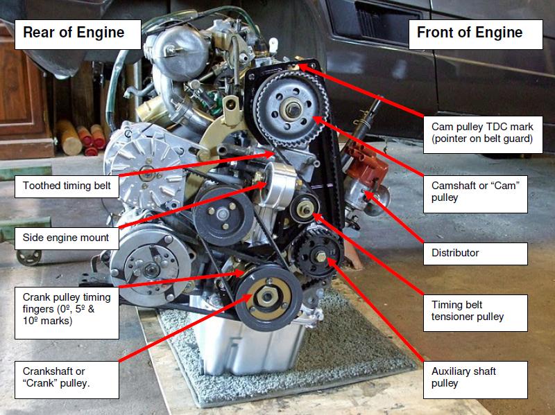
The following photo is used to identify important engine components that will be referred in this guide. Although the terms used may not be technically correct, hopefully this photo will help avoid confusion.
Crankshaft or “Crank” pulley. Camshaft or “Cam” pulley Toothed timing belt Auxiliary shaft pulley Timing belt tensioner pulley Side engine mount Crank pulley timing fingers (0º, 5º & 10º marks)
Rear of Engine Front of Engine Distributor Cam pulley TDC mark (pointer on belt guard)
Timing Belt Replacement Procedure
The following photos show how to replace the timing belt.
Before changing the timing belt, it is good practice to set the engine to TDC.
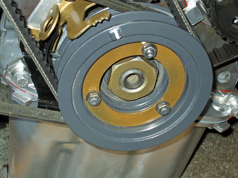
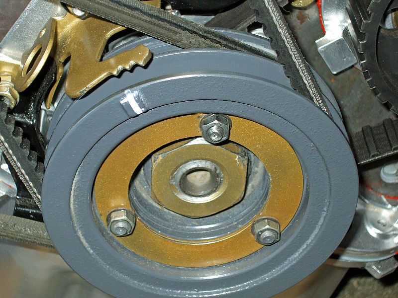
Do this by rotating the crankshaft pulley clockwise until the mark on the crank pulley is aligned with the right hand pointer on the timing finger (refer photo 2).
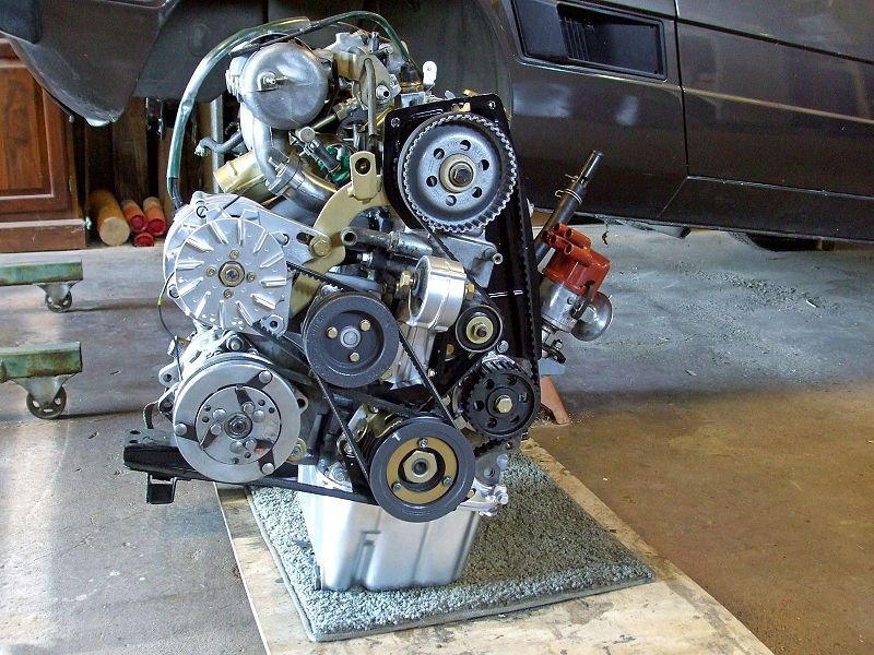
Photo 1
This is what the 1500 cc engine looks like removed from the car. First, the yellow plastic belt cover has to be removed by undoing four 10mm bolts – two at the top, one in the centre and one at the bottom.
Photo 2
1500cc engine crank pulley TDC alignment.
Photo 3
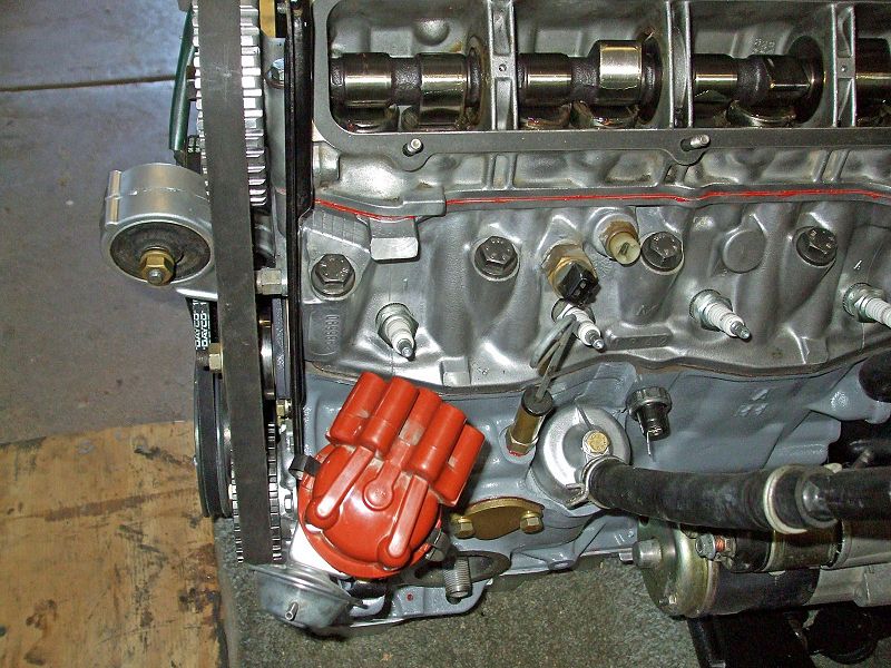
With the belt cover removed, the cam pulley, belt tensioner pulley, and auxiliary shaft pulley are all visible.
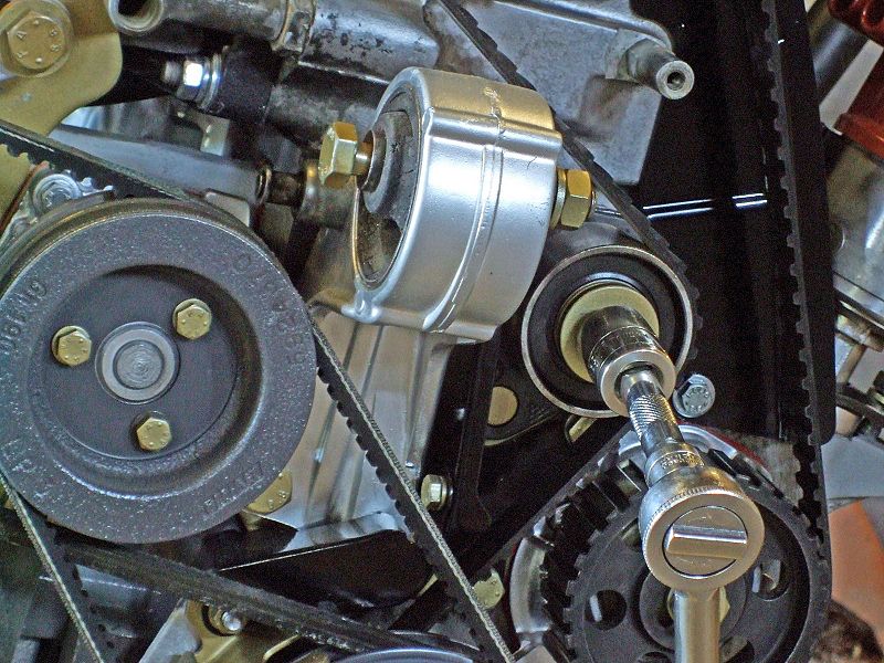
Photo 4
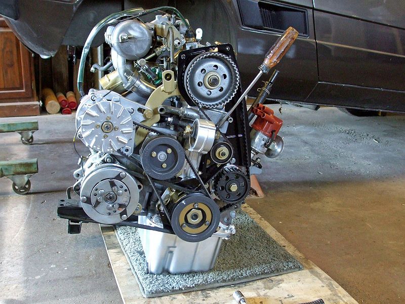
Using a 17mm socket, loosen the tensioner pulley nut. The tensioner pulley is situated on bracket secured by a large gold pin to the lower left of the pulley. This allows the pulley to be rotated to the left while remaining on its attaching stud. You will not have to remove this pulley to remove or change the belt - just move it to the side.
Photo 5
You can use a large slotted screwdriver to press against the tensioner pulley bracket, using the belt cover stand off as a fulcrum.
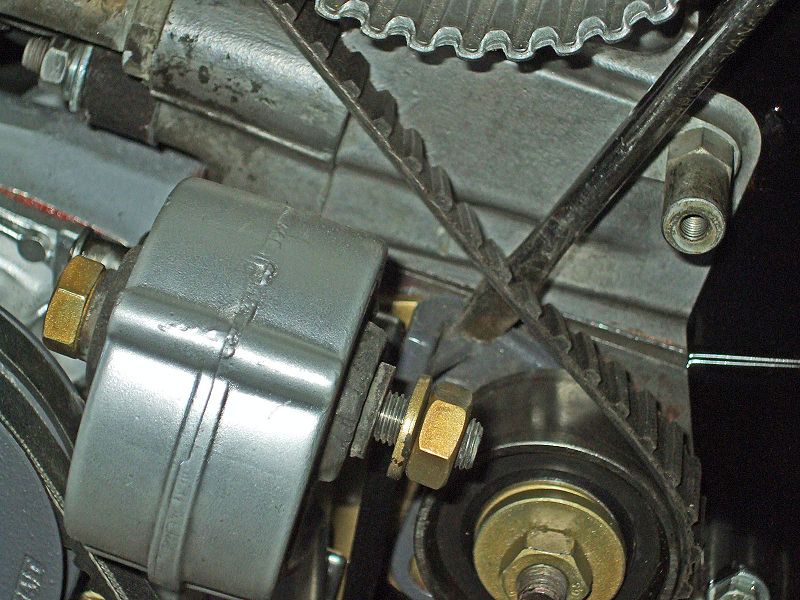
Photo 6
This shows the flange at the base of the tensioner pulley bracket. You need to move the tensioner pulley to the left (towards the rear of the engine) to release the tension on the timing belt.
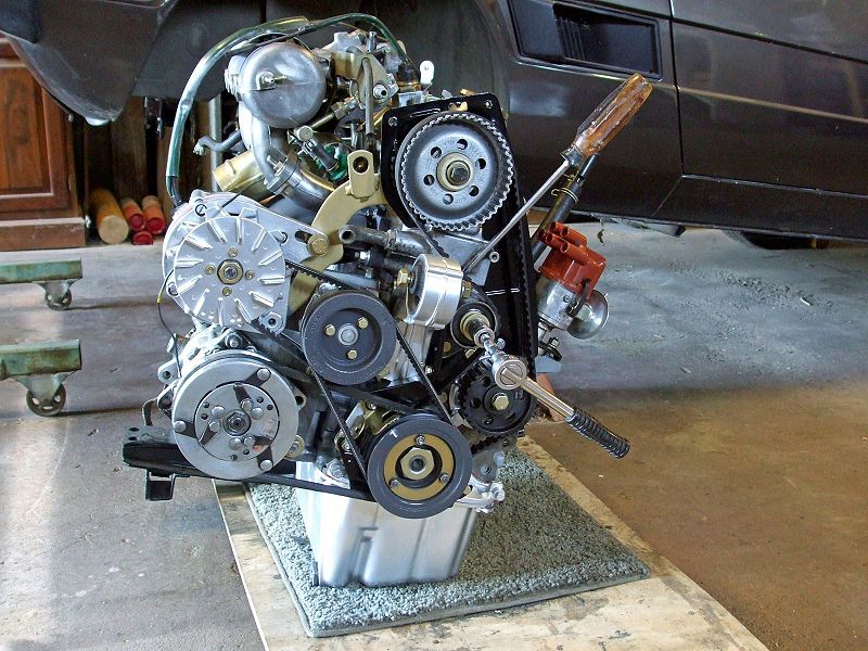
Photo 7
With the tension on the belt released, tighten the tensioner pulley nut to keep the pulley in place while removing the timing belt.
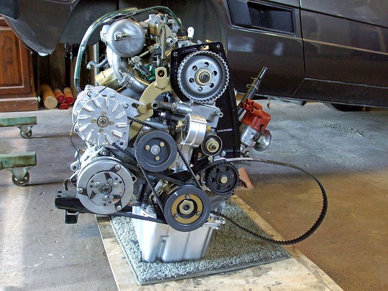
Photo 8
The timing belt can now be pulled off the cam pulley.
Photo 9
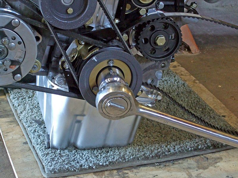
Use a 38mm socket to loosen the crankshaft nut. The timing belt is situated behind the crank pulley on the timing belt sprocket.
Photo 10
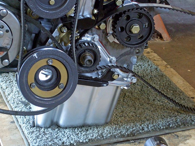
The crankshaft pulley has been slipped off the crankshaft, exposing the timing belt sprocket. The crank pulley is left hanging on the belts for the water pump, a/c compressor, and alternator.
Photo 11
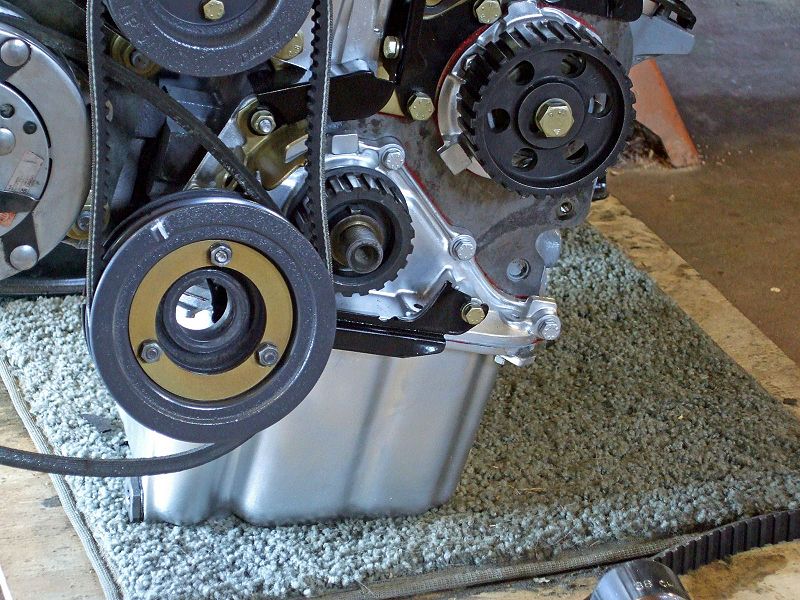
Remove the timing belt and discard.
Photo 12
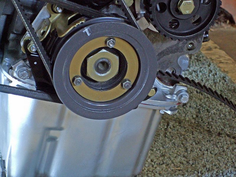
Fit a new timing belt to the sprocket, replace the crank pulley and tighten the crank pulley nut. Ensure that the crank pulley is still at TDC.
Photo 13
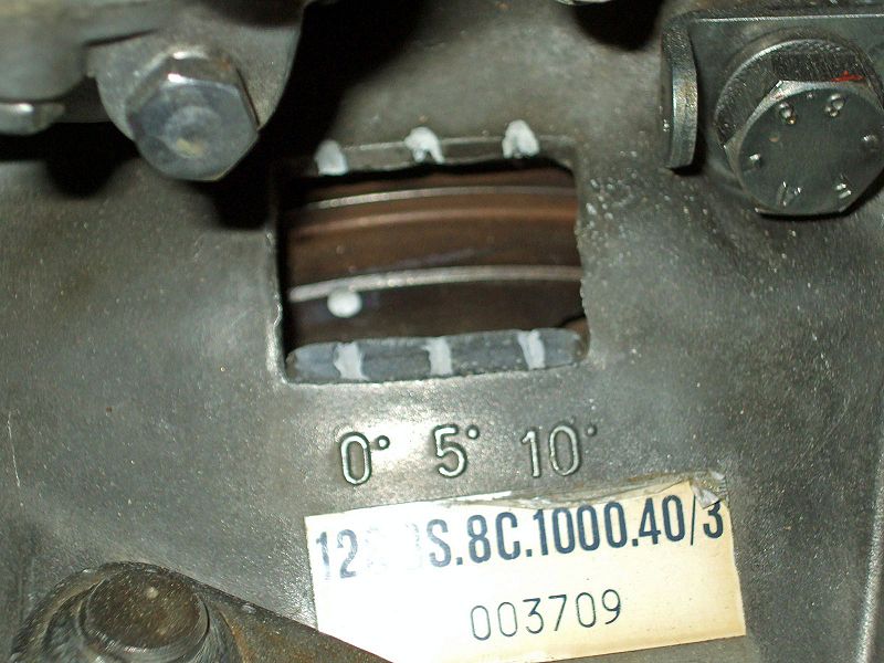
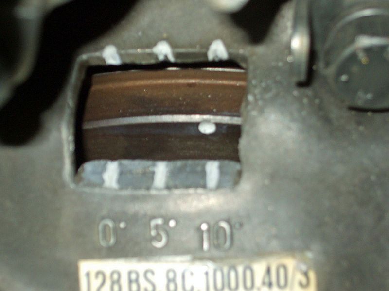
If the crank pulley is at TDC, the dimple on the flywheel (seen through the opening in the transmission bell housing on the clutch side of the engine) should be in alignment with the 0º mark on the transmission housing. Note: If your flywheel has not been installed correctly, you will not be able to see the dimple. Also, the dimple and marks shown here have been painted for contrast.
Photo 14
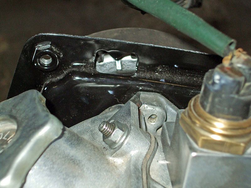
Ensure the cam pulley is aligned with the pointer on the belt guard. Note: For a 1300cc engine, the cam pulley should align with the pointer on the side engine mount.
Photo 15
With the cam and crank pulleys aligned with their TDC marks, slip the belt back into position around all pulleys (crank, auxiliary, tensioner and cam). Loosen the nut on the tensioner pulley to allow the pulley put tension on the belt. You may need to assist the pulley return to a normal position but do not unduly force it or you may over-stress the belt. Retighten the tensioner pulley nut.
Photo 16
Use the 38mm socket to rotate the crankshaft completely around two times. Repeat the tensioner pulley loosening and tightening procedure. Rotate the engine twice more stopping with the crank pulley at the TDC mark. Ensure the cam pulley is still aligned with its pointer. If all is in alignment, the cam timing is correct and the timing belt has been correctly replaced. Lastly, replace the yellow timing belt cover.
Setting the Static Ignition Timing
First, it is advisable to ensure that the timing of the crankshaft and cam pulleys line up with their respective TDC marks as shown in photos 12, 13 & 14 above. If these are correct, go through the following photos to set the static ignition timing.
Photo 17
Use a 38mm socket to rotate the crankshaft clockwise until the mark on the crank pulley is aligned with the 10º BTDC pointer on the timing finger. Note: This photo shows the crank stopped at 10º BTDC, which is the static ignition timing required for a fuel injected engine. For a carbureted engine, the crank should be set to 5º BTDC.
Photo 18
If the crankshaft has been rotated correctly and stopped on the 10º BTDC mark, the dimple on the flywheel will also be aligned with the 10º mark on the transmission housing.
Photo 19
With the crankshaft pulley set to 10º BTDC, remove the distributor cap to expose the distributor's rotor. The distributor needs to be positioned so that the rotor points to the contact for #4 cylinder spark plug lead in the distributor cap
Photo 20
To set the required distributor position, undo the 13mm nut at the base of the distributor and remove the nut, washer and locking bracket.
Photo 21
Remove the distributor from the engine and turn the rotor until it points toward the #4 cylinder contact in the distributor cap. Refit the distributor and locking bracket and secure with the 13mm washer and nut. Replace the distributor cap.
Note: It is easier if the fingers of the distributor cap point towards #3 cylinder as this makes the placement of the spark plugs leads neater and should leave sufficient room to rotate the distributor body when dynamically setting the ignition timing.
That’s it, you’re done.
With everything else being correct, the engine should now start and you can then use a timing light to set the ignition timing exactly.
Dan's write up; There are two types of timing: Cam/valve/engine and ignition.
People variously use the terms cam, valve, and engine timing to describe the same concept, which appropriately enough is getting the moving parts of the engine (cam, valves, distributor and engine crankshaft and therefore pistons) to all sync up the way they need to.
On an X1/9, getting the above synched up involves positioning the cam and crank timing marks, BUT, when they are positioned properly, cyl #4 and NOT cyl #1 happens to be on the compression stroke.
But, when you get the cam and crank timing set, because the dist is run from the aux shaft whose drive sprocket has no specific positional relationship to the cam and crank sprockets, the distributor is synced to the cam and crank in a separate step on an X1/9.
One more thing about that....when the cam and crank timing marks are set, that does not necessarily mean that the timing pointers on the pulley end of the engine are perfectly set. The are sheet metal, and the holes by which the pointers are mounted to studs are bigger than the studs, and therefore can be off as much as 5-10 degrees. The most accurate pointers are the hash marks on the bell housing that line up with the dot/dimple on the flywheel. These are visible thru the "window" at the 12 o'clock position on the bell housing.
The other type of timing, ignition, on an X1/9 is just like on most other cars, getting the spark delivered to the cylinder at the right time as shown to you by a timing light. While on the X (and most 4 cylinder engines) you can set ignition timing from the #1 or #4 cylinder, 99.9% of the time people will set ignition timing with the timing light connected to #1 cyl.
Follow these steps (apply only to 1500 engines):
1. Park on a hard level surface, parking brake off, chock a wheel for safety. Trans in 4th gear.
2. Using a floor jack positioned under the right rear suspension, raise the right rear wheel just enough to clear the ground/floor
4. Remove spare tire and distributor access panel.
5. Remove the black plastic cap from the timing window at the top of the trans bell housing and from the top of the yellow plastic cam belt cover
6. Grasp the right rear tire (or put a lug wrench on a lug nut) and slowly turn the wheel clockwise until you see the timing notch/dimple on the cam sprocket line up with the pointer. When these are lined up, you are at TDC of Cyl #4 on the compression stroke. Yes, this is what you want for the moment.
- WARNING! DO NOT rotate the wheel counterclockwise for ANY reason....this would rotate the engine backwards, possibly causing the timing belt to jump teeth. If you over-rotate the wheel and miss a mark, no problem, just keep turning and get it on the next go-around.*****
7. Now, go around the other side and check the hash marks on the bell housing and the dot on the flywheel. The dot should be lined up with the Zero hash mark.
NOTE: If the dot does not line up with the Zero has mark, recheck your work. If you are sure the cam hash mark or dot is lined up with the cam cover backing plate pointer, there are explanations: the flywheel may have been install 180 degrees out; the cam belt may have jumped teeth, or the cam sprocket has some sore of mounting issue.
8. Take this opportunity to highlight the hash marks, dots, pointers and such with white or yellow paint and a fine brush. Don't bother with the pointers at the pulley end of the engine, they are IMHO pretty much useless (too hard to see at a direct angle when using a timing light and too hard to get to, to adjust). If you insist upon using the pulley end pointers, now is the time to make sure they are adjusted accurately and marked with paint.
9. To recap, cam sprocket notch/dimple lined up with cam cover backing plate pointer = #4 TDC on compression stroke. Verify with dot and hash mark on trans bell housing. If all good, reach into the car and apply the handbrake, locking it down.
Assuming all of the above is good, proceed to syncing the distributor.
10. The position of the dist body on its engine block mounting pad is not located critically like the cam and crank are, and that explains why there are no hash marks on the dist or the mounting pad to line up. Practically speaking, the best position for the distributor body is with the vac capsule on the right (pass) side of the car, and assuming you have the dist cap with the side-loading wires, the wire terminals pointing to the left rear shock tower. This allows the stock length wires to fit nicely and allows enough room for the vac capsule to swing without hitting anything (like the side of the cam belt cover and backing plate) as you rotate the distributor to adjust ignition timing.
11. If your dist is not positioned as above, remove the 13mm hold down nut and hold down, raise the dist body away from its engine mounting pad by about 2", rotate the dist body as needed, then lower it back down. The inside end of the dist shaft is splined to the aux shaft, so you may have to rotate the dist a little bit one way or the other to get it to sit back down into its position. Again, the position of the dist body is not critical so don't sweat it....just get the vac capsule on the right and have the spark plug wire terminals point to the left rear shock tower. Don't reinstall the holddown just yet.
12. Next, pop the cap off of the distributor body, flip it over, and examine its condition. The center button and the four metal contacts should be in good condition. The take a look at the rotor, make sure its center contact pad (that mates with the button on the cap) and the rotor tip are also in good condition.
13. Looking at the design of the cap, trace the path of the #4 spark plug wire from its terminal on the exterior of the cap and find its internal contact along the inside top of the cap. Using a Sharpie marker or equivalent, place a vertical hash mark directly below this contact along the bottom edge of the cap, both inside and outside. Replace the cap onto the dist, making sure to line up the notch in the dist body rim with the corresponding bump along the bottom edge of the cap. Hold the cap in place securely, and then make a vertical mark on the exterior of the dist body just below the cap. Don't worry if you happen to jostle the dist body out of place a little while doing this; just so you get it back to where you had it in step 11.
14. Now remove the cap from the dist body and set aside. What we want to see is the center of the tip of the rotor pointing directly at the vertical hashmark you made on the dist body. If it is, great, go on to the next step. If not, pull the dist body out of the block by about 2", hold with one hand, trying not to rotate the dist left or right, then with the other hand, rotate the rotor so that the center of the rotor's tip is pointing to your hashmark on the dist body, then with both hands maintain their positions, lower the dist body back into the block. If you accidentally rotated the dist body too much, pull it out of the block by about 2", reposition, and try again. If the dist body positioning is still good but when you lower the dist back into the block the rotor wants to rotate away from the hashmark, that's normal. As long as the hashmark lines up within the arc of the rotor tip contact, you are close enough to proceed to the next step.
15. Without rotating the dist body, install the dist holddown , washers and nut, and tighten snugly but not completely. Replace the cap and clip the cap into place.
16. Recheck that parking brake is applied, lower the right rear wheel from the jack, place trans in neutral.
17. Now you are ready to check ignition timing with a timing light. Install the light according to manufacturer's instructions; if the timing light has a knob to adjust the light to the advance, make sure for now it is set to Zero. Technically you can set ignition timing from either the #1 or the #4 cylinder ignition wire/spark plug, but most people will use #1.
18. Follow the factory shop manual instructions on preparing the car for checking and setting ignition timing. For example, on a fuel injected car, you should ensure that the car is warmed up, that the idle speed is around 900 RPM, and that the vac line to the vac advance capsule is removed from the vac advance capsule and plugged at the vac advance capsule end. Carb people should follow the carbed car procedure. Make a note of what your idle speed is before continuing.
NOTE: For the following adjustment steps, a helper to turn the dist body saves a lot of hassle.
19. From as direct an angle as possible given the confined area in which we have to work, point the timing light at the timing marks visible in the bell housing window (or the pointers on the pulley end of the engine). If you cannot see the dot on the flywheel or the hashmark on the crank pulley, then your setup is either way too advanced or way too retarded. Go around to the dist access panel, loosen the 13mm holddown nut, rotate the dist body about 1/2" in either direction, snug the nut, and have another look with the timing light. If you can now see the dot or hashmark, good. If not, back to the dist, loosen the nut, and this time rotate an inch in the opposite direction, tighten and check the light. If you still cannot see the dot/hashmark, repeat the adjusting process a 1/2" at a time until the timing marks come into view.
NOTE: If you can see your timing marks but they seem to be "jumping" all over the place, try a different timing light. There will be some small degree of dot/hashmark movement visible under the light, but too much movement will prevent you from accurately adjusting timing. If you have tried several good-quality lights and still see excessive movement, then that could be an indicator of mechanical issues in the distributor, a loose cam belt, or problems within the ignition system.
20. Once you have them in view, continue the process of rotating the dist body and checking the marks. The ignition timing spec is 10 degrees before for FI cars and IIRC, 5 degrees before for carbby cars. Once set to spec, don't forget to securely tighten the holddown nut.
21. Be sure to replace any disconnected vacuum lines!
22. If your ignition timing was way off, it could have affected your idle speed and/or idle quality....if it has changed significantly from what it was in step 18 before you started, follow the factory shop manual procedure to adjust.
23. Before buttoning up the dist access panel and replacing the spare, take it for a test drive and observe for unusual sounds or behavior. Hopefully it runs better than ever!
