Tuning
While there are a few ways to tune the Marelli 8GMx on your own, by far the easiest is by using an OpenFlash Tablet, along with the provided definition/index files listed below. Feel free to contact me (Jonohhh on the Forums) if you are having issues finding a definition, and I will try to help as I can.
The following is courtesy of Brodey Dover, who has kindly written this article as a thread on Fiat500USA. I have consolidated it here so it can remain preserved should anything happen to the Forum, and to help spread this information to our community.
Index Repository Here: Index Files
You can try to find the XDF file for your calibration, however, if you have an index file that isn't in the repository please contact me and I'll upload it to share for the community.
Download Tuner Pro RT: http://tunerpro.net/downloadApp.htm
Introduction To The Tables
Turbo Pressure 1: This is the non-sport boost targets in mbar. Make sure to subtract ambient pressure to arrive at the target. Also note, that altitude will affect the resultant boost targets.
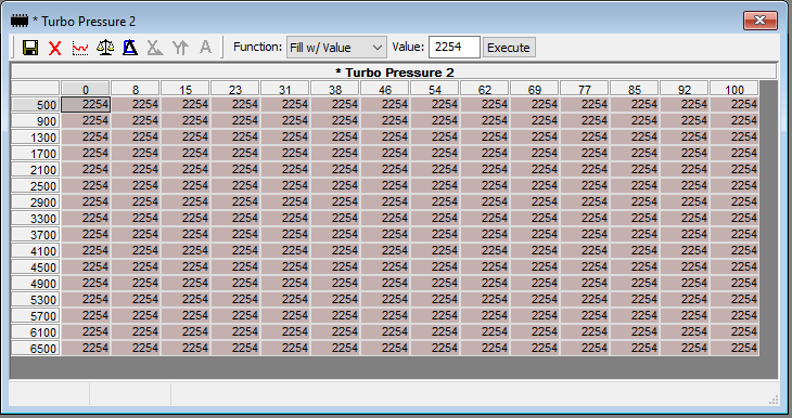
Turbo Pressure 2: This is the sport mode boost targets in mbar.
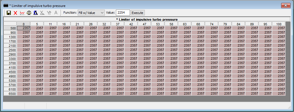
Limiter of impulsive turbo pressure: This is your boost cut table. You can use this table like a typical boost cut table with a fixed value; don't worry though your torque targets will limit total boost anyway.
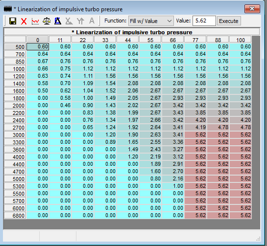
Linearization of impulsive turbo pressure: This table acts like WGDC, but the values are in "Frequency". If your turbo isn't hitting your targets you can try to increase the values here to see if that improves things. I use a max of 5.6Hz.
Torque request during take off condition/standard condition #1/#2 and Torque Request: These are the computed values that the ECU will try to achieve. The calculations are not trivial and not obvious so without full access to the other torque tables, it is wise to leave these alone...for now.
Optimal Engine Torque (#1/#2): This is actually an airflow table, we will crank this up to allow for maximum airflow.
Ignition Advance (1/2/3/4/5): This is your timing Advance maps. In "good" conditions, these tables will be used to add timing on top of the base maps.
Spark Advance base map (1,2,3,4): These are the ignition timing maps.
Optimal spark base map (1,2): This table doesn't appear to be defined correctly. I've never touched it.
Injection Base map (1,2): Same deal, never touched it, never needed to.
Requested AFR: This is your base fuel map.
Requested AFR Beta: Don't touch this, it isn't defined correctly.
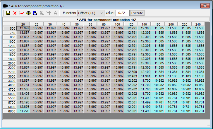
AFR for component protection (1,2): This are your "oh ****" fuel maps. If there is some knock, increased thermals, etc. the ECU will start to engage #1. If however...things get messy and pass the max thresholds, #2 will kick in and the fuelling will increase dramatically. You can see this behaviour on the stock tune where the ECU will command AFRs in the 10s around 4500RPM. The base fuel map only commands this AFR at 6000RPM and above.
Rev Limiter: This is indeed your rev limiter. Just note though, that we can't resize indexes so we have to balance what the car wants at 6600RPM and what the car wants at your raised rev limiter.
Speed limiter: This is indeed your speed limiter.
Introduction To Tuning
I'll create base maps for each calibration but for now I'll go through some of the "thinking" behind the base map tuning so you can take it and make it your own. I strongly suggest perfecting the ability for you to log spark knock reduction, Throttle Position %, Engine RPM and Engine Speed. There are other key items that you can use later, but for those 7 inputs you'll monitor engine combustion health as well as being able to import your logs into virtual dyno for comparison. My suggestion is to find a flat road and use markings to ensure that you are starting the log at the same place every time you do a 2nd gear or 3rd gear pull. I don't recommend 4th gear pulls unless you have a good lawyer and you are 100% certain any members of the public will not be affected. Keep your EYES on the road.
Fuel Tables: Looking at the base fuel map (Requested AFR), we see that the 20kPa load cell column starts at 14.7 but works its way to 11.929. This column is a specially defined column used when calibration the TLC knock prediction adaptive. Long story short, FCA expects a certain performance of knock that will characterize the engine and its fuel within the context of certain parameters; mostly for the purpose of predicting partial throttle areas so leave this one column alone. Play with it at your own risk, if you must. Moving on we see a similar case for the high load columns and here is where we'll spend most of our work. I'll go ahead and select columns 23-140 and set all cells to 14.7 to target stoich. I'll set columns 180-240 to 12.5. I use NA power targets until boost can ramp in reliably so I'll start adding some more fuel progressively from 2700 onward. Peak torque lines up with peak cylinder pressure so we want to be running at our ideal/safe AFR during peak torque/peak boost. Finally, we need to balance the air and fuel carefully at the top because the cylinders don't like having too much fuel so don't be overzealous (like OEM) but don't push timing/boost near redline either. In this case, I used 11.7 as a target which is a common starting off point for forced induction vehicles. We'll want to blend our Power AFR targets with our stoich target cells so we'll divide the difference by 4 and blend by adding the 1/4 difference to the next two cells.
That should leave us with this:

We aren't done just yet though. In my experience, the power of the car is noticeably reduced when any of the fuel "correction" tables are leveraged in any manner. If your coolant temp is approaching 100C, IATs are approaching 50C+, Cat Temps are approaching 800C or if there is a pattern of knock that doesn't relate to tip-in or transients. The computer will start adding fuel to keep things "cool" and reduce the conditions that create knock. To my point, power is reduced any time any of these tables are used so let's make them the same so we can easily identify what is going on while we're out logging. Then we can consider higher octane fuels, reducing IATs or letting the car cool off/take some time off of tuning and power pulls. The two tables that are relevant here will be AFR for component protection (1 and 2) as well as Lambda for component protection 2. Let's select all cells from the Requested AFR table and copy the values. Next, we'll paste the cells into each of the three compensation tables. Right off the bat, I'll subtract 0.7 AFR points so that we're idling at 14.0 We'll notice now that we're at 11.0 at high RPM and high engine load, so let's pull another 0.3 points of fuel but only from cells 180-240. Excellent, when the car wants to cool things off we'll be running cooler than OEM in our street driving cells but we're not overfuelled either. When we hit high load, we'll start off at 11.5 so the car may be a bit sluggish here and as we pull, we'll max out at 10.78 which is max. richness for most FI targets. You can pull fuel if you find the car loaded up on fuel in typical driving like stop and go during the summer, but be cautious about reducing fuel above 2700RPM since that is when the turbo will begin to light up. We can now select all cells from our AFR for component protection 1/2 table and paste the values into AFR for component protection 2/2 and Lambda for component protection 2 tables.
Here is what I have for my compensation tables:
Turbo Tables: For turbo related tuning we have four tables: Turbo Pressure (1, 2), Limiter of impulsive turbo pressure and Linearization of impulsive turbo pressure. The Turbo pressure tables will define the boost pressure targets in mbar, note, you have to remove atmosphere pressure to reach your final pressure. 1 atm = 14.7 psi = 1013mbar. So let's say we want the stock peak pressure of 18psi: 18 psi = 1241 mbar, then add atmosphere 1013 mbar and we get = 2254 mbar. Now looking at the OEM table we see values in and around that 18psi range, but we will also need to consider the boost cut which we'll dive into some more. With closed loop boost control, you can real contour how the torque will be created with the engine, but we'll set things up so it's going to behave more around a mechanical boost setup. I'll select all cells in Turbo Pressure 2 (sport mode boost) and paste in our 2254mbar value. For non-sport, we can target 12psi so again, we convert 12 psi to mbar-> 827 mbar and we add in atmosphere of 1013 mbar for a total = 1840 mbar. We'll do the same as in Turbo Pressure 2 but for Turbo Pressure 1 (Non sport mode boost).
Here is the target Boost Table:
This one is important, we'll want to ensure that we don't overshoot boost too much so we'll want to cap things off. You can play with the cut values to see how harsh/smooth the ECU reacts to overboosting but I'll start by placing the cut 1.5psi above our target so it is a decent middle ground. So we'll continue as above and fill in the table with 2357mbar for 19.5psi and paste that into Limiter of impulsive turbo pressure. Filling in the table with the same value will emulate a mechanical boost cut but you can spend some time experimenting with torque limits at lower throttle/load areas.
Boost Cut Table:
The final turbo related table is the Linearization of impulsive turbo pressure. Again, this is in Hz so we're dependent on hardware limitations on speed and precision. Just because we command 3.0Hz doesn't mean we'll get it from the hardware. One way to get reliable boost targets is to populate the cells from 77 to 100 with high values like 5.62 from 3000RPM and above.
Something like this:
ProTips For Tuning Specific Tables
TBD
Base Map Repository Here: <TBD>
Get Your Fresh Base Maps Here!